D-Link DES-1210-08P Reference Manual
Des-1210 series web smart switch
Hide thumbs
Also See for DES-1210-08P:
- Specifications (4 pages) ,
- User manual (8 pages) ,
- Manual (15 pages)
Table of Contents
Advertisement
Quick Links
Advertisement
Table of Contents

Related Manuals for D-Link DES-1210-08P


Summary of Contents for D-Link DES-1210-08P
-
Page 2: Table Of Contents
Connecting to the Switch .......................... 12 Login Web-based Management ....................... 12 Smart Wizard ............................... 13 Web-based Management ..........................13 D-Link Network Assistant (DNA) ........................13 Configuration.............................. 15 Smart Wizard Configuration ......................... 15 IP Information ............................15 Password Settings ............................ 15 SNMP Settings ............................ - Page 3 System > Time Profile ..........................30 System > Power Saving ........................... 31 System > IEEE802.3az EEE Settings ...................... 31 System > D-Link Discover Protocol Settings .................... 32 VLAN > 802.1Q VLAN (Asymmetric VLAN) ..................... 33 VLAN > 802.1Q VLAN PVID ........................34 VLAN >...
- Page 4 ACL > ACL Access Group ........................74 ACL > ACL Hardware Resource Status ....................75 PoE > PoE Global Settings (DES-1210-08P/28P only) ................75 PoE > PoE Port Settings (DES-1210-08P/28P only) ................75 SNMP > SNMP > SNMP Global Settings ....................77 SNMP >...
- Page 5 Table of Contents DES-1210 Series Switch Web UI Reference Guide CLI Commands: ............................85 download ..............................85 upload ............................... 86 config ipif system ............................86 logout ................................ 87 ping ................................87 reboot ............................... 87 reset ................................88 show ipif ..............................88 show switch ..............................
-
Page 6: About This Guide
Reproduction in any manner whatsoever without the written permission of D-Link Corporation is strictly forbidden. Trademarks used in this text: D-Link and the D-LINK logo are trademarks of D-Link Corporation; Microsoft and Windows are registered trademarks of Microsoft Corporation. Other trademarks and trade names may be used in this document to refer to either the entities claiming the marks and names or their products. -
Page 7: Product Introduction
The intuitive SmartConsole easily allows customers to discover multiple D-Link web smart switches in the same L2 network segment. With this utility, users do not need to change the IP address of PC and provides easy initial setting of smart switches. -
Page 8: Des-1210-08P
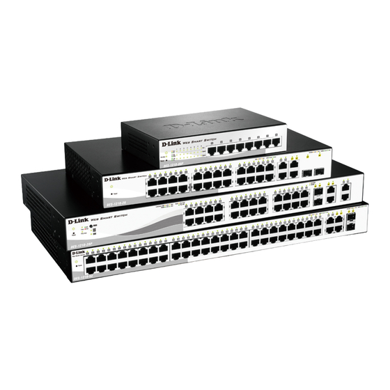
8-Port 10/100Mbps ports Web Smart PoE Switch. Front Panel Figure 1.1 – DES-1210-08P Front Panel Power LED : The Power LED lights up when the Switch is connected to a power source. Pwr Max: The Pwr Max LED lights up when the Switch reaches the maximum power budget defined by the administrator via PoE System Settings page of Web GUI or the default power budget of 72 Watts. -
Page 9: Rear Panel
1 Product Introduction DES-1210 Series Switch Web UI Reference Guide Port Link/Act/Speed LED (1-24): The Link/Act/Speed LED flashes which indicates a network link through the corresponding port. Blinking indicates that the Switch is either sending or receiving data to the port. When a port has amber light indicates that port is running on 10M. -
Page 10: Rear Panel
1 Product Introduction DES-1210 Series Switch Web UI Reference Guide data to the port. When a port has amber light indicates that port is running on 10M or 100M. When it has a green light it is running on 1000M. NOTE: On DES-1210-28P, the MiniGBIC ports are shared with normal RJ-45 ports 27 and 28. -
Page 11: Rear Panel
1 Product Introduction DES-1210 Series Switch Web UI Reference Guide Class I. 3.3Vdc. Rear Panel Figure 1.4 – DES-1210-52 Rear Panel Power: Connect the supplied AC power cable to this port. -
Page 12: Hardware Installation
DES-1210 Series Switch Web UI Reference Guide Hardware Installation This chapter provides unpacking and installation information for the D-Link Web-Smart Switch. Step 1: Unpacking Open the shipping carton and carefully unpack its contents. Please consult the packing list located in the User Manual to make sure all items are present and undamaged. -
Page 13: Step 3 - Plugging In The Ac Power Cord With Power Cord Clip
2 Hardware Installation DES-1210 Series Switch Web UI Reference Guide Then, use the screws provided with the equipment rack to mount the switch in the rack. Figure 2.3 – Mount the Switch in the rack or chassis Please be aware of following safety Instructions when installing: A) Elevated Operating Ambient - If installed in a closed or multi-unit rack assembly, the operating ambient temperature of the rack environment may be greater than room ambient. - Page 14 2 Hardware Installation DES-1210 Series Switch Web UI Reference Guide Figure2.1 – Insert Tie Wrap to the Switch B) Plug the AC power cord into the power socket of the Switch. Figure 2.2 – Connect the power cord to the Switch C) Slide the Retainer through the Tie Wrap until the end of the cord.
- Page 15 2 Hardware Installation DES-1210 Series Switch Web UI Reference Guide D) Circle the tie of the Retainer around the power cord and into the locker of the Retainer. Figure 2.4 – Circle around the power cord E) Fasten the tie of the Retainer until the power cord is secured. Figure 2.5 –...
-
Page 16: Power Failure
2 Hardware Installation DES-1210 Series Switch Web UI Reference Guide Figure 2.6 – Plugging the switch into an outlet Power Failure As a precaution, the switch should be unplugged in case of power failure. When power is resumed, plug the switch back in. -
Page 17: Getting Started
This chapter introduces the management interface of D-Link Web-Smart Switch. Management Options The D-Link Web Smart Switch can be managed through any port on the device by using the Web-based Management or through any PC using the SmartConsole Utility. Each switch must be assigned its own IP Address, which is used for communication with Web-Based Management or a SNMP network manager. -
Page 18: Smart Wizard
English. Figure 3.3 – Logon Dialog Box Smart Wizard After a successful login, the Smart Wizard will guide you through essential settings of the D-Link Web Smart Switch. Please refer to Smart Wizard Configuration section for details. Web-based Management By clicking the Exit button in Smart Wizard, you will enter the Web-based Management interface. - Page 19 3 Getting Started DES-1210 Series Switch Web UI Reference Guide For detailed explanations of the DNA functions, please refer to D-Link Network Assistant (DNA) User Guide..
-
Page 20: Configuration
4 Configuration DES-1210 Series Switch Web UI Reference Guide Configuration The features and functions of the D-Link Web Smart Switch can be configured for optimum use through the Web-based Management Utility. Smart Wizard Configuration After a successful login, the Smart Wizard will guide you through essential settings of the D-Link Web Smart Switch. -
Page 21: Snmp Settings
4 Configuration DES-1210 Series Switch Web UI Reference Guide Figure 4.2 – Password setting in Smart Wizard SNMP Settings The SNMP Setting allows you to quickly enable/disable the SNMP function. The default SNMP Setting is Disabled. Click Enabled and then click Apply to make it effective. 4.3 –... -
Page 22: Web-Based Management
Logout button first, then it will be seen as an abnormal exit and the login session will still be occupied. Finally, by clicking on the D-Link logo at the upper-left corner of the screen you will be redirected to the local D-Link website. -
Page 23: Tool Bar > Save Menu
4 Configuration DES-1210 Series Switch Web UI Reference Guide Tool Bar > Save Menu The Save Menu provides Save Configuration and Save Log functions. Figure 4.6 – Save Menu Save Configuration Select to save the entire configuration changes you have made to the device to switch’s non-volatile RAM. Figure 4.7 –... -
Page 24: Reboot Device
4 Configuration DES-1210 Series Switch Web UI Reference Guide Reboot Device Provide a safe way to reboot the system. Click Apply to restart the switch. Figure 4.12 – Tool Menu > Reboot Device Configuration Backup & Restore Allow the current configuration settings to be saved to a file (not including the password), and if necessary, you can restore configuration settings from the file. -
Page 25: Tool Bar > Smart Wizard
Tool Bar > Online Help The Online Help provides two ways of online support: Online Support Site will lead you to the D-Link website where you can find online resources such as updated firmware images; User Guide can offer an immediate reference for the feature definition or configuration guide. -
Page 26: Function Tree
4 Configuration DES-1210 Series Switch Web UI Reference Guide Figure 4.16 – User Guide Micro Site Function Tree All configuration options on the switch are accessed through the Setup menu on the left side of the screen. Click on the setup item that you want to configure. The following sections provide more detailed description of each feature and function. -
Page 27: Device Information
4 Configuration DES-1210 Series Switch Web UI Reference Guide Figure 4.17 –Function Tree Device Information The Device Information provides an overview of the switch, includes essential information such as firmware & hardware information, and IP address. It also offers an overall status of common software features: RSTP: Click Setting to link to L2 Functions >... -
Page 28: System > System Settings
4 Configuration DES-1210 Series Switch Web UI Reference Guide System > System Settings The System Setting allows the user to configure the IP address and the basic system information of the Switch. IP Information: There are three ways for the switch to obtain an IP address: Static, DHCP (Dynamic Host Configuration Protocol) and BOOTP. -
Page 29: System > Ipv6 Route Settings
4 Configuration DES-1210 Series Switch Web UI Reference Guide DHCPv6 Client: Specifies the DHCPv6 client to be enabled or disabled. IPv6 Network Address: Specifies the IPv6 Network Address. NS Retransmit Time Settings: NS Retransmit Time (1-3600): Specifies the NS retransmit time for IPv6. The field range is 1-3600, and default is 1 second. -
Page 30: System > Password
4 Configuration DES-1210 Series Switch Web UI Reference Guide Interface Name: Specifies the interface name of the IPv6 neighbor. To search for all the current interfaces on the Switch, go to the second Interface Name field in the middle part of the window, tick the All check box. Tick the Hardware option to display all the neighbor cache entries which were written into the hardware table. -
Page 31: System > Port Description
4 Configuration DES-1210 Series Switch Web UI Reference Guide Speed: Gigabit Fiber connections can operate in 1000M Full Force Mode, Auto Mode or Disabled. Copper connections can operate in Forced Mode settings (1000M Full, 100M Full, 100M Half, 10M Full, 10M Half), Auto, or Disabled. -
Page 32: System > Dhcp Auto Configuration
4 Configuration DES-1210 Series Switch Web UI Reference Guide System > DHCP Auto Configuration This page allows you to enable the DHCP Auto Configuration feature on the Switch. When enabled, the Switch becomes a DHCP client and gets the configuration file from a TFTP server automatically on next boot up. -
Page 33: System > Dhcp Relay > Dhcp Relay Interface Settings
4 Configuration DES-1210 Series Switch Web UI Reference Guide DHCP Relay Agent Information Option 82 Check: This field can be toggled between Enabled and Disabled using the pull-down menu. It is used to enable or disable the Switches ability to check the validity of the packet’s option 82. -
Page 34: System > Dhcp Local Relay Settings
4 Configuration DES-1210 Series Switch Web UI Reference Guide System > DHCP Local Relay Settings The DHCP Local Relay Settings page allows the user to configure DHCP Local Relay. DHCP broadcasts are trapped by the switch CPU, and replacement broadcasts are forwarded with Option 82. Replies from the DHCP servers are trapped by the switch CPU, the Option 82 is removed and the reply is sent to the DHCP Client. -
Page 35: System > Syslog Host
4 Configuration DES-1210 Series Switch Web UI Reference Guide System > SysLog Host System Logs record and manage events, as well as report errors and informational messages. Message severity determines a set of event message will be sent. Click Enable so you can start to configure the related settings of remote system log server, then press Apply for the changes to take effect. -
Page 36: System > Power Saving
4 Configuration DES-1210 Series Switch Web UI Reference Guide System > Power Saving The Power Saving mode feature reduces power consumption automatically when the RJ-45 port is link down or the connected devices are turned off. Less power will be consumed also when the short cable is used (less than 20 meters). -
Page 37: System > D-Link Discover Protocol Settings
Disable EEE function on the switch port. System > D-Link Discover Protocol Settings For the D-Link Discovery Protocol (DDP) supported device, this page is an option for you to disable DDP or configure the DDP packet report timer. Figure 4.35 – System > D-Link Discover Protocol Settings D-Link Discover Protocol State: Enable or disable the Discover Protocol state. -
Page 38: Vlan > 802.1Q Vlan (Asymmetric Vlan)
4 Configuration DES-1210 Series Switch Web UI Reference Guide VLAN > 802.1Q VLAN (Asymmetric VLAN) This function is located in the 802.1Q Configuration page. It allows devices in different VLANs to communicate with the servers, firewalls or other shared resources in the shared VLAN. This configuration is accomplished in three steps: Enabling Asymmetric VLAN function Creating shared VLAN and access VLAN... -
Page 39: Vlan > 802.1Q Vlan Pvid
4 Configuration DES-1210 Series Switch Web UI Reference Guide The VLAN settings of this example are: VLAN 1: default VLAN 1, including all ports with untagged. VLAN 2: Member ports are untagged port 5, 15-18, 20. VLAN 3: Member ports are untagged port 6, 15-18, 20. VLAN 4: Member ports are untagged port 7, 15-18, 20. - Page 40 4 Configuration DES-1210 Series Switch Web UI Reference Guide Figure 4.41 – VLAN > Voice VLAN > Voice VLAN Global Setting Voice VLAN State: Select to enable or disable Voice VLAN. The default is Disabled. After you enabled Voice VLAN, you can configure the Voice VLAN Global Settings. VLAN ID: The ID of VLAN that you want to assign voice traffic to.
-
Page 41: Vlan > Voice Vlan > Voice Vlan Port Setting
Similar as Voice VLAN, Auto Surveillance VLAN is a feature that allows you to automatically place the video traffic from D-Link IP cameras to an assigned VLAN to enhance the IP surveillance service. With a higher priority and individual VLAN, the quality and the security of surveillance traffic are guaranteed. The Auto Surveillance VLAN function will check the source MAC address / VLAN ID on the incoming packets. -
Page 42: L2 Functions > Jumbo Frame
L2 Functions > Jumbo Frame D-Link Gigabit Web Smart Switches support jumbo frames (frames larger than the Ethernet frame size of 1536 bytes) of up to 9216 bytes (tagged). Default is disabled, Select Enabled then click Apply to turn on the... -
Page 43: L2 Functions > Port Mirroring
4 Configuration DES-1210 Series Switch Web UI Reference Guide Figure 4.45 – L2 Functions > Jumbo Frame L2 Functions > Port Mirroring Port Mirroring is a method of monitoring network traffic that forwards a copy of each incoming and/or outgoing packet from one port of the Switch to another port where the packet can be studied. This enables network managers to better monitor network performances. -
Page 44: L2 Functions > Mac Address Table > Static Mac
4 Configuration DES-1210 Series Switch Web UI Reference Guide Figure 4.47 – L2 Functions > Loopback Detection Loopback Detection State: Specifies to enable or disable loopback detection. The default is Disabled. Mode: Specifies Port-based or VLAN-based mode. If port-based mode is selected, the loop happening port will be shut down and effected all member VLANs. -
Page 45: L2 Functions > Mac Address Table > Dynamic Forwarding Table
4 Configuration DES-1210 Series Switch Web UI Reference Guide Figure 4.48 – L2 Functions > MAC Address Table > Static Mac To initiate the removal of auto-learning for any of the uplink ports, click On to enable this feature, and then select the port(s) for auto learning to be disabled. -
Page 46: L2 Functions > Spanning Tree > Stp Port Settings
4 Configuration DES-1210 Series Switch Web UI Reference Guide Figure 4.50 – L2 Functions > Spanning Tree > STP Global Settings STP Version: You can choose RSTP or STP Compatible. The default setting is RSTP. Bridge Priority: This value between 0 and 61410 specifies the priority for forwarding packets: the lower the value, the higher the priority. -
Page 47: L2 Functions > Link Aggregation > Port Trunking
4 Configuration DES-1210 Series Switch Web UI Reference Guide Figure 4.51 – L2 Functions > Spanning Tree > STP Port Settings From Port/To Port: A consecutive group of ports may be configured starting with the selected port. State: Use the drop-down menu to enable or disable STP by per-port based. It will be selectable after the global STP is enabled. -
Page 48: L2 Functions > Link Aggregation > Lacp Port Settings
4 Configuration DES-1210 Series Switch Web UI Reference Guide be grouped together, and then click Apply to activate the selected Trunking groups. Two types of link aggregation can be selected: Static - Static link aggregation. LACP - LACP (Link Aggregation Control Protocol) is enabled on the device. LACP allows for the automatic detection of links in a Port Trunking Group. -
Page 49: L2 Functions > Multicast > Igmp Snooping
4 Configuration DES-1210 Series Switch Web UI Reference Guide L2 Functions > Multicast > IGMP Snooping With Internet Group Management Protocol (IGMP) snooping, the Web Smart Switch can make intelligent multicast forwarding decisions by examining the contents of each frame’s Layer 2 MAC header. IGMP snooping can help reduce cluttered traffic on the LAN. -
Page 50: L2 Functions > Multicast > Multicast Forwarding
Figure 4.55 –L2 Functions > Multicast > IGMP Router port Settings State : Specify the State to be enabled or disabled. Querier State: D-Link Smart Switch is able to send out the IGMP Queries to check the status of multicast clients. Default is disabled. -
Page 51: L2 Functions > Multicast > Multicast Filtering Mode
4 Configuration DES-1210 Series Switch Web UI Reference Guide Port Settings: Allows the selection of ports that will be members of the static multicast group and ports either that are forbidden from joining dynamically, or that can join the multicast group dynamically, using GMRP. -
Page 52: L2 Functions > Sntp > Timezone Settings
4 Configuration DES-1210 Series Switch Web UI Reference Guide If choosing SNTP for the clock source, then the following parameters will be available: SNTP First Server: Select IPv4 or IPv6 then specify the IP address of primary SNTP server from which the system time is retrieved. -
Page 53: L2 Functions > Lldp > Lldp Port Settings
4 Configuration DES-1210 Series Switch Web UI Reference Guide Figure 4.61 – L2 Functions > LLDP > LLDP Global Settings LLDP: Specify the LLDP state to be enabled or disabled. By default, the LLDP state is Disabled. Message TX Hold Multiplier (2-10): Set the Time-to-Live for the LLDP advertisements transmitted. If the Time-to-Live of LLDP advertisements expire, the advertised data will be deleted from the neighboring Switch’s MIB. -
Page 54: L2 Functions > Lldp > 802.1 Extension Tlv
4 Configuration DES-1210 Series Switch Web UI Reference Guide Port Description: Specifies whether the Port Description TLV is enabled on the port. The possible field values are: Enabled – Enables the Port Description TLV on the port. Disabled – Disables the Port Description TLV on the port. System Name: Specifies whether the System Name TLV is enabled on the port. -
Page 55: L2 Functions > Lldp > Lldp Management Address Settings
4 Configuration DES-1210 Series Switch Web UI Reference Guide Figure 4.64 – L2 Functions > LLDP > 802.3 Extension TLV From Port/To Port: A consecutive group of ports may be configured starting with the selected port. MAC/PHY Configuration/Status: Specifies whether the MAC/PHY Configuration Status is enabled on the port. -
Page 56: L2 Functions > Lldp > Lldp Management Address Table
4 Configuration DES-1210 Series Switch Web UI Reference Guide Address: Specify the address. Port State: Specify whether the Port State is enabled n the port. The possible field values are: Enabled – Enables the port state configured on the port. Disabled –... -
Page 57: L2 Functions > Lldp > Lldp Statistics
4 Configuration DES-1210 Series Switch Web UI Reference Guide Figure 4.68 – L2 Functions > LLDP > LLDP Remote Port Table To view the settings for a remote port, click View Normal and the following page displays. Figure 4.69 – L2 Functions > LLDP > LLDP Remote Port Information(Normal) To view the detail settings for a remote port, click View Detailed and the following page displays. -
Page 58: Qos > Bandwidth Control
4 Configuration DES-1210 Series Switch Web UI Reference Guide TxPort FramesTotal – Displays the total number of LLDP frames transmitted on the port. RxPort FramesDiscarded – Displays the total discarded frame number of LLDP frames received on the port. RxPort FramesErrors – Displays the Error frame number of LLDP frames received on the port. RxPort Frames –... -
Page 59: Qos > 802.1P/Dscp/Tos
4 Configuration DES-1210 Series Switch Web UI Reference Guide QoS > 802.1p/DSCP/ToS QoS is an implementation of the IEEE 802.1p standard that allows network administrators to reserve bandwidth for important functions that require a larger bandwidth or that might have a higher priority, such as VoIP (voice-over Internet Protocol), web browsing applications, file server applications or video conferencing. -
Page 60: Security > Trusted Host
4 Configuration DES-1210 Series Switch Web UI Reference Guide Queuing Mechanism: Strict Priority: Denoting a Strict scheduling will set the highest queue to be emptied first while the other queues will follow the weighted round-robin scheduling scheme WRR: Use the weighted round-robin (WRR) algorithm to handle packets in an even distribution in priority classes of service. -
Page 61: Security > Port Security
Click Select All button to check all ports or click Clear button to uncheck all ports. Security > Safeguard Engine D-Link’s Safeguard Engine is a robust and innovative technology that automatically throttles the impact of packet flooding into the switch's CPU. This function helps protect the Web-Smart Switch from being... -
Page 62: Qos > Storm Control
4 Configuration DES-1210 Series Switch Web UI Reference Guide Figure 4.79 – Security > Safeguard Engine QoS > Storm Control The Storm Control feature provides the ability to control the receive rate of broadcast, multicast, and unknown unicast packets. Once a packet storm has been detected, the Switch will drop packets coming into the Switch until the storm has subsided. -
Page 63: Security > Dhcp Server Screening
4 Configuration DES-1210 Series Switch Web UI Reference Guide Figure 4.81 – Security > ARP Spoofing Prevention Enter the IP Address, MAC Address, Ports and then click Add to create a checking/filtering rule. Click Delete to remove an existing rule and Delete All to clear all the entries. Security >... -
Page 64: Security > Dos Prevention Settings
4 Configuration DES-1210 Series Switch Web UI Reference Guide Figure 4.83 – Security > SSL Settings NOTE: When SSL is enabled, it will take longer time to open a web page due to encryption. After saving configuration, please wait around 10 seconds for the system summery page. -
Page 65: Security > Ssh > Ssh Authmode And Algorithm Settings
4 Configuration DES-1210 Series Switch Web UI Reference Guide Max Session (1 - 4): Enter a value between 1 and 4 to set the number of users that may simultaneously access the Switch. The default setting is 1. Connection Timeout (120 - 600): Allows the user to set the connection timeout. The use may set a time between 120 and 600 seconds. -
Page 66: Security > Smart Binding > Smart Binding Settings
4 Configuration DES-1210 Series Switch Web UI Reference Guide Figure 4.87 – Security > SSH > SSH User Authentication Lists The user may view the following parameters: User Name: A name of no more than 15 characters to identify the SSH user. This User Name must be a previously configured user account on the Switch. -
Page 67: Security > Smart Binding > Smart Binding
4 Configuration DES-1210 Series Switch Web UI Reference Guide ARP+IP Inspection: When the ARP+IP inspection function is enabled, all IP packets are checked. The legal IP packets are forwarded, while the illegal IP packets are dropped. DHCP Snooping: By enable DHCP Snooping, the switch will snoop the packets sent from DHCP Server and clients, and update information to the White List. -
Page 68: Security > Smart Binding > Black List
4 Configuration DES-1210 Series Switch Web UI Reference Guide Security > Smart Binding > Black List The Black List displays the unauthorized clients that have been blocked by the restrictions of Manual Binding Settings or Auto Scan Settings. Figure 4.91 – Security > Smart Binding > Black List By giving conditions, desired devices information can be screened out below then click Find to search for a list of the entry: VID: Enter the VLAN ID number of the device. -
Page 69: Aaa > 802.1X > 802.1X Global Settings
4 Configuration DES-1210 Series Switch Web UI Reference Guide be disconnected from the Switch. The user may set the number of attempts from 1 to 255. The default setting is 2. Key: Set the key the same as that of the RADIUS server. Confirm Key: Confirm the shared key is the same as that of the RADIUS server. -
Page 70: Aaa > 802.1X > 802.1X User
4 Configuration DES-1210 Series Switch Web UI Reference Guide From Port/To Port: Enter the port or ports to be set. QuietPeriod (0 – 65535 sec): Sets the number of seconds that the switch remains in the quiet state following a failed authentication exchange with the client. Default is 60 seconds. ServerTimeout (1 –... -
Page 71: Acl > Acl Wizard
4 Configuration DES-1210 Series Switch Web UI Reference Guide ACL > ACL Wizard Access Control List (ACL) allows you to establish criteria to determine whether or not the Switch will forward packets based on the information contained in each packet's header. This criteria can be specified on a basis of the MAC address, or IP address. - Page 72 4 Configuration DES-1210 Series Switch Web UI Reference Guide Select packet type based on MAC address, IPv4 address, IPv6 address or packet content. This will change the window according to the requirements for the type of profile. MAC: Defines the ACL profile Layer 2 protocols. Select MAC to monitor MAC address of each packet. IPv4: Defines the IPv4 ACL profile protocols.
- Page 73 4 Configuration DES-1210 Series Switch Web UI Reference Guide Figure 4.99 - Add Access Rule – IPv4 ICMP Assign sequence number: Sequence No. (1-65535): Specify the sequence number. The value is from 1 to 65535. Auto Assign: Auto assign the sequence number for a new rule. Assign Rule Criteria: Specify the IPv4 ACL settings.
- Page 74 4 Configuration DES-1210 Series Switch Web UI Reference Guide Figure 4.100 - Add Access Rule – IPv4 IGMP IGMP Type (0-255): Sets the IGMP Type field as an essential field to match. Click Next button then the ACL profile is added. To define the IPv4 ACL TCP Rule: Select IPv4 ACL with TCP and click Next button.
- Page 75 4 Configuration DES-1210 Series Switch Web UI Reference Guide Click Next button then the ACL profile is added. To define the IPv4 ACL UDP Rule: Select IPv4 ACL with UDP and click Next button. The updates to show the follows: Figure 4.102 - Add Access Rule –...
- Page 76 4 Configuration DES-1210 Series Switch Web UI Reference Guide Figure 4.103 - Add Access Rule – IPv6 UDP IPv6 Class (0-255): Specify the class of access rule. The field range is from 0 to 255. ICMPv6 Type: Sets the ICMP Type field as an essential field to match. Code (0-255): Sets the ICMP code field as an essential field to match.
- Page 77 4 Configuration DES-1210 Series Switch Web UI Reference Guide Source Port: Specify the source port. Source Port Mask: Defines the range of source IP addresses, relevant to the ACL rules. For example, to set 0 – 15, set mask of FFF0. Destination Port: Specify the destination port.
-
Page 78: Acl > Acl Access List
4 Configuration DES-1210 Series Switch Web UI Reference Guide Figure 4.106 - Add Access Rule – Ports Click Next button then the ACL profile is added. 3) To modify an existing rule, please select Update and the Access-List Name hyperlink and click Next button. -
Page 79: Acl > Acl Access Group
4 Configuration DES-1210 Series Switch Web UI Reference Guide Figure 4.109 - ACL > ACL Access List – Add ACL Profile Access-List: Specify the access list name for the ACL profile to be added. Packet Type: Specify the packet type to be MAC, IPv4, IPv4 Exdended or IPv6 then click Apply button. To modify an existing rule, please click on the Sequence No. -
Page 80: Acl > Acl Hardware Resource Status
The ACL Hardware Resource Status page displays the information of ACL Hardware Resource status. Figure 4.112 - ACL > ACL Hardware Resource Status PoE > PoE Global Settings (DES-1210-08P/28P only) This page will display the PoE status including System Budget Power, Support Total Power, Remainder Power, and The ratio of system power supply. - Page 81 Current (mA), Classification, Port Status. You can select From Port / To Port to control the PoE functions of a port. DES-1210-08P/28P will auto disable the ports if port current is over 375mA in 802.3af mode or 625mA in pre-802.3at mode.
-
Page 82: Snmp > Snmp > Snmp Global Settings
4 Configuration DES-1210 Series Switch Web UI Reference Guide User Define: Check the box and input the power budget (from 1 to 30W) to manually assign an upper limit of port power budget on designated port(s). Click Apply to make the configurations take effects or click Refresh to redisplay the table. Note: For the PoE Port Settings table, if the classification was shown as “Legacy PD”, it will be classified to non-AF PD or Legacy PD. -
Page 83: Snmp > Snmp > Snmp Group
4 Configuration DES-1210 Series Switch Web UI Reference Guide Figure 4.116 – SNMP > SNMP > SNMP User User Name: Enter a SNMP user name of up to 32 characters. Group Name: Specify the SNMP group of the SNMP user. SNMP Version: Specify the SNMP version of the user. -
Page 84: Snmp > Snmp > Snmp View
4 Configuration DES-1210 Series Switch Web UI Reference Guide NoAuthNoPriv - No authorization and no encryption for packets sent between the Switch and SNMP manager. AuthNoPriv - Authorization is required, but no encryption for packets sent between the Switch and SNMP manager. -
Page 85: Snmp > Snmp > Snmp Host
4 Configuration DES-1210 Series Switch Web UI Reference Guide SNMP > SNMP > SNMP Host This page is to configure the SNMP trap recipients. Figure 4.120 – SNMP > SNMP > SNMP Host Host IP Address: Select IPv4 or IPv6 and specify the IP address of SNMP management host. SNMP Version: Specify the SNMP version to be used to the management host. -
Page 86: Snmp > Rmon > Rmon History
4 Configuration DES-1210 Series Switch Web UI Reference Guide Index (1 - 65535): Indicates the RMON Ethernet Statistics entry number. Port: Specifies the port from which the RMON information was taken. Owner: Displays the RMON station or user that requested the RMON information. Click Add to make the configurations take effects and click Refresh to redisplay the information. -
Page 87: Snmp > Rmon > Rmon Event
4 Configuration DES-1210 Series Switch Web UI Reference Guide Interval (1 ~ 2^31-1): Defines the alarm interval time in seconds. Sample type: Defines the sampling method for the selected variable and comparing the value against the thresholds. The possible field values are: Delta value –... -
Page 88: Monitoring > Cable Diagnostics
4 Configuration DES-1210 Series Switch Web UI Reference Guide Figure 4.127 – Monitoring > Statistics Refresh: Renews the details collected and displayed. Clear: To reset the details displayed. TxOK: Number of packets transmitted successfully. RxOK: Number of packets received successfully. TxError: Number of transmitted packets resulting in error. -
Page 89: Monitoring > System Log
>100 meters. NOTE: Cable length detection is effective on Gigabit ports only. NOTE: If the port state of DES-1210-08P just changed from link up to link down, please wait 5 seconds to execute the cable diagnostic test or the test result might be incorrect. -
Page 90: Command Line Interface
DES-1210 Series Switch Web UI Reference Guide Command Line Interface The D-Link Web Smart Switch allows a computer or terminal to perform some basic monitoring and configuration tasks by using the Command Line Interface (CLI) via TELNET protocol. To connect a switch via TELNET: 1. -
Page 91: Upload
5 Command Line Interface DES-1210 Series Switch Web UI Reference Guide download {firmware_fromTFTP cfg_fromTFTP} {<ipaddr>|<ipv6addr>} <path_filename> Parameters Parameter Description firmware_fromTFTP Download and install new firmware on the Switch from a TFTP server. cfg_fromTFTP Download a switch configuration file from a TFTP server. <ipaddr>|<ipv6addr>... -
Page 92: Logout
5 Command Line Interface DES-1210 Series Switch Web UI Reference Guide address to the Switch’s System IP interface. bootp The BOOTP protocol allows IP addresses, network masks, and default gateways to be assigned by a central BOOTP server. Use this parameter to statically assign an IPv6address to this interface. ipv6 ipv6address This address should define a host address and a network prefix length. -
Page 93: Reset
5 Command Line Interface DES-1210 Series Switch Web UI Reference Guide Syntax reboot Example DES-1210-28> reboot % Device will reboot, please wait a few minutes to re-login. DES-1210-28> Figure 5.6 – The reboot command reset All configurations will be reset to the default settings. Syntax reset config Example... -
Page 94: Config Account Admin Password
5 Command Line Interface DES-1210 Series Switch Web UI Reference Guide config account admin password The command sets the administrator password. Syntax config account admin password <passwd> Parameter Parameter Description <passwd> The new password of the administrator. Example DES-1210-28> config account admin password admin DES-1210-28>... -
Page 95: Appendix A - Ethernet Technology
Appendix A - Ethernet Technology DES-1210 Series Switch Web UI Reference Guide Appendix A - Ethernet Technology This chapter will describe the features of the D-Link Web Smart Switch and provide some background information about Ethernet/Fast Ethernet/Gigabit Ethernet switching technology. Gigabit Ethernet Technology Gigabit Ethernet is an extension of IEEE 802.3 Ethernet utilizing the same packet structure, format, and... -
Page 96: Appendix B - Technical Specifications
1310nm, 40km) - DES-1210-52: 13.1Mpps - DEM-331R (1000Base-BX,TX-1310/RX- Forwarding Mode: Store and Forward 1550nm, 40km) Packet Buffer memory: - DES-1210-08P/28/28P: 4.1 Mbits - DEM-220T (100Base-BX, TX-1550/RX- - DES-1210-52: 13.1Mbits 1310nm, 20km) DDRII for CPU: 128M Bytes - DEM-220R (100Base-BX, TX-1310/RX-... -
Page 97: Vlan
Loopback Detection attribute IEEE 802.3ad Link Aggregation: Guest VLAN: - DES-1210-08P: Up to 4 groups per - Port-based Guest VLAN device, up to 8 ports per group RADIUS: - Support IPv4/IPv6 RADIUS server - DES-1210-28/28P: Up to 8 groups per... -
Page 98: Appendix C - Rack Mount Instructions
Appendix C – Rack mount Instructions DES-1210 Series Switch Web UI Reference Guide Appendix C – Rack mount Instructions Safety Instructions - Rack Mount Instructions - The following or similar rack-mount instructions are included with the installation instructions: A) Elevated Operating Ambient - If installed in a closed or multi-unit rack assembly, the operating ambient temperature of the rack environment may be greater than room ambient.
Need help?
Do you have a question about the DES-1210-08P and is the answer not in the manual?
Questions and answers