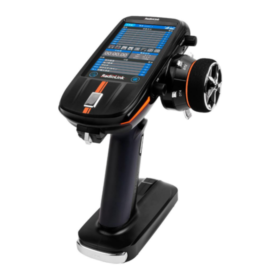
RadioLink RC8X Instruction Manual
Hss, 8-channel digital proportional rc system adaptable to rc cars/boats/robots
Hide thumbs
Also See for RC8X:
- Instruction manual (83 pages) ,
- Quick start manual (15 pages) ,
- Firmware upgrade instructions (6 pages)

Related Manuals for RadioLink RC8X


Summary of Contents for RadioLink RC8X
- Page 1 RC8X (FHSS, 8-Channel Digital Proportional RC System) Adaptable to RC Cars/Boats/Robots Instruction Manual 2022.09...
-
Page 2: Table Of Contents
RadioLink Electronic Limited www.radiolink.com Contents 1. RC8X Remote Control System ..........................4 1.1 Safety Precautions ............................4 1.1.1 Safety Guidelines for Transmitter ....................4 1.1.2 Safety Guidelines for SD Card .......................5 1.2 RC8X Introduction ............................5 1.2.1 Features ..............................5 1.2.2 Specifications ............................6 1.2.3 Package List ............................ - Page 3 RadioLink Electronic Limited www.radiolink.com 2.2.3 Screenshot setting .......................... 54 2.2.4 Timer ..............................58 2.2.5 Lap list ..............................60 2.2.6 Roll out chart ............................ 61 2.2.7 Gear ratio chart ..........................62 2.3 Basic menu ..............................63 2.3.1 Receiver select ..........................63 2.3.2 Child ID mode ..........................64 2.3.3 Servo view ............................65...
- Page 4 RadioLink Electronic Limited www.radiolink.com 2.6.5 Dual ESC mixing ..........................116 2.6.6 CPS mixing ............................119 2.6.7 Tank mixing ............................. 121 2.6.8 Programmable mixing ........................ 123 2.6.9 Tilt mixing ............................126 2.7 Model select ............................... 129 2.8 SD Card Folder ............................131 2.8.1 SD Card Folder Name Introduction ..................131 2.8.2 SD Card Files Copy Methods ....................132...
-
Page 5: Rc8X Remote Control System
RadioLink Electronic Limited www.radiolink.com 1. RC8X Remote Control System 1.1 Safety Precautions 1.1.1 Safety Guidelines for Transmitter Do not operate outdoors on rainy days, run through puddles of water, or use when visibility is limited. Should any type of moisture (water or snow) enter any component of the system, erratic operation and loss of control may occur. -
Page 6: Safety Guidelines For Sd Card
Never power on the RC8X out of 7.0V~17V. 8 pieces AAA batteries,a 2S~4S LiPo battery or a 6S Ni-MH battery is permitted. Never charge the RC8X with the USB port, the Type-C port on the left of RC8X only for firmware upgrade. -
Page 7: Specifications
Multiple Programmable Mix Control such as 4WS, 4WD, Tank mixing, Tilt mixing, CPS mixing etc. RC8X, with steering curve, throttle curve, brake curve, etc., that is an ideal partner for all types RC cars and boats in the market including single-engine and twin-engine models such as... - Page 8 RadioLink Electronic Limited www.radiolink.com Screen 4.3 inches, full-color, backlit LCD touch screen Ground 600 meters(1968.5ft) (Maximum range tested in Control Distance unobstructed areas free of interference) 290mA ± 10mA@8.4V(the LCD screen light on); 200mA ± Operating Current 10mA@8.4V(the LCD screen light off) 7~17V DC (8 pieces of AAA batteries or a 2S-4S LiPo battery or a...
-
Page 9: Package List
Operating Current 30mA Operating Voltage 3-12V Signal Output SBUS&PPM&PWM Compatible RC8X, RC6GS V3, RC6GS V2, RC6GS, RC4GS V3, RC4GS V2, RC4GS, Transmitter T8FB, T8S 1.2.3 Package List RC8XTransmitter×1 R8FGreceiver×1 4G SD Card×1 Lanyard×1 EXT Connect Cable×1 Type-C Cable(for Upgrade) Manual×1... -
Page 10: Recommended Configuration
RadioLink Electronic Limited www.radiolink.com 1.2.4 Recommended Configuration The below accessories sold separately. You can enter the AliExpress Official Store to purchase. Or login to the Radiolink official website www.radiolink.com for product details. FPV monitor holder R7FG Receiver with Gyro Built-in... -
Page 11: Buttons Introduction
RadioLink Electronic Limited www.radiolink.com 1.2.5 Buttons Introduction... -
Page 12: Nomenclature Of Buttons
RadioLink Electronic Limited www.radiolink.com 1.2.6 Nomenclature of Buttons Switch/Knob Full name Function Operation Digital Trim 1 default steering trim Push the button forward to increase the value and press Digital Trim 2 default throttle trim backward button Digital Trim 3 Default dual rate decrease the value. -
Page 13: Icon Introduction
RadioLink Electronic Limited www.radiolink.com Default control CH6, can Push Switch 2 be programmed Default press PS3 to turn Push Switch 3 on or turn off backlight, can be programmed Default control CH7, can Push Switch 4 be programmed Default control CH5, can... -
Page 14: Preparation Before Turn On Transmitter
1.2.8 Preparation before Turn on Transmitter 1.2.8.1 Power for Transmitter RC8X is easily adapted for various battery layouts with wide operating voltage of 7.2V to 17V, which can use 8 pieces of AAA batteries, a 6S Ni-MH battery or a 2S-4S LiPo battery. Universal JST connector with the voltage protection software of Radiolink ensures vital components are protected from a reverse polarity connection. - Page 15 ④ check if the AAA batteries have fully charged. 1.2.8.2 Turn on Transmitter Long press HOME button about 1.5 seconds, the RC8X will shows Radiolink Logo, and the welcome to Radiolink sound is emitted at the same time, the home page will display this information as the picture below: The current model name.
- Page 16 RadioLink Electronic Limited www.radiolink.com Servo operation from CH1 to CH8. Real-time bar-graph display to demonstrate exactly what commands the transmitter is sending to the servos. Mixing function. The background color of functional block will turn to blue if the mixing function corresponding turn on...
-
Page 17: Transmitter Low Voltage Alarm
1.2.8.3 Language Select The language of RC8X is default English, language can be changed in Information Menu. Setting Steps: turn on your RC8X, click the button at the left bottom of RC8X into System menu,... -
Page 18: Compatible Receivers Of Rc8X
(Transmitter Battery Voltage) 1.2.10 Compatible Receivers of RC8X RC8X is packed with a R8FG receiver by default. RC8X is also compatible with 8 channels receiver R8F capable of real-time transmission of RSSI, receiver, and model voltage. 7 channels receiver R7FG, which with gyro integrated. 6 channels receiver R6FG, which with gyro integrated, R6F with HV servo supported. -
Page 19: Receiver Introduction
RC8X and R8FG have finished binding by default. So it’s unnecessary to rebind when you received the new RC8X. Turn on the RC8X and the R8FG, the signal tower will show on the top of the screen as the picture below, it means the transmitter and receiver have get ready to connect the ESC, servo, motor, and other equipment that you are prepared for your car or boat. -
Page 20: Receiver Connection
RadioLink Electronic Limited www.radiolink.com Binding steps: ① Put the transmitter and the receiver close to each other (about 50 centimeters). ② Turn on both the transmitter and the receiver, and then the LED of R8FG will start flashing slowly. ③ There is a black binding button (ID SET) on the side of receiver. - Page 21 5V power supply, and the three wires correspond to “ ”. Note: Radiolink receivers are all designed with anti-polarity connect protection. When the servo cable is plugged reversely, the receiver will not work. The receiver operating voltage is 3V-12V. When the receiver uses a separate battery for independent power supply, the receiver will not be damaged if the battery polarity is reversed, but if the servo is connected at this time, it will cause damage to the servo.
- Page 22 RadioLink Electronic Limited www.radiolink.com connects Telemetry (+-) of R8FG as below picture shown. No extra module is needed. Once connect with success, the returned model voltage will be displayed on the interface of returned flight information. Note Battery connected to Telemetry port is only for 2S-6S battery voltage telemetry, R8FG should be powered supplied by connecting to the CH2 pins on right.
- Page 23 Back: click the button or short press the power button to return to the previous menu. Current: it defaults 0, if the RC8X bind to receiver success, and connect the telemetry cable to the model battery, the real-time model voltage will show here.
-
Page 24: Signal Mode And Gyro Function Of R8Fg
Alarm type: the sound type for alarm, it defaults without any warning tone. But if you want to the RC8X waning you to change the battery when the model battery voltage is lower than the value you have set, there are voice broadcast and 20 types warning tone can be chosen. - Page 25 RadioLink Electronic Limited www.radiolink.com Gyro function setting The integrated high-performance gyro adopts the software filter and PID algorithm, timely and precisely corrects the sensitivity and improve the stability. Its good flexibility to different models and fields easily achieves professional performance even with drift cars.
- Page 26 If you want set DL1/PS3 to control other function, you can set another switch such as PS1 to as the Gain switch setting in the “Channel setting” menu. Setting steps: turn on the RC8X into home page, click the button at the left bottom of...
- Page 27 RadioLink Electronic Limited www.radiolink.com 4) The table below shows how to switch working mode, and enable gyro function on R8FG. R8FG Working Mode Working Mode Mode 1 Mode 2 Mode 3 Mode 4 Note Purple(Red+B Indicator Color Green Blue lue) With Gyro Telemetry Port of Model Battery Voltage(+ -)...
-
Page 28: Installment Of Receiver Antenna
RadioLink Electronic Limited www.radiolink.com R8FG Working Modes & Gyro Phase switch tutorial video https://www.youtube.com/watch?v=VuCaLP3qBR0&t=1s 1.3.5 Installment of Receiver Antenna Please pay attention to the notes below to get the better control distance. Do not cut or bundle the receiver antenna wire. -
Page 29: Rssi Testing
RadioLink Electronic Limited www.radiolink.com Receiver contains some electronic components of high-precision. Be careful to avoid strong vibration and high temperature. Special vibration-proof material for R/C like foam or rubber cloth is used to pack to protect receiver. Keeping the receiver in a well-sealed plastic bag can avoid humidity and dust, which would possibly make the receiver out of control. -
Page 30: Rc8X Basic Functions
If still cannot solve the problem, email to after_service@radiolink.com.cn to get support. 2. RC8X Basic Functions 2.1 System menu setting In System menu, users can set date and time, desktop, system theme, backlight, sound, battery, vibration, LED brightness, home button, external input output, and calibration for wheel,... -
Page 31: Desktop Setting
Setting steps: turn on your RC8X, click the button at the left bottom of RC8X into System menu, click the blue select box named Desktop setting to turn on or turn off the Touch timing function. Tap the button, the background color is blue and the word is ON indicating the Touch timing function is turn on, while the background color is turn to grey and the word is OFF indicating the Touch timing function is turn off. - Page 32 RadioLink Electronic Limited www.radiolink.com color by themselves. The customed colors of theme, background, and font are composed of red, green, and blue. For example, if the values of the three colors of theme are 0, the current border color is black.
-
Page 33: Backlight
RadioLink Electronic Limited www.radiolink.com 2.1.3 Backlight Brightness (Always on): the maximum value of brightness is defaults 100%, tap the value button to adjust the backlight brightness, click “-“ to decrease the brightness and click “+” to increase the brightness. Switch: User can set a switch to turn on or turn off the backlight, PS1, PS2, PS3, PS4, PS5, Steering, Trigger can be select as the switch. -
Page 34: Sound
Alarm only: only broadcast the warning notes that have preset. When the current value same as or smaller than the preset alarm value, the RC8X will broadcast the warning notes, the other operation such as press switch or tap function button will do not trigger any sounds. For example: you have set the transmitter will alarm with sound when the receiver signal is -85 dbm, if the current signal is or less than -85 dbm, the transmitter will broadcast “low receiver signal”... - Page 35 RadioLink Electronic Limited www.radiolink.com other prompt tones are work normal. All: all the prompt tones are working. Normal volume: This function can set the volume of all the prompt tone such as "operation", "warning", “tap button”, "telemetry" etc. The volume is defaults 30%, the minimum volume is 0% which indicate the sound function off, and the maximum volume is 100%.
- Page 36 The speech will be interrupted by the newly triggered content and then the transmitter will go to broadcast the latest content. Setting steps: turn on your RC8X, click the button at the left bottom of RC8X into System menu, or click the blue select box named Sound to set the broadcast sound. click “-“ to...
-
Page 37: Battery (Transmitter Battery Voltage)
RadioLink Electronic Limited www.radiolink.com Reset: click Reset will make the value back to the default number. Back: click the button or short press the power button to return to the previous menu. 2.1.5 Battery (Transmitter Battery Voltage) Current: the real-time transmitter battery voltage will display here when the transmitter is powered by a battery. - Page 38 The auto-off voltage set too high will lead to the battery is not being used effectively, while too low will lead to your battery being over-discharged. Setting steps: turn on your RC8X, click the button at the left bottom of RC8X into System menu, or click the blue select box named Battery to set the transmitter voltage.
-
Page 39: Vibration Setting
“-“ can decrease the value and click “+” can increase the value. Setting steps: turn on your RC8X, click the button at the left bottom of RC8X into System menu, or click the blue select box named Vibration setting to turn on or turn off the vibration function. -
Page 40: Led Setting
If the backlight is turned on, the LED strips will turn on automatically. Setting steps: turn on your RC8X, click the button at the left bottom of RC8X into System menu, or click the blue select box named LED setting to set the brightness and LED type. -
Page 41: Home Button Setting
This function is mainly for the DSC multi-protocol port (the signal output mode setting when using equipments such as simulator, trainer cable, head track, Crossfire, and so on ), USB port, multimedia port working mode selection of RC8X. Multi-protocol output mode: mainly for the signal type required by the device connected to the DSC port of the transmitter. - Page 42 RadioLink Electronic Limited www.radiolink.com Multimedia Mode: Mainly for the working mode setting of the headphone jack of RC8X. Audio output: select this mode when headphones are plugged into the headphone jack. Video input: select this mode when the headphone jack is inserted into a 5.8G video transmission module or other AV analog video signal equipment.
-
Page 43: Calibration
Wheel, trigger, and Rotary knob correction can be applied when a mechanical offset has occurred for some reason. Setting steps: turn on your RC8X, click the button at the left bottom of RC8X into System menu, or click the blue select box named Calibration to calibrate the Wheel, Trigger, and Rotary knob. - Page 44 RadioLink Electronic Limited www.radiolink.com click “Calibration finished”, then the transmitter will automatically return to the “Calibration menu” which means the throttle calibration success. Rotary knob: VR button adjustment Tap “End point” of Rotary knob into the VR button calibration menu, turn the Rotary knob...
-
Page 45: Tools Menu
RadioLink Electronic Limited www.radiolink.com corresponding switch, so each transmitter is slightly different, please ignore it. 2.2 Tools menu 2.2.1 Trim/Dial select Trim/Dial function select: This function is used to assign functions for the transmitter’s digital trimmer button DT1, DT2, DT3, DT4, and dial button DL1. Click at the top right corner to switch the setting menu. - Page 46 4WS front rate, 4WS rear rate, dual ESC, dual ESC ratio, gyro gain, Ackermann, condition. “NULL”: indicate that the function is not enabled. Setting steps: turn on the RC8X, into home page, click the button at the left bottom of...
- Page 47 RadioLink Electronic Limited www.radiolink.com Trim/Dial sound select: Click at the top right corner to switch the setting menu. The sound of button DT1/DT2/DT3/DT4/DL1 can be set in this menu. DTxA: the sound set for pushing the button forward. DTxB: the sound set for pushing the button back.
- Page 48 RadioLink Electronic Limited www.radiolink.com Audition: ON means that the audition will be played automatically after selecting the sound, OFF means that the audition will not be played after the sound is selected. Audio source: indicate the type of sound, “Buzzer”,“Warning voice” ,“System voice”and ,“Customized voice”can be selected.
-
Page 49: Switch Select
RadioLink Electronic Limited www.radiolink.com Stop audition: The button at the bottom of the screen is OFF, and the background color of the select box is grey, indicating that when selecting the buzzer or warning voice, the transmitter will broadcast the prompt tone that you have selected. - Page 50 RadioLink Electronic Limited www.radiolink.com customize the settings, you need to go to the "Channel setting" menu to set the corresponding switch to "NULL", and then back to the “Switch select” menu to set. PS1: The button under the steering wheel, which defaults control CH4, can be customized.
- Page 51 RadioLink Electronic Limited www.radiolink.com (TS) indicates the Throttle Switch The position of the switches on the transmitter, please refer to 1.2.5 Buttons Introduction Dir.: Indicate the direction of the buttons, normal and reverse can be selected. Tap the blue select box to set “Nor.” or “Rev.”, the corresponding servo will display as +100 or -100.
- Page 52 RadioLink Electronic Limited www.radiolink.com Nor.+jog: If set the “Dir.” of the button is “Nor.” and the “Type” is jog, the servo value will reach to +100 from the original value 0 when pressing the button and the servo value will to -100 when loosen.
- Page 53 RadioLink Electronic Limited www.radiolink.com NONE: indicate without any sound when pressing the button, eight types of beeps can be selected. Audio source: indicate the type of sound, “Buzzer” and “Warning voice” can be selected. Beep1-8: buzzer type, eight types can be selected.
- Page 54 RadioLink Electronic Limited www.radiolink.com will broadcast the prompt tone that you have selected. The button at the bottom of the screen is ON, and the background color of the select box is blue, indicating that when selecting the buzzer or warning voice, the transmitter will not broadcast the prompt tone that you have selected.
-
Page 55: Screenshot Setting
Take screenshots for the interface of the transmitter, convenient for users to obtain and share the contents of the transmitters. Setting steps: turn on the RC8X, into home page, click the button at the left bottom of RC8X into System... - Page 56 RadioLink Electronic Limited www.radiolink.com the word “Snapshot successfully!” will display with voice broadcast. The screenshot files will save to the folder named “screenshot” on the SD card. The first screenshot picture will default named “Screenshot_0.bmp”, and the number of the file name will increase by one for each additional picture.
- Page 57 RadioLink Electronic Limited www.radiolink.com 2) click the “screenshot” folder in the U disk to preview the screenshots...
- Page 58 RadioLink Electronic Limited www.radiolink.com 3) click the picture you want to preview...
-
Page 59: Timer
Setting steps: turn on the RC8X, into home page, click the button at the left bottom of RC8X into System... - Page 60 RadioLink Electronic Limited www.radiolink.com Back: click the button or short press the power button to return to the previous menu. Alarm time: the time to trigger the alarm. When the current time reaches the alarm time, the transmitter will alarm. It defaults will alarm at 5 minutes and 0 seconds, which can be customized.
-
Page 61: Lap List
RadioLink Electronic Limited www.radiolink.com should check if the PS1 have been set to control other function in the “Channel setting” menu first, if not, then back to the “Timer” menu to select the PS1 as the timer start switch, if have occupied, select another switch to instead of the PS1 or select another switch as the timer start switch. -
Page 62: Roll Out Chart
RadioLink Electronic Limited www.radiolink.com operation. This function is not available currently, please pay attention to RadioLink official website www.radiolink.com to get the latest firmware to update this function. 2.2.6 Roll out chart This function is designed for pan cars. The roll out chart can be calculated from input values for the number of teeth of the spur gear and pinion gear, and the tire diameter and displayed as a table. -
Page 63: Gear Ratio Chart
“-“ can decrease the value, and click “+” can increase the value, 0.1mm to 1.0mm can be selected. Setting steps: turn on the RC8X, into home page, click the button at the left bottom of RC8X into System menu, click into Tools menu, click the blue select box named Roll out chart to set the parameters for pan cars. -
Page 64: Basic Menu
“-“ can decrease the value, and click “+” can increase the value, 50 to 130 can be selected. Setting steps: turn on the RC8X, into home page, click the button at the left bottom of RC8X into System menu, click into Tools menu, click the blue select box named Gear ratio chart to set the parameters for pan cars. -
Page 65: Child Id Mode
If you are ready to change the receiver, only to bind the RC8X to the receiver you want to use is needed, any setting in this menu is not needed. This page is only used to display the receiver models which compatible with the RC8X. -
Page 66: Servo View
2. Once finished the Child ID mode setting, the corresponding ID number will be displayed on the main interface of RC8X. (For example: ID_1) Change the ID number by click “-“ or “+”, click Reset will make the ID number back to ID_0. -
Page 67: Throttle Mode (Trigger)
This function allows the selection of the forward side and brake (reverse) side operation ratio by changing the neutral position of the throttle servo. Setting steps: turn on the RC8X, into home page, click the button at the left bottom of... - Page 68 RadioLink Electronic Limited www.radiolink.com mode (Trigger) can set the ratio of trigger, the brake rate, and select a switch to control neutral brake. Reset: click Reset will make the value back to the default number. Back: click the button or short press the power button to return to the previous menu.
- Page 69 RadioLink Electronic Limited www.radiolink.com Neutral brake The neutral brake function must specify a switch to turn on or off. The brake rate can be set from 0% to 100%. The neutral brake, which applies the brakes at the neutral position of the throttle trigger, can be set.
-
Page 70: Channel Reverse
This function reverses the direction of operation of the servos related to the transmitter's steering, throttle, channel 3, 4, 5, 6, 7, and 8 operations. CH1 to CH8 are default set as R. Setting steps: turn on the RC8X, into home page, click the button at the left bottom of RC8X into... -
Page 71: Sub Trim
3, 4, 5, 6, 7, and 8 servos. The sub trim of each channel is default 0%, -200% to 200% can be selected. Setting steps: turn on the RC8X, into home page, click the button at the left bottom of RC8X into System... -
Page 72: End Point (Epa)
The left and right sides of each channel can be adjusted independently, the default end point is 100, 0 to 120 can be selected. Setting steps: turn on the RC8X, into home page, click the button at the left bottom of RC8X into... -
Page 73: Fail-Safe
2.3.8 Fail-safe This function sets the servo operation position when transmitter signals cannot be received by the receiver for some reason. Setting steps: turn on the RC8X, into home page, click the button at the left bottom of RC8X into... -
Page 74: Acceleration
RadioLink Electronic Limited www.radiolink.com 2.3.9 Acceleration Neutral: This function is design for adjust the acceleration of throttle when it at the neutral position. Using this function can improve the starting performance of the gasoline engine cars by increasing the neutral speed when the car engine starts. -
Page 75: Condition
TH indicated Throttle BK1 indicated acceleration of Brake1, BK2 indicated acceleration of Brake2, BK3 indicated acceleration of Brake3. Setting steps: turn on the RC8X, into home page, click the button at the left bottom of RC8X into System menu, click into Basic menu, click the blue select box named Acceleration can into the menu to set the throttle acceleration. -
Page 76: Idle Up
There is no linkage locking, etc. Because there is no change near when the neutral position is offset by this function. Setting steps: turn on the RC8X, into home page, click the button at the left bottom of... -
Page 77: D/R, Atl
RadioLink Electronic Limited www.radiolink.com Trim switch: DT1/DT2/DT3/DT4/DL1 can be select to adjust the idle up rate, “NULL”: indicate that no switch to adjust the idle up rate. Function switch: PS1/PS2/PS3/PS4/PS5/Steering/Trigger can be selected to turn on or turn off the idle up function, “NULL”: indicate that no switch selected. - Page 78 DT4. When DT4 is assigned another function, this function can be set with this menu. Setting steps: turn on the RC8X, into home page, click the button at the left bottom of RC8X into System menu, click...
-
Page 79: Channel Limiter
Different from steering rates and brake rates, each channels’ left and right servo travel limits can be adjusted separately. Setting steps: turn on the RC8X, into home page, click the button at the left bottom of RC8X into System menu, click... -
Page 80: Channel Setting
RadioLink Electronic Limited www.radiolink.com servo movement. Click “-“ can decrease the value, and click “+” can increase the value. The initial value is 120%, 0% to 120% can be selected. Reset: click Reset will make the value back to the default number. - Page 81 +100, the higher sensitivity. If the value is 0, it means the gyro function have turned off. Setting steps: turn on the RC8X, into home page, click the button at the left bottom of...
-
Page 82: Telemetry Menu
Other telemetry functions have not yet been available. If you need to add sensor functions later, you can update the the firmware. Setting steps: turn on the RC8X, into home page, click the button at the left bottom of RC8X into... - Page 83 Current signal: the initial value of current signal is -100 dbm. After the RC8X have bind to the receivers which have the signal strength telemetry function, the RSSI value will display here and the value will vary with the distance between the receiver and the transmitter.
- Page 84 Receiver voltage: the input voltage of receiver Current voltage: the initial voltage is 0.0V. When the receiver bind success to the RC8X, the current input voltage of receiver will display here. Alarm sound type: it defaults “NULL”, it means that...
-
Page 85: Voice
RadioLink Electronic Limited www.radiolink.com and Mode3 can be selected. Alarm voltage: the initial voltage is 4.5V, it means that when the current receiver input voltage is lower than 4.5V, the transmitter will alarm, 3.3V to 12V can be selected. Alarm interval: the interval period for alarm, if the current receiver input voltage is lower than the alarm voltage you have set, it defaults alarm once every 10 seconds, the alarm interval time can be customized. -
Page 86: Racing Curve
1 minute, the alarm interval time can be customized. Setting steps: turn on the RC8X, into home page, click the button at the left bottom of RC8X into System menu, click into Telemetry menu, click the blue select box named Voice to enter the setting page. - Page 87 RadioLink Electronic Limited www.radiolink.com EXP curve: It is used to adjust the sensitivity of the direction wheel both in a neutral position and ends. Taking the center line of the EXP as the demarcation point, if set the steering curve type as...
- Page 88 RadioLink Electronic Limited www.radiolink.com If you want to make the steering get the higher sensitivity or make steering more gentle, click “+” to increase the value, or click “-“ to decrease the value. When the value of EXP is not 0%, click Quick or Slow to switch the value quickly.
-
Page 89: Throttle Curve
RadioLink Electronic Limited www.radiolink.com If you want to make the steering get the higher sensitivity or make steering more gentle, click “+” to increase the value, or click “-“ to decrease the value. When the value of VTR is not 0%, click Quick or Slow to switch the value quickly. - Page 90 RadioLink Electronic Limited www.radiolink.com Quick/Slow: +100 indicates the quick throttle curve rate, and -100 indicates the slow throttle curve rate. The vertical cursor line moves in conjunction with the operation of the throttle trigger. EXP rate: the initial value of EXP rate is 0%, -100% to +100% can be selected.
- Page 91 RadioLink Electronic Limited www.radiolink.com high side direction servo operation quicker or milder, click “+” to increase the value, or click “-“ to decrease the value. When the value of EXP is not 0%, click Quick or Slow to switch the value quickly.
-
Page 92: Brake Curve
RadioLink Electronic Limited www.radiolink.com Setting steps: turn on the RC8X, into home page, click the button at the left bottom of RC8X into System menu, click into Racing curve menu, click the blue select box named Throttle curve into the menu to set the throttle curve type. The vertical cursor line moves in conjunction with the operation of the steering wheel. -
Page 93: Steering Speed
RadioLink Electronic Limited www.radiolink.com 2.5.4 Steering speed Quick steering operation will cause momentary understeering, loss of speed, or spinning. Steering speed function will very helpful in such cases. - Page 94 4. The steering speed "Turn" and "Return" adjustment can be controlled with digital trim DT1 to DT4 or digital dial DL1 etc. with the Trim/Dial select function in Tools menu. Setting steps: turn on the RC8X, into home page, click the button at the left bottom of...
-
Page 95: Throttle Speed
RadioLink Electronic Limited www.radiolink.com Reset: click Reset will make the value back to the default number. Back: click the button or short press the power button to return to the previous menu. 2.5.5 Throttle speed Sudden throttle trigger operation on a slippery road will cause the wheels to spin and the vehicle cannot accelerate smoothly. - Page 96 RadioLink Electronic Limited www.radiolink.com Attention: Throttle servo (ESC) operation is delayed so that the drive wheels will not spin even if the throttle trigger is operated more than necessary. This delay function is not performed when the throttle trigger is returned and at brake operation.
- Page 97 RadioLink Electronic Limited www.radiolink.com High-Low point:A delay can be set in 2 ranges with Point 1 as the boundary. Turn : "Low" and "High" turn direction delay adjustment, the initial value of High or Low turn speed is 100, 1 to 100 can be selected, if the value is 100, it means there is no delay.
- Page 98 Setting the speed function in the return direction slows the deceleration of the car body, so please be careful to set it carefully. Setting steps: turn on the RC8X, into home page, click the button at the left bottom of...
-
Page 99: Traction Control (T.r.c)
RadioLink Electronic Limited www.radiolink.com 2.5.6 Traction control (T.R.C) Trigger operation with cornering on a slippery road surface is hard to get traction and smooth cornering cannot be done. By intermittently operating the throttle, you can smoothly navigate and travel on topological lines. Also, with a drift car, by... - Page 100 RadioLink Electronic Limited www.radiolink.com Throttle return: Set the ratio that the servo returns to the slow side of trigger operation. If set to 0%, the traction control function will not work. At 50%, it returns to the neutral position at 50% (half), 100% of the trigger operation amount.
-
Page 101: 100
The traction control can be select the switch PS1, PS2, PS3, PS4, PS5, Steering switch, and Trigger switch to turn on or turn off, the switch can select in Switch select menu. Setting steps: turn on the RC8X, into home page, click the button at the left bottom of... - Page 102 RadioLink Electronic Limited www.radiolink.com A.B.S: The button at the right of “A.B.S” is ON, and the background color of the select box is blue, indicating that the A.B.S function is turn on. Push forward the throttle trigger to trigger the A.B.S function.
- Page 103 RadioLink Electronic Limited www.radiolink.com occupied or not in the “Channel setting” menu. If occupied, please change another channel. Brake return: Sets the rate that the trigger operation corresponds to the servo returns to position when brake release. When set to 0%, the A.B.S function is not performed. When set to 50%, the servo returns 50% (1/2) of the trigger operation amount and when set to 100%, the servo returns to the neutral position.
-
Page 104: Start
3 (brake 2 and 3 are auxiliary channels). Brake mixing can be set under the mixing menu. Brake 1, 2, 3 can be adjusted independently except the trigger point of the setting item. Setting steps: turn on the RC8X, into home page, click the button at the left bottom of... - Page 105 RadioLink Electronic Limited www.radiolink.com set throttle position to a preset point so that the tires do not lose their grip and the car accelerates smoothly. Attention: 1. When the throttle trigger moves to the trigger point, the throttle servo moves to the preset point position.
-
Page 106: Engine Cut
“Trigger point”, the throttle servo will accelerate to the set speed automatically. It is canceled when the throttle trigger is returned. Setting steps: turn on the RC8X, into home page, click the button at the left bottom of... - Page 107 Engine cut function is turned on, the throttle servo (motor) value is locked in the preset position and does not operate even if the throttle trigger is operated. Setting steps: turn on the RC8X, into home page, click the button at the left bottom of...
-
Page 108: Mixing Menu
RadioLink Electronic Limited www.radiolink.com RC8X into System menu, click into Racing curve menu, click the blue select box named Engine cut into the menu to set it. Click “-“ to decrease the value and click “+” to increase the value. - Page 109 RadioLink Electronic Limited www.radiolink.com (Steering mixing menu). Mixing: The button at the right of “Mixing” is OFF, and the background color of the select box is grey, indicating that the Steering mixing function is turn off. The button at the right of “Mixing”...
-
Page 110: Brake Mixing
Brake rate: is for the brake angle adjustment. The initial value is 0%, -120% to 120% can be selected. Setting steps: turn on the RC8X into home page, click the button at the left bottom of RC8X into System menu, click into Mixing menu, click the blue select box named Steering mixing into the menu to set it. - Page 111 RadioLink Electronic Limited www.radiolink.com select box is blue, indicating that the Brake1/Brake2 mixing function is on. Brake channel: the Brake1 is default controlled by channel2, Brake2 and Brake3 can be customized, channel 1 and channel 8 can be selected. Brake rate: is for the brake rudder amount adjustment.
-
Page 112: Gyro Mixing
(Trigger) menu, the brake side operation will stop to working. When using the brake mixing function, set the trigger mode to Forward 70: Brake 30 or Forward 50: Brake 50. Setting steps: turn on the RC8X into home page, click the button at the left bottom of... - Page 113 RadioLink Electronic Limited www.radiolink.com Gyro type: Gyro mixing type selection. Gyro built-in, Gain1, Gain2, and Gain4 can be selected. 1) Gyro built-in: it means the current working gyro is the built-in gyroscope of the receiver. How to make the gyro function of the receiver R8FG enabled? Please refer to: 1.3.4 Signal Mode and Gyro...
- Page 114 RadioLink Electronic Limited www.radiolink.com Gain2: a group gyro gains, can switching from Gain1 and Gain2 Gain4: two groups gyro gains, 2 gains can be set in one group, can switching from Gain1 and Gain2, Gain3 and Gain4. Gain mode: Normal and AVSC mode can be selected. The AVCS mode increases straight running stability more than that of the Normal mode.
-
Page 115: 4Ws Mixing
RadioLink Electronic Limited www.radiolink.com Gain type switch: if the Gyro type selected Gain2 or Gain4, a switch should be set to switching between Gain1 and Gain2 or Gain3 and Gain4. PS1/PS2/PS3/PS4/PS5/Steering/Trigger can be selected. If the Gain type switch selects “NULL”, then only one gain of each group can be selected at a time. - Page 116 RadioLink Electronic Limited www.radiolink.com 4WS type: four types can be selected. Type1: Function OFF (front only) Type2: switching between front side only and front side normal but rear side reverse phase Type3: switching from front side only, front side normal but rear side reverse phase, and...
-
Page 117: Dual Esc Mixing
For example: if set the Front switch is PS2, when press the PS2, the 4WS type will switch to the type that front side only from other types. Setting steps: turn on the RC8X into home page, click the button at the left bottom of... - Page 118 RadioLink Electronic Limited www.radiolink.com to trigger one of the Dual ESC types. Trigger ratio is suggested to set as Forward 50: Brake 50. Dual ESC mixing Mixing: The button at the right of “Mixing” is OFF, and the background color of the select box is grey, indicating that the Dual ESC mixing function is turn off.
- Page 119 RadioLink Electronic Limited www.radiolink.com ESC1 rate/ESC2 rate: Adjust the front and rear motor controller operation amount by click “+” and “-“, by pressing the button “+” to adjust the rate of ESC2 and by pressing the button “-“ to adjust the rate of ESC1 when both the value of ESC1 and ESC2 are 100% (the initial value).
-
Page 120: Cps Mixing
Radiolink will not be responsible for motor controller, motor, and other vehicle trouble due to the use of this function. Setting steps: turn on the RC8X into home page, click the button... - Page 121 RadioLink Electronic Limited www.radiolink.com CPS mixing1/2/3/4 Mixing: The button at the right of “Mixing” is OFF, and the background color of the select box is grey, indicating that the CPS mixing function is turn off. The button at the right of “Mixing”...
-
Page 122: Tank Mixing
Point1 plus the absolute value of Point2 do not less than 95. The details value must depend on your LEDs. Setting steps: turn on the RC8X into home page, click the button at the left bottom of... - Page 123 RadioLink Electronic Limited www.radiolink.com “Mixing” is ON, and the background color of the select box is blue, indicating that the Tank mixing function is turn on. Mixing channel: the channels select to connect the left and right motors. Mixing rate (Forward/Back): is for forward/backward rate adjustment.
-
Page 124: Programmable Mixing
③ Operating the steering wheel while operating the trigger to the brake side will operate the same as the forward side in the reverse direction. Setting steps: turn on the RC8X into home page, click the button at the left bottom of... - Page 125 RadioLink Electronic Limited www.radiolink.com EXP curve: Quick/Slow: is for the rate of EXP/VTR/Multiple point curve. 0% to 100% indicates the quick EXP/VTR/Multiple point rate, and -1% to -100 indicates the slow EXP/VTR/Multiple point rate. The vertical cursor line moves in conjunction with the changes of the curve rate value.
- Page 126 RadioLink Electronic Limited www.radiolink.com 120% can be selected. Right: for right, brake or down side mixing amount adjustment. The initial value is 50%, -120% to 120% can be selected. Program. Mixing1 Click at the top right corner to switch the first programmable mixing setting page to the second programmable mixing setting page.
-
Page 127: Tilt Mixing
Setting steps: turn on the RC8X into home page, click the button at the left bottom of RC8X into System menu, click into Mixing menu, click the blue select box named Programmable mixing into the menu to set it. - Page 128 RadioLink Electronic Limited www.radiolink.com box is grey, indicating that the Tilt mixing function is turn off. The button at the right of “Mixing” is ON, and the background color of the select box is blue, indicating that the Tilt mixing function is turn on.
- Page 129 FLP->RUD: DT1/DT2/DT3/DT4/DL1 can be selected to adjust the mixing amount from flap to rudder. Setting steps: turn on the RC8X into home page, click the button at the left bottom of RC8X into System menu, click into Mixing menu, click the blue select box named Tilt...
-
Page 130: Model Select
2.7 Model select 200 models’ data can be saved in the transmitter RC8X. The name of every model can be renamed, and the factory settings of every model can be reset in this menu. Data can be copied and pasted between every two models. Click the model that needs to be set, and the following settings will appear on the screen: Model select: model memory selection. - Page 131 RadioLink Electronic Limited www.radiolink.com the character of the model name you want to set or change, click “Confirm” at the bottom of the screen to save the setting. Attention: when you click “Paste model”, a question “Copy data error. Please copy again!”...
-
Page 132: Sd Card Folder
Icon of desktop FONT Font of RC8X Cache file Cache file font library, the RC8X will cannot power on if Battery Cache file delete the SIF folder Icon All the Icons in RC8X 4 Wheel Steering Signal Icon of signal Screenshot Screenshot... -
Page 133: Sd Card Files Copy Methods
2.8.2 SD Card Files Copy Methods 1) Copy the files with a card reader ① power off the RC8X, remove the SD card from RC8X, insert the SD card to a card reader, connect the card reader to the USB port of the computer. - Page 134 Introduction about the nomenclatures that on the update setting menu SD Size: the capacity of the SD card, if you replace a larger capacity SD card, the RC8X and computer connection will take longer to read the transmitter device information, about 2...
- Page 135 Update the latest: update the latest firmware that saved in the SD card of RC8X Upgrade the specified: update the specified firmware that saved in the SD card of RC8X Power off: exit the update setting menu and the RC8X will turn off at the same time. The setting steps as below: keep the RC8X power off, use a USB cable (type-c) connect the RC8X to the computer.
- Page 136 Short press the "power button" to enter the USB mode, and the computer will also remind that a U disk is inserted. The computer usually displays two removable disks. RC8X-EXT refers to SD card, RC8X-INH refers to remote control. Copy the firmware to the RC8X-EXT disk.
- Page 137 RadioLink Electronic Limited www.radiolink.com Note: During the copying process, when it pops the reminder, please choose “copy and replace”and then click “YES”. After the firmware copy is complete, press PS3 button to return to the previous menu. Then turn DL1 knob to turn the yellow background cursor to “power off”, and then short press...
-
Page 138: Note For Sd Card Content Modification
2) All filenames in the SD card only support English. If you change the filename to other languages, the filename will display garbled characters. 3) If the SD card is pulled out and then insert into the RC8X, the RC8X needs to be restarted to see the modified contents in the SD card. -
Page 139: Reset System Settings
RadioLink Electronic Limited www.radiolink.com 2.9.3 Reset system settings The reset system settings function will make all the settings except the calibrate reset back to the factory settings. Click button “Reset system settings”, click “Confirm” when the question “Are you sure to reset system settings?”... -
Page 140: Modifying For Left-Hand Use
The wheel section left and right installation direction can be reversed. The wheel is default at the right of RC8X, users can reinstall it by a Phillips screwdriver. The following operation takes the right-hand use modify to the left-hand use as an example: 2.10.1 Remove the Wheel... -
Page 141: Remove The Wheel Installation Port Cover
Use the Phillips screwdriver to remove the two mounting screws (HA3.0*12mm screws) on the left wheel installation port cover. Gently pull off the left wheel installation port cover. Gently pull out the USB port motherboard. Remove the cable from the RC8X PCB board. -
Page 142: Install Wheel
Insert the 14pin plug, 3pin plug and 4pin plug on the steering wheel into the corresponding socket in the middle of the PCB motherboard on the left side of the RC8X. Insert the plastic steering mounting plate. When inserting part of it, gently insert the extra part of the 3 connector wires into the interlayer of the RC8X PCB board. -
Page 143: Install The Wheel Installation Port Cover
Insert the 11pin plug on the plate into the corresponding port of the PCB motherboard on the right side of the RC8X. Gently insert the extra part of the wire into the interlayer of the RC8X PCB board. Insert the black plastic steering mounting plate into the corresponding wheel installation port. - Page 144 RadioLink Electronic Limited www.radiolink.com The picture is as follows after modifying the wheel from the right to the right:...
-
Page 145: Wheel Or Trigger Mechanical Adjustment
2.11 Wheel or Trigger Mechanical Adjustment The wheel or trigger of RC8X can be adjusted mechanically according to your needs. 2.11.1 Trigger brake lever adjustment Make this adjustment when you want to decrease the stroke of the brake side of the throttle trigger for operation feel. -
Page 146: Trigger Tension Screw Adjustment
RadioLink Electronic Limited www.radiolink.com 2.11.2 Trigger tension screw adjustment Adjust the trigger tension screw when you want to change the tension of trigger spring. Adjustment steps: Using a 1.5mm hex wrench, loosen the trigger tension screw (1.5mm) by turning it slightly counterclockwise. -
Page 147: Wheel Tension Screw Adjustment
RadioLink Electronic Limited www.radiolink.com Adjustment steps: Using a 2.0mm hex wrench, loosen the trigger slide mounting screw (2.0mm) by turning it slightly counterclockwise. If the trigger slide screw is turned too much, the screw may fall out. 2.11.4 Wheel tension screw adjustment... -
Page 148: Firmware Update
Using a 1.5mm hex wrench, loosen the trigger tension screw (1.5mm) by turning it slightly counterclockwise. If the trigger tension screw is turned too much, the screw may fall out. 2.12 Firmware Update RC8X will keep to update the firmware to add new functions. Please pay attention to our website www.radiolink.com to get the latest firmware. - Page 149 RadioLink Electronic Limited www.radiolink.com >Push DT1 and DT2 TRIM buttons to the middle at the same time, and then long press the power button to enter the data copy and upgrade mode. The computer will pop out that a USB drive is inserted.
- Page 150 RadioLink Electronic Limited www.radiolink.com ③ upgrade the latest firmware > short press the power button into the “Update the latest” mode, short press the power button again to upgrade. > “being updated” pop out at the bottom of the screen means the firmware is updating.
- Page 151 “firmware reads fail!” pop out at the bottom of the screen means the transmitter RC8X have not find out the firmware from the microSD card, please copy the latest firmware to the microSD card first, and then reupdate follow the steps above.
- Page 152 RadioLink Electronic Limited www.radiolink.com ② select update mode > The following four options will appear on the screen, and "USB MODEL" is selected by default. > Turn DL1 knob to turn the yellow background cursor to “Update the specified” ③ upgrade the specified firmware >...
- Page 153 RadioLink Electronic Limited www.radiolink.com > “being updated” pop out at the bottom of the screen means the firmware is updating. ④ “update successfully” pop out at the bottom of the screen means the firmware upgrade is successful. ⑤ exit the update mode...
- Page 154 RadioLink Electronic Limited www.radiolink.com > Press PS3 button to return to the previous menu. > Turn DL1 knob to turn the yellow background cursor to “power off”. > Short press the power button to exit the upgrade mode.
-
Page 155: Thanks
3. If the product is purchased from the local distributor, you can also ask them for support and repair as prefer. A 4G SD card will be packed with RC8X, it can be used for transmitter upgrade or save the font, icon, screenshot, sound, and other customized files you have designed for your RC8X.
Need help?
Do you have a question about the RC8X and is the answer not in the manual?
Questions and answers