Table of Contents
Advertisement
Quick Links
Advertisement
Table of Contents

Related Manuals for Delta DVPDNET-SL


Summary of Contents for Delta DVPDNET-SL
- Page 1 DVPDNET-SL DeviceNet Network Scanner Operation Manual DVP-0204520-04 2022-7-15...
-
Page 3: Table Of Contents
This operation manual provides functional specifications, installation, basic operation and settings, as well as an introduction to relevant network protocols. DVPDNET-SL is an OPEN TYPE device. Therefore it should be installed in an enclosure free of airborne dust, humidity, electric shock and vibration. The enclosure should prevent non-maintenance staff from operating the device (e.g. - Page 4 6.1 Principle of Bit-Strobe ..................23 DISPLAY OF NODE STATUS ON NETWORK ............24 7.1 Display of Status of Nodes in Scan List ..............24 7.2 Status of DVPDNET-SL ..................24 SETUP OF SLAVE MODE ..................25 SETUP OF EXTENDED BAUD RATE ..............27 9.1 Setup of Extended Baud Rate (in Master Mode) ............
-
Page 5: Introduction
Thank you for choosing Delta DVPDNET-SL. To ensure correct installation and operation of DVPDNET-SL, please read this chapter carefully before using your DVPDNET-SL. DVPDNET-SL running on the left side of PLC can serve as the DeviceNet master or slave with PLC MPU together. It can be configured through DeviceNet software. -
Page 6: Specifications
DeviceNet Network Scanner DVPDNET-SL Specifications PLC that DVPDNET-SL supports Item Specification DVPDNET-SL supports the PLC which can be extendable on its left side PLC Model (E.g. DVP-SV, DVP-EH2_L, DVP-SX2, DVP-SA2, DVP10MC11T, DVP-SV3 and DVP-SX3 and etc.) DeviceNet Interface Item... -
Page 7: Product Profile & Outline
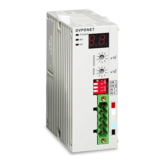
DeviceNet Network Scanner DVPDNET-SL 2 Product Profile & Outline Dimension DVPDNET DR 1 DR 0 IN 1 IN 0 Product Profile 1. Model name 2. Extension port 3. Power, MS and NS LED indicators 4. DIN rail clip 5. Digital indicator 6. -
Page 8: Address Switch
DeviceNet Network Scanner DVPDNET-SL Address Switch The switch is used for setting up the node address of DVPDNET-SL on the DeviceNet network. Range: 00 ~ 63 (64 ~ 99 are forbidden). Switch setting Content 0 … 63 Valid DeviceNet node address 64…99... -
Page 9: Digital Indicator
03. When the error codes such as "E7" and "E1" are on display, please refer to Section 11.2 for correction. Extension Port The extension port is mainly used on connecting DVPDNET-SL to the PLC. DVP-PLC Operation Manual... -
Page 10: Installation
Open the DIN rail clip on the PLC and DVPDNET-SL. Insert the PLC and DVPDNET-SL onto the DIN rail. Clip up the DIN rail clips on the PLC and DVPDNET-SL to fix the PLC and DVPDNET-SL on the DIN rail, as shown below. -
Page 11: Connecting To Devicenet Connection Port
The colors on the PINs on the DeviceNet connection port match the colors of the connection cables. Make sure you connect the cable to the right PIN. We recommend you also apply Delta’s power module in the connection. DVP-PLC Operation Manual... -
Page 12: Configuration Of Dvpdnet-Sl
4.1.1 Selection of Communication Channel Max 8 DVPDNET-SL modules can be connected to the left side of the PLC and every DVPDNET-SL is a communication channel. When there are three DVPDNET-SL modules connected to PLC’s left side and DeviceNet Builder software is online, the following dialog box will pop up for selecting the current channel. -
Page 13: Setup Of Scan Module
DeviceNet Network Scanner DVPDNET-SL 4.1.2 Setup of Scan Module The following dialog is for setting DVPDNET-SL’s current mode: master mode or slave mode. Parameter Explanation Master mode For setting DVPDNET-SL as master. The cycle time for master to send and receive the real time data Scan interval time after real-time data connection is successful. -
Page 14: Setup Of Scan List
DeviceNet Network Scanner DVPDNET-SL 4.1.3 Setup of Scan List Double click the existing icon of DVPDNET-SL in the DeviceNet Builder interface and then the following dialog box appears for configuring the scan module. Parameter Explanation All already scanned slaves appear in “Available list”. -
Page 15: Input Table And Output Table
DeviceNet Network Scanner DVPDNET-SL 4.1.4 Input Table and Output Table Select the device in “Scan list” and then the data length of input and output of the device will be displayed respectively in the lower part of the following dialog box. -
Page 16: Input And Output Mapping Areas
When the PLC is DVP-SV3 and DVP-SX3, registers D16000~D19999 are occupied. The number of the first DVPDNET-SL on the left side of the PLC is 1 and the number of the DVPDNET-SL module close to the left side of the first DVPDNET-SL is 2, and subsequent and so on. -
Page 17: I/O Mapping Area Assignment (In Master Mode)
Note: If the number of the DVPDNET-SL is 2, the numbers of the registers in the two tables above will all be added by 500 respectively; if the number of the DVPDNET-SL is 3, the numbers of the registers in the two tables above will all be added by 1000 respectively;... -
Page 18: I/O Mapping Area Assignment (In Slave Mode)
PLC’s devices among which D6250 is the initial device will be automatically sent back to DeviceNet master. In this way, the real-time data exchange is realized. When the PLC is DVP-SV3 or DVP-SX3, and the DVPDNET-SL is in slave mode, the data mapping areas ... -
Page 19: Sending Explicit Message From Ladder Diagram
②: Then DVPDNET-SL transfers the request message to the target equipment. ③: The target equipment processes the request message and replies with a response message to DVPDNET-SL. ④: The PLC stores the response message from DVPDNET-SL to D register to finish one explicit message transmission. DVP-PLC Operation Manual... -
Page 20: Structure Of Explicit Message
See the table below for the corresponding relation between the two areas and PLC devices. If you transmit the request message to be sent out to D6250 ~ D6281, DVPDNET-SL will fill the response message data to D6000 ~ D6031. - Page 21 Before sending the explicit message by using WPL program, we suggest you clear the request message editing area and response message editing area to 0. If the slave responds with a standard error code, and DVPDNET-SL consider the communication successful, “The communication of the explicit message is successful.” indicates that the communication has been completed successfully.
- Page 22 S TOP Node Address:00 DeviceNet Node Address:02 RJ12 Note: Delta DeviceNet slave module, IFD9502 can connect VFD AC motor drive to the DeviceNet network. 2> Parameters setting and devices explanation Settings for DVPDNET-SL Parameter Setting value Explanation Node address Set the node address of the DVPDNET-SL to “00”.
- Page 23 Attribute 1 of the target equipment (node address: 02). If the communication of the explicit message is successful, the slave will send back a response message. When M0 is On, DVPDNET-SL only sends out the request message once. To send out the request ...
- Page 24 M1 = On, set 0x99>>Instance 1>>Attribute 2 of IFD9502 to “0004Hex”. 1> Connection Figure Note: Delta DeviceNet slave module, IFD9502 can connect the temperature controller to the DeviceNet network. 2> Parameters setting and devices explanation Settings for DVPDNET-SL Parameter...
- Page 25 request message editing area to 0. When M1 is On, DVPDNET-SL sends out the request message. Write 0004 Hex into Class 99 >> Instance 1 >> Attribute 2 of the target equipment (node address: 02). If the communication of the explicit message is successful, the slave will send back a response message.
- Page 26 DeviceNet Network Scanner DVPDNET-SL When M1 is On, DVPDNET-SL only sends out the request message once. To send out the request message again, you will have to change the value of ReqID. If the writing is successful, the message back from the target equipment will be stored in D6000 ~ ...
-
Page 27: Bit-Strobe Command
DeviceNet Network Scanner DVPDNET-SL 6 Bit-Strobe Command Principle of Bit-Strobe Bit-strobe is one of the standard I/O transmission methods for DeviceNet. The size of the command is fixed to 8 bytes (i.e. 64 bits), and every bit corresponds to a slave. -
Page 28: Display Of Node Status On Network
D6036 is 0. While DVPDNET-SL is being initialized, the value in the high byte of D6036 is 1 and the low byte is 0. When an error occurs in DVPDNET-SL, the value in the high byte of D6036 is 2 and the low byte contains an error code. -
Page 29: Setup Of Slave Mode
8 Setup of Slave Mode DVPDNET-SL can serve as slave through modifying the mode in the software. As DVPDNET-SL serves as slave, the default input / output data length is 8 bytes and max input / output data length is 255 bytes. - Page 30 Select “Network” >> “Download” and then below dialog box appears. Click on “Y” to download the configuration data to DVPDNET-SL. After download is finished, power PLC off and then repower it. At this time, DVPDNET-SL has been set as slave mode.
-
Page 31: Setup Of Extended Baud Rate
DeviceNet Network Scanner DVPDNET-SL 9 Setup of Extended Baud Rate Setup of Extended Baud Rate (in Master Mode) Connect the device to the Devicenet network according to the following figure. The PC accesses the PLC via RS232 or RS485. DVPDNET-SL... - Page 32 Select “Network” => “Download” and the following dialog box appears. Click “OK” to download the configuration data to DVPDNET-SL. After download is completed, set DVPDNET-SL’s function switch DR0 and DR1 as ON and then repower PLC to finish the setting of the extended baud rate.
-
Page 33: Setup Of Extended Baud Rate (In Slave Mode)
DVPDNET-SL(Slave) Note: a. The DVPDNET-SL at the bottom of the figure above has been set to work in slave mode. b. The node addresses of the two DVPDNET-SLs must not be identical. (See Section 2.4). c. The baud rates of the two DVPDNET-SLs are both 500K bps (See Section 2.5). - Page 34 DeviceNet Network Scanner DVPDNET-SL 3) Set up the communication parameters for the PC and DVP-SV, e.g. the communication port, address, baud rate and communication format. Click on “OK” after the configuration is finished. Item Function Default COM port on the PC to be used to communicate...
- Page 35 DVPDNET-SL (Slave). “Download” to download the newly set parameter value to 7) After the download is completed, set DVPDNET-SL (Slave)’s function switch: DR0 and DR1 as ON. And then repower PLC to finish the setting of the extended baud rate.
-
Page 36: Application Example
STOP RS232 DeviceNet RTU-DNET VFD -L V FD-L RS485 Note: Delta DeviceNet remote IO communication module, RTU-DNET supports the MODBUS communication function. VFD-L according to the table below. Set up DVPDNET-SL, RTU-DNET and DeviceNet Module Node address Baud rate DVPDNET-SL... -
Page 37: How To Configure Devicenet Network
DeviceNet Network Scanner DVPDNET-SL VFD-L Setting Description parameter 02-00 Transmit the frequency of VFD-L via RS485. 02-01 Control the operation of VFD-L via RS485. 09-00 Set the node address of VFD-L in Modbus to 1. 09-01 Set the baud rate of VFD-L in Modbus to 9600... - Page 38 See the figure below, in which RTU-DNET are the node addresses of DVPDNET-SL and 01 and 02 respectively. DVP-PLC Operation Manual...
- Page 39 DeviceNet Network Scanner DVPDNET-SL 5> Double click on RTU-DNET (node 02), and the "Node Configuration…” dialog box will appear. 6> Clicking on “IO Configure…” button in “Node Configuration” dialog box, you will see “RTU Configuration” page where you click on “Scan IO” button and “Warning” dialog box will appear. With a click on “OK”, DeviceNet Builder will detect the devices connected to RTU-DNET as below.
- Page 40 DeviceNet Network Scanner DVPDNET-SL 8> In the interface of “Modbus gateway setting”, use the parameters of one slave and fill in relevant values there. You can refer to the user manual of RTU-DNET. Note: The slave mentioned here is the slave on the Modbus network and has nothing directly to do with the DeviceNet network.
- Page 41 DeviceNet Network Scanner DVPDNET-SL Configuration of DeviceNet Master 1> Double click on DNET Scanner (node 01), and the “Scan Module Configuration..." dialog box will pop up. You can find the currently available nodes, RTU-DNET and VFD-B Drives 230V 3HP, in the list on the left side.
- Page 42 DeviceNet Network Scanner DVPDNET-SL 3> Confirm all the settings and click on “OK”. Next, download the configuration to DVPDNET-SL. If DVP-SV is in RUN mode while you are downloading the configuration, a “Warning” dialog box will appear. 4> Click on “OK” to continue the download. Make sure DVP-SV is in RUN mode.
-
Page 43: Ladder Diagram Program
DeviceNet Network Scanner DVPDNET-SL 10.3 Ladder Diagram Program This section introduces how to edit the ladder diagram program to meet the requirement of controlling the DeviceNet network. When X0=ON, VFD-L AC motor drive runs; Control When X1=ON, VFD-L AC motor drive stops;... -
Page 44: Error Diagnosis & Trouble-Shooting
DeviceNet Network Scanner DVPDNET-SL 11 Error Diagnosis & Trouble-shooting DVPDNET-SL supports two diagnostic methods: indicator diagnosis and digital display diagnosis. DVPDNET POWER 11.1 LED Indicator Diagnosis POWER LED LED status Indication How to correct The power supply is Make sure that the power supply to DVPDNET-SL is abnormal. -
Page 45: Digital Display Diagnosis
DVPDNET-SL (in normal operation) DVPDNET-SL is in STOP Turn the PLC to RUN to start I/O data exchange. status. 1. Ensure that the node address of DVPDNET-SL is Duplicated MAC ID check unique. failure 2. Re-power DVPDNET-SL. No slave device in the scan Configure the scan list and download it to list. - Page 46 3. Check if the baud rates of the node devices on the network are identical. 4. Check if the communication cable is normal so as to avoid that the cable is disconnected or connected loosely. 5. Re-power the DVPDNET-SL module. DVP-PLC Operation Manual...
Need help?
Do you have a question about the DVPDNET-SL and is the answer not in the manual?
Questions and answers