
Related Manuals for Index R200


Summary of Contents for Index R200
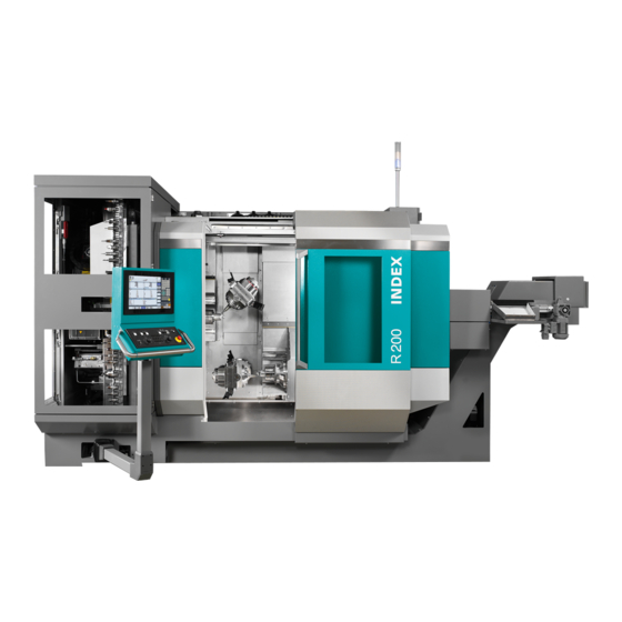
- Page 1 OPERATING INSTRUCTIONS Maintenance Instructions Maintenance Instructions R200 LR1702.10181 - 05.06.2019 05.06.2019/Sp/Wartungsanleitung/20057609...
- Page 2 This document is proprietary and was originally written in German. Its reproduction and distribution in whole or in individual parts without permission of the copyright owner is prohibited and will be prosecuted under criminal or civil law. All rights reserved, including for translation. © Copyright by INDEX-Werke GmbH & Co. KG Hahn & Tessky...
-
Page 3: Table Of Contents
A260 - Cleaning the chip conveyor........................32 A270 - Maintenance on non-contact tool monitoring system Renishaw NC-4............35 A280 - Clean labyrinth ring of spindles........................37 A285 - Clean spindle cover of the motorized milling spindle (labyrinth ring)............38 Maintenance Instructions R200 LR1702.10181 - 05.06.2019... - Page 4 D370 - Check and potentially replace the end position dampers................99 D440 - Replacing hydraulic fluid..........................101 D500 - Perform data backup..........................105 D520 - Check control cabinet and cable assemblies (visual inspection)............. 106 D640 - Check setting of electrical fuses......................108 Maintenance Instructions R200 LR1702.10181 - 05.06.2019...
- Page 5 Service Interval - 5 Years............................109 Maintenance Summary - 5 Years........................110 I020 - Replace the pressure accumulator......................111 Service Interval - 8 Years............................113 Maintenance Summary - 8 Years........................114 J120 - Replacing the viewing glass........................115 Maintenance Instructions R200 LR1702.10181 - 05.06.2019...
- Page 6 Table of contents Maintenance Instructions R200 LR1702.10181 - 05.06.2019...
-
Page 7: Preface
Cleaning with a pressure washer results in strong corrosion. Furthermore, bearings may be degreased and seals may become leaking, which can lead to safety problems. A suitable cleaning tool must be used to clean the hole in the tool mounting. Maintenance Instructions R200 LR1702.10181 - 05.06.2019... -
Page 8: Safety Instructions
Damaged power supply and fluid lines must be replaced immediately. It may be necessary to remove or disable protective equipment to carry out repairs. Any removed protective equipment must be reinstalled immediately after finishing the repair. Maintenance Instructions R200 LR1702.10181 - 05.06.2019... - Page 9 “Safety instructions for CNC turning machines” must be observed. The safety precautions, as a separate document, are part of the INDEX-TRAUB user documentation. When carrying out maintenance work on fluid systems, (hydraulic, lubrication, and pneumatic systems), make sure before starting the work that the respective system has been depressurized.
- Page 10 Preface Maintenance Instructions R200 LR1702.10181 - 05.06.2019...
-
Page 11: Service Interval - Care Activities
Service Interval - Care activities Service Interval - Care activities Maintenance Instructions R200 LR1702.10181 - 05.06.2019... -
Page 12: Maintenance Summary - Care Activities
- Cleaning the chip conveyor A270 - Maintenance on non-contact tool monitoring system Renishaw NC-4 A280 - Clean labyrinth ring of spindles A285 - Clean spindle cover of the motorized milling spindle (labyrinth ring) Maintenance Instructions R200 LR1702.10181 - 05.06.2019... -
Page 13: A010 - Check Work Area Door And Viewing Glass
To be able to clean the door panels evenly, be sure to reinstall the wipers after their removal aligned in parallel and ensure that they snugly contact the work area door. Maintenance Instructions R200 LR1702.10181 - 05.06.2019... - Page 14 Possible causes include – depending on the work area door – defective or improperly adjusted wipers. Chips on the guide bar or between the door and wiper, or in the guide rollers of the work area door. Maintenance Instructions R200 LR1702.10181 - 05.06.2019...
-
Page 15: A020 - Check Hydraulic System (Visual Inspection)
Notes on Operating Materials must be observed. Example: Hydraulic system ABC Screws on the hydraulic system, the connected components, and the supply lines must be tightened to the manufacturer's specified torques. Maintenance Instructions R200 LR1702.10181 - 05.06.2019... - Page 16 4. Check supply and fluid lines (damage and leakage). Supply and fluid lines must be checked for damage. Pre-damage such as kinks or abrasions should be logged and replacement should be initiated. Maintenance Instructions R200 LR1702.10181 - 05.06.2019...
-
Page 17: A040 - Check Pneumatic System (Visual Inspection)
3. Check supply and fluid lines (damage and leakage). Supply and fluid lines must be checked for damage. Pre-damage such as kinks or abrasions should be logged and replacement should be initiated. Example: Various silencer versions from FESTO/ Norgren Check silencers. Maintenance Instructions R200 LR1702.10181 - 05.06.2019... - Page 18 Maintenance Summary - Care activities 5. Drain condensate (not applicable to auto-drain). Maintenance Instructions R200 LR1702.10181 - 05.06.2019...
-
Page 19: A070 - Check Filter On Air Conditioner Cooling Fan
Otherwise the machine is at risk of sustaining serious damage due to overheating. Requirement A sufficient number of filters must be available. Procedure 1. Remove cover frame. 2. Check the filters, replace if necessary. 3. Reinstall all covers. Maintenance Instructions R200 LR1702.10181 - 05.06.2019... -
Page 20: A075 - Checking Fill Levels Of The Fluid Tanks
Due to different requirements and/or specifications of the respective manufacturers, be sure to review the respective manufacturer's documentation! Procedure Example: Lubricating oil tank Pressure gauge (pressure lubrication) Filter insert and min./max. indicators Check fill level at lubricating oil tank. Maintenance Instructions R200 LR1702.10181 - 05.06.2019... - Page 21 Example: Hydraulic unit C100, C200 Filler neck Base plate of hydraulic unit Level control Drain plug Accumulator drain valve Check fill level at hydraulic fluid tank. 3. Check fill level at cooling lubricant tank. Maintenance Instructions R200 LR1702.10181 - 05.06.2019...
- Page 22 Maintenance Summary - Care activities Fill level indicator at a cooling lubricant recycling system (Knoll) Fill level indicator Check the fill level at the cooling lubricant reconditioning system (option). 5. Check fill level at coolant tank (option). Maintenance Instructions R200 LR1702.10181 - 05.06.2019...
-
Page 23: A080 - Clean And Lubricate Clamping Device
When cleaning with cotton waste, fibers or thread can get loose causing safety problems. Procedure Sharp contours on the clamping device Cuts Caution Use personal protective equipment (e.g., protective gloves) Clean clamping devices Alternatively, the following procedure can be used! Maintenance Instructions R200 LR1702.10181 - 05.06.2019... - Page 24 Maintenance Summary - Care activities If necessary, unmount clamping devices for cleaning (follow manufacturer’s instructions). 2. Lubricate clamping devices according to manufacturer’s instructions. 3. Clean labyrinth ring and space behind the labyrinth ring. Maintenance Instructions R200 LR1702.10181 - 05.06.2019...
-
Page 25: A090 - Check Electrical Lines (Visual Inspection)
5. Electrical leads for the pedal switches. 6. Check electrical lines of the working area light. 7. Check electrical line to sub-panel / hand-held control unit (option). 8. Check electrical lines to other optional attachments. Maintenance Instructions R200 LR1702.10181 - 05.06.2019... -
Page 26: A095 - Visual Inspection Of All Fluid Lines And Electrical Cables
Replaced fluid lines must be tightened to the torque specified by the manufacturer. Procedure 1. Visual inspection of all supply and fluid lines. 2. Visual inspection of all electrical cables. Maintenance Instructions R200 LR1702.10181 - 05.06.2019... -
Page 27: A100 - Clean Cooling Lubricant Outlet On Clamping Cylinder
Remove any screws (X) and the acrylic glass cover on the cooling lubricant tank. 3. Clean cooling lubricant collection bin. 4. For assembly, follow the steps in reverse order. Ensure proper cleanliness during the installation. Maintenance Instructions R200 LR1702.10181 - 05.06.2019... -
Page 28: A110 - Clean Filter Screens On Chip Conveyor
3. Remove and clean magnetic filter plates (option). 4. Remove and clean pre-filters (option) on the cooling lubricant pump. If the supply of cooling lubricant is insufficient, the filter basket on the cooling lubricant pump must be cleaned. Maintenance Instructions R200 LR1702.10181 - 05.06.2019... - Page 29 Remove cooling lubricant pump. Remove and clean filter basket on the cooling lubricant pump. Alternatively, the following procedure can be used! Extract cooling lubricant, remove screen directly from the cooling lubricant pump and clean it. Maintenance Instructions R200 LR1702.10181 - 05.06.2019...
-
Page 30: A120 - Check Cooling Lubricant (Visual Inspection)
Wear personal protective equipment (e.g., safety gloves and safety goggles). Remove machine enclosure in the area ofthe cooling lubricant tank. 2. Visual and olfactory inspection of the cooling lubricant. 3. Check cooling lubricant emulsion. See document Notes on Operating Materials. Maintenance Instructions R200 LR1702.10181 - 05.06.2019... - Page 31 Maintenance Summary - Care activities 4. Check supply and fluid lines. Supply and fluid lines must be checked for damage. Pre-damage such as kinks or abrasions should be logged and replacement should be initiated. Maintenance Instructions R200 LR1702.10181 - 05.06.2019...
-
Page 32: A127 - Check Coolant
Due to different requirements and/or specifications of the respective manufacturers, be sure to review the respective manufacturer's documentation! Schematic diagram of cooling system R200/R300 External cooling unit, or customer-side cooling Cooling of control cabinets Heat exchanger... - Page 33 External Machine Cooling Water Supply R200 20°C±2°K R300 20°C±2°K Technical data of cooling water supply R200/R300 Machine Water temperature [°C] Cooling water, Qmin / Qmax [l/min] Differential pressure P and P...
-
Page 34: A130 - Check Work Area Light (Visual Inspection)
Procedure Example: Work area light R200, R300 (photo: Herbert Waldmann GmbH & Co. KG) Check all lamps (visual inspection). Check lamp protective glass for damage. If cooling lubricant has already penetrated into the work area light, the lamp must be repaired. -
Page 35: A145 - Maintenance Of Hsk Clamping Sets (From Berg)
69893-1 version before 2003 (HSK-A) can cause serious damage to the tool magazine during automatic tool change and is therefore not permissible. Example: HSK clamping sets from Berg Procedure 1. Clamping sets from Berg are maintenance-free. Maintenance Instructions R200 LR1702.10181 - 05.06.2019... -
Page 36: A170 - Clean Telescopic Covers And Wipers
4. Switch the machine on and move the tool slides until an even film of oil is visible over the whole travel range of the telescopic cover. If relubrication is required, first stop the traversing motion and set feed rate override to “zero” position. Maintenance Instructions R200 LR1702.10181 - 05.06.2019... -
Page 37: A180 - Clean The Work Area
3. Flush work area with cooling lubricant. 4. Wipe clean with rags. 5. Apply an oil film to bare metal plates and telescopic covers. 6. Examine any visible damage, and repair or replace, if necessary. Maintenance Instructions R200 LR1702.10181 - 05.06.2019... -
Page 38: A260 - Cleaning The Chip Conveyor
3. Check the wipers at the discharge chute and the inlet port. 4. Visual inspection of brush-off device (option). Maintenance Instructions R200 LR1702.10181 - 05.06.2019... - Page 39 Maintenance Summary - Care activities Only one insert screen may be present in the chip conveyor during operation. Example: Chip conveyor R200 with cooling lubricant cleaning system, immersion cooler and single filter Basic tank 1100 liters Low-pressure pump High-pressure pump (20 bar)
- Page 40 Maintenance Summary - Care activities Example: Cooling lubricant reconditioning R200 Drive for fleece or paper belt filter Display for cooling lubricant temperature Display "Power" on/off Display "Warning" Main switch Display Min./Max. Clean screens and magnetic filter plates (option). To avoid clogging of the...
-
Page 41: A270 - Maintenance On Non-Contact Tool Monitoring System Renishaw Nc-4
(tool breakage detection) can thus be detected. The manufacturer recommends monthly maintenance of the optics. The maintenance intervals should be adapted to the operating conditions and may be extended or shortened as appropriate. Maintenance Instructions R200 LR1702.10181 - 05.06.2019... - Page 42 Always clean one unit at a time to avoid mixing up the covers. Procedure Risk of harmful laser exposure (Class 3R) at the transmitter's laser output opening. Danger Turn off power supply. Perform maintenance according to manufacturer's instructions. Maintenance Instructions R200 LR1702.10181 - 05.06.2019...
-
Page 43: A280 - Clean Labyrinth Ring Of Spindles
Remove the labyrinth ring. 3. Clean the labyrinth ring. Clean the free space behind the labyrinth ring by hand with a cloth. 4. Reinstall the labyrinth ring and tighten the screws to the proper torque. Maintenance Instructions R200 LR1702.10181 - 05.06.2019... -
Page 44: A285 - Clean Spindle Cover Of The Motorized Milling Spindle (Labyrinth Ring)
- Clean spindle cover of the motorized milling spindle (labyrinth ring) Orientation The R200 has two motorized milling spindles. When machining short- chipping materials such as brass, cast iron, or in case of residues from the grinding, the work area must be cleaned more frequently due to the special nature of the contamination. - Page 45 Remove the labyrinth ring. Loosen and unscrew the screw marked (Y) and remove the labyrinth ring from the spindle. Example: MFS_R200_Cleaning_003 Clean the labyrinth ring. Clean the free space behind the labyrinth ring by hand with a cloth. Maintenance Instructions R200 LR1702.10181 - 05.06.2019...
- Page 46 Maintenance Summary - Care activities Example: MFS_R200_Cleaning_002 Reinstall the labyrinth ring and tighten screw (Y) to the proper torque. Maintenance Instructions R200 LR1702.10181 - 05.06.2019...
-
Page 47: Service Interval - 2.000 Operating Hours
Service Interval - 2.000 Operating hours Service Interval - 2.000 Operating hours Maintenance Instructions R200 LR1702.10181 - 05.06.2019... -
Page 48: Maintenance Summary - 2.000 Operating Hours
- Check backup data carrier C520 - Check control cabinet C530 - Check wipers of Z axes on main and counter spindles C540 - Check cable and hose clamps for tight seating C550 - Replace hydraulic fluid filters Maintenance Instructions R200 LR1702.10181 - 05.06.2019... -
Page 49: C010 - Check Maintenance Logs Of Servicing Activities
Similarly, the logs can be used for determining the cause of malfunctions due to incorrect or inadequate maintenance activities carried out. Procedure 1. Check maintenance or inspection logs. Maintenance Instructions R200 LR1702.10181 - 05.06.2019... -
Page 50: C020 - Clean And Check Wipers And Guide Rails Of The Work Area Door
Requirement Example: Chip hook and chip brush Use appropriate tools to remove coarse chips, chip nests and other debris. Procedure Example: 1 Removing chip nest using appropriate tools (e.g., chip hooks) Maintenance Instructions R200 LR1702.10181 - 05.06.2019... - Page 51 In this case, also clean the area behind the wipers. Make sure that the wipers evenly contact the work area door, before tightening the screws. Maintenance Instructions R200 LR1702.10181 - 05.06.2019...
- Page 52 If cleaning or replacement of the wipers has not resulted in tangible improvement, the soiled rollers and the guide rail of the work area door must also be cleaned. Clean rollers and guide rail of the work area door. Maintenance Instructions R200 LR1702.10181 - 05.06.2019...
-
Page 53: C035 - Check Work Area Door (Optionally With Electr. Drive) And Viewing Glass
Be sure that the wipers have been checked before testing the automatic work area door. Be sure to remove any chip nests and make sure that the wipers have been cleaned and attached to the plates. Procedure 1. Check viewing glass for damage. Maintenance Instructions R200 LR1702.10181 - 05.06.2019... - Page 54 Year of manufacture Protection class and EN standard Manufacturer INDEX part number Check safety label (replacement interval every 8 years). 5. Check wipers. Remove and clean the wipers. If the wipers are severely deformed or damaged, they must be replaced. To be able to clean the door panels evenly, be sure to reinstall the wipers after their removal aligned in parallel and ensure that they snugly contact the work area door.
- Page 55 Danger Check obstacle detection. Use only appropriate tools such as a broom handle, wooden beams or similar for checking. The machine must be switched on and fully functional for this test. Maintenance Instructions R200 LR1702.10181 - 05.06.2019...
- Page 56 When the work area door contacts the broom stick in the closing area, the obstacle detection is triggered and the door should stop its forward movement. Maintenance Instructions R200 LR1702.10181 - 05.06.2019...
- Page 57 Visual inspection of the drive of the automatic work area door. This is in particular an assessment of the toothed belt (2) - condition, tension. Also the condition of the two deflection pulleys (1+4) and the actuator (3). Maintenance Instructions R200 LR1702.10181 - 05.06.2019...
-
Page 58: C047 - Check Tool Clamping Sets Of The Milling Spindles (From Berg)
= nominal clamping force in kN (manufacturer data) = manufacturer recommendation in kN The values for F listed in the table are based on DIN 69063-1 for HSK and ISO 26623-2 for PSC - CAPTO Maintenance Instructions R200 LR1702.10181 - 05.06.2019... - Page 59 Requirement A measuring device required to measure the clamping force can be sourced through INDEX -Werke, a representative or the tool manufacturer. Example: Clamping force measuring system from Berg Maintenance Instructions R200 LR1702.10181 - 05.06.2019...
- Page 60 HSK, SK and Capto tool mountings. Procedure 1. Check clamping sets of the tool spindles. This procedure depends on the measuring device. Therefore be sure to follow the manufacturer’s documentation of the measuring device. Maintenance Instructions R200 LR1702.10181 - 05.06.2019...
-
Page 61: C050 - Checking And Potentially Replacing The Cooling Lubricant Adapter (Hsk Tool Mountings)
Clean the tool including the HSK tool mounting before the removal. 5. Loosen and remove groove nuts (1) inside the HSK tool mounting (4) using the supplied special tool. 6. Remove cooling lubricant pipe (2) and replace O-ring (3). Maintenance Instructions R200 LR1702.10181 - 05.06.2019... - Page 62 Maintenance Summary - 2.000 Operating hours 7. For assembly, follow the steps in reverse order. Ensure proper cleanliness during the installation. After assembly, check again the central position of the pipe. See item 3. Maintenance Instructions R200 LR1702.10181 - 05.06.2019...
-
Page 63: C065 - Check Telescopic Covers And Wipers
4. Switch the machine on and move the tool slides until an even film of oil is visible over the whole travel range of the telescopic cover. If relubrication is required, first stop the traversing motion and set feed rate override to “zero” position. Maintenance Instructions R200 LR1702.10181 - 05.06.2019... -
Page 64: C075 - Check Outer Wipers Of Roller Guides
4. Replace wipers. Loosen and remove the mounting screws of the wiper on the trolley. Push the wiper from the guide bar. Clean the guide bar and push a new wiper onto the guide bar. Finally lightly oil the guideway. Maintenance Instructions R200 LR1702.10181 - 05.06.2019... -
Page 65: C080 - Check All Electrical Connections And Drive Belts Of The Drive Motors
1. Loosen connector and check for corrosion and leaks. If traces of corrosion or moisture are visible, they must be eliminated and their causes must be determined. If the connectors cannot be cleaned, they must be replaced. Maintenance Instructions R200 LR1702.10181 - 05.06.2019... - Page 66 Maintenance Summary - 2.000 Operating hours Example: Tighten motor connector When done checking, reconnect plugs and tighten with special pliers (see the example). 3. Check belt on drive motors for any damage or deterioration. Maintenance Instructions R200 LR1702.10181 - 05.06.2019...
-
Page 67: C130 - Replace Filter On Air Conditioner Cooling Fan
Otherwise the machine is at risk of sustaining serious damage due to overheating. Requirement A sufficient number of filters must be available. Procedure Example: Filter Remove machine covers and/or filter housing cover. 2. Replace filter. 3. Reinstall all covers. Maintenance Instructions R200 LR1702.10181 - 05.06.2019... -
Page 68: C140 - Check Cooling Unit For Cooling Lubricant
4. Check flow rate sensor and record current values. 5. If necessary, readjust flow rate sensor and record new values. 6. Check temperature sensors/thermostats and record current settings. 7. If necessary, readjust temperature sensors/thermostats and record new values. Maintenance Instructions R200 LR1702.10181 - 05.06.2019... -
Page 69: C155 - Check Coolant
The machine is filled with Nalco VARIDOS FSK25 at the factory. This water-glycol mixture can be ordered in 25 kg pack sizes from INDEX. When using a water recooler, be sure to follow the manufacturer’s instructions. - Page 70 2. Check supply and fluid lines for damage such as buckling and abrasions, and for liquid leaks. Replace supply and fluid lines if necessary. Record the age or date of replacement of supply and fluid lines in the service, testing and maintenance schedules or reports. Maintenance Instructions R200 LR1702.10181 - 05.06.2019...
-
Page 71: C190 - Clean Labyrinth Rings Of Spindles
Remove the labyrinth ring. 3. Clean the labyrinth ring. Clean the free space behind the labyrinth ring by hand with a cloth. 4. Reinstall the labyrinth ring and tighten the screws to the proper torque. Maintenance Instructions R200 LR1702.10181 - 05.06.2019... -
Page 72: C510 - Check Backup Data Carrier
3. Copy the entire contents of the backup data carrier to this folder. If the copying process finished without displaying an error message, the data carrier is fine. 4. Delete the folder on your hard disk. Maintenance Instructions R200 LR1702.10181 - 05.06.2019... -
Page 73: C520 - Check Control Cabinet
3. Check the screws of drives 611D, terminals, control modules, connectors, bus, device bus and intermediate circuit bus for tightness. 4. Check settings on the air conditioning unit(s) check. 5. Clean suction port(s). 6. Check condensate drain. 7. Check door seals. Maintenance Instructions R200 LR1702.10181 - 05.06.2019... -
Page 74: C530 - Check Wipers Of Z Axes On Main And Counter Spindles
1. Move the tool carrier to the position suitable for checking. Moving tool carriers. Risk of bruising and lacerations. Caution Switch off the machine via the main switch or shut down with the emergency stop. Remove relevant machine enclosure. Maintenance Instructions R200 LR1702.10181 - 05.06.2019... - Page 75 Screw on new wiper and lightly push against the plates underneath. Then lightly oil all plates. 5. Re-check the function of the wiper and adjust if necessary. Maintenance Instructions R200 LR1702.10181 - 05.06.2019...
-
Page 76: C540 - Check Cable And Hose Clamps For Tight Seating
Example: Power cabling, G400 Check strain relief. Check the correct position of the boots and adjust the strain reliefs. 4. Record any damages and initiate repair. Maintenance Instructions R200 LR1702.10181 - 05.06.2019... -
Page 77: C550 - Replace Hydraulic Fluid Filters
A suitable container should be ready for the disposal of the filter and the residual oil in the filter bowl. Procedure Power off the machine, depressurize the hydraulic system by opening the accumulator relief valve(s), and protect against accidental power on. Maintenance Instructions R200 LR1702.10181 - 05.06.2019... - Page 78 (Y) back into the tank! Remove filter (Z). 3. Clean filter bowl (Y) and insert a new filter (Z). Reinstall the filter bowl and tighten by hand until it stops. Then back off the filter bowl 1/8 turn. Maintenance Instructions R200 LR1702.10181 - 05.06.2019...
-
Page 79: Service Interval - 4.000 Operating Hours
Service Interval - 4.000 Operating hours Service Interval - 4.000 Operating hours Maintenance Instructions R200 LR1702.10181 - 05.06.2019... -
Page 80: Maintenance Summary - 4.000 Operating Hours
- Check and potentially replace the end position dampers D440 - Replacing hydraulic fluid D500 - Perform data backup D520 - Check control cabinet and cable assemblies (visual inspection) D640 - Check setting of electrical fuses Maintenance Instructions R200 LR1702.10181 - 05.06.2019... -
Page 81: D010 - Cleaning Of The Machine
3. Flush work area with cooling lubricant. 4. Wipe clean with rags. 5. Apply an oil film to bare metal plates and telescopic covers. 6. Check plates for damage, repair or replace if necessary. Maintenance Instructions R200 LR1702.10181 - 05.06.2019... - Page 82 Sweep the dirt arising from the cleaning of the drive area also in the direction of the chip conveyor and then flush with cooling lubricant. Afterwards rub with rags. 10. Clean and reinstall machine covers. 11. Clean the drip pan under the workpiece handling unit. Maintenance Instructions R200 LR1702.10181 - 05.06.2019...
-
Page 83: D020 - Check The Pressure Accumulator
The pressure gauge needle slowly falls to a point where it quickly drops to zero. This point is the approximate accumulator bias tension. This value is 50 +/-2 bar. If this value is below 40 bar, the pressure accumulator must be replaced. Maintenance Instructions R200 LR1702.10181 - 05.06.2019... -
Page 84: D050 - Check The Lubrication System
Oil type, specification and quantity as specified in the technical data. Use only the original filters according to the spare or wear parts list! Service and maintenance are to be carried out according to the manufacturer’s specifications. Maintenance Instructions R200 LR1702.10181 - 05.06.2019... - Page 85 Pre-damage such as kinks or abrasions should be logged and replacement should be initiated. 2. Check lubrication pressure and related sensors. 3. Activate lubrication pulse in the control ten times. 4. Monitor the area around the lubricating oil distributor for leakage. Maintenance Instructions R200 LR1702.10181 - 05.06.2019...
-
Page 86: D060 - Check The Pneumatic System
Check oil level at oiler (optional). 2. Check supply and fluid lines (damage and leakage). Supply and fluid lines must be checked for damage. Pre-damage such as kinks or abrasions should be logged and replacement should be initiated. Maintenance Instructions R200 LR1702.10181 - 05.06.2019... - Page 87 If this is not the case, the cause must be determined and the fault must be fixed. Alternatively, the following procedure can be used! Maintenance Instructions R200 LR1702.10181 - 05.06.2019...
- Page 88 Disconnect the fluid line in the area of the components and cover the opening of the fluid line with your finger. A slight counter pressure should be felt. Then connect the fluid line again. Maintenance Instructions R200 LR1702.10181 - 05.06.2019...
-
Page 89: D077 - Check Tool Clamping Sets Of The Milling Spindles (From Berg)
= nominal clamping force in kN (manufacturer data) = manufacturer recommendation in kN The values for F listed in the table are based on DIN 69063-1 for HSK and ISO 26623-2 for PSC - CAPTO Maintenance Instructions R200 LR1702.10181 - 05.06.2019... - Page 90 Requirement A measuring device required to measure the clamping force can be sourced through INDEX -Werke, a representative or the tool manufacturer. Example: Clamping force measuring system from Berg Maintenance Instructions R200 LR1702.10181 - 05.06.2019...
- Page 91 HSK, SK and Capto tool mountings. Procedure 1. Check clamping sets of the tool spindles. This procedure depends on the measuring device. Therefore be sure to follow the manufacturer’s documentation of the measuring device. Maintenance Instructions R200 LR1702.10181 - 05.06.2019...
-
Page 92: D095 - Check Main And Counter Spindles
Cuts. Caution Wear personal protective equipment. Remove cover over the spindles on the clamping cylinder Example: Labyrinth ring (X) on the main spindle, G-machine Clean the space behind the labyrinth rings (X) with rags. Maintenance Instructions R200 LR1702.10181 - 05.06.2019... - Page 93 Cooling lubricant should escape from the rotary distributor when the machine and cooling lubricant pump are switched on and the work area door is closed. Maintenance Instructions R200 LR1702.10181 - 05.06.2019...
- Page 94 (2) has an O-ring (5) at its outside with which the spindle is sealed towards the work area and a Glyd® ring (4) inside that is used to guide the cooling lubricant and stopper unit in the spindle. Maintenance Instructions R200 LR1702.10181 - 05.06.2019...
- Page 95 17. Check the aligning and indexing units for function and tightness. By repeated pressing of the Softkey Lock/Unlock in Softkey Operate Units . Softkey Maintenance Instructions R200 LR1702.10181 - 05.06.2019...
- Page 96 In any case, make sure that the seals recommended by the manufacturer are used or installed during maintenance or repair work. Maintenance Instructions R200 LR1702.10181 - 05.06.2019...
-
Page 97: D125 - Replace Cooling Lubricant Adapter (Hsk Tool Mountings)
Clean the tool including the HSK tool mounting before the removal. 5. Loosen and remove groove nuts (1) inside the HSK tool mounting (4) using the supplied special tool. 6. Remove cooling lubricant pipe (2) and replace O-ring (3). Maintenance Instructions R200 LR1702.10181 - 05.06.2019... - Page 98 Maintenance Summary - 4.000 Operating hours 7. For assembly, follow the steps in reverse order. Ensure proper cleanliness during the installation. Example: Cooling lubricant adapter After assembly, check again the central position of the pipe. See item 3. Maintenance Instructions R200 LR1702.10181 - 05.06.2019...
-
Page 99: D170 - Check The System For Reconditioning The Cooling Lubricant
Filters are hazardous waste and must be disposed of in a controlled manner. Replace filter. 4. Check and potentially adjust float switch settings. 5. Check and potentially adjust temperature sensor settings. 6. Check and potentially adjust pressure sensor settings. Maintenance Instructions R200 LR1702.10181 - 05.06.2019... -
Page 100: D180 - Check Fire Extinguishing System (Visual Inspection)
Be sure to read the operating instructions of the manufacturer! Procedure 1. Visual inspection for obvious defects. Example: Inspection stickers Kraft & Bauer Check sticker for manufacturing date. 3. Check sticker for inspection date. 4. Check sticker for battery replacement. Maintenance Instructions R200 LR1702.10181 - 05.06.2019... -
Page 101: D330 - Replace Belts And Check Belt Tension
Move the tool slides to a suitable position. 2. Replace X1 belt. 3. Measure belt tension (frequency meter) and adjust belt. 4. Replace Z4 belt. 5. Measure belt tension (frequency meter) and adjust belt. Maintenance Instructions R200 LR1702.10181 - 05.06.2019... - Page 102 2 (see example: distance between guide pulley and belt clamping). This value or distance is necessary to accurately adjust the belt tension. 15. Measure belt tension (frequency meter) and adjust belt. Maintenance Instructions R200 LR1702.10181 - 05.06.2019...
- Page 103 Measure belt tension and adjust belt. The measuring point to check the belt frequency is located in the middle (X) between the belt pulley and the deflection pulley. A spring scale is used to adjust the belt. At position X, a Maintenance Instructions R200 LR1702.10181 - 05.06.2019...
- Page 104 Maintenance Summary - 4.000 Operating hours tensile force of 19 N should deflect the belt by 23 mm. Correct the belt tension at the belt adjustment 1 if necessary. Maintenance Instructions R200 LR1702.10181 - 05.06.2019...
-
Page 105: D370 - Check And Potentially Replace The End Position Dampers
Crushing of fingers or whole hand up to death. Warning Before starting any maintenance or repair work, power off the machine and secure it against restarting and depressurize all fluid systems. Maintenance Instructions R200 LR1702.10181 - 05.06.2019... - Page 106 4. The damper has a slit on one side and can be slid over the ballscrew by rotating it. 5. For assembly, follow the steps in reverse order. Ensure proper cleanliness during the installation. Maintenance Instructions R200 LR1702.10181 - 05.06.2019...
-
Page 107: D440 - Replacing Hydraulic Fluid
1. Suction off old fluid through the filler neck (a) or drain the fluid from the drain plug (d) below the fill-level glass (c). Use a suitable collection bin for this purpose. Use only lint-free cleaning cloths or a sponge! Maintenance Instructions R200 LR1702.10181 - 05.06.2019... - Page 108 Maintenance Summary - 4.000 Operating hours Hydraulic unit R200 Filler neck Base plate of hydraulic unit Level control Drain plug Accumulator drain valve Hydraulic fluid filter Filter bowl Remove the hydraulic unit base plate (b) and clean the hydraulic fluid tank.
- Page 109 Maintenance Summary - 4.000 Operating hours Hydraulic fluid filter R200 Accumulator drain valve Hydraulic fluid filter Filter bowl Replace the filters (Z) of the hydraulic fluid filters (X). A different number of hydraulic fluid filters (X) may be installed, depending on the version. Unscrew...
- Page 110 9. Switch on the machine and hydraulic system. 10. Check and, if necessary, replenish hydraulic fluid level. 11. Vent hydraulic system. To bleed the hydraulic system, open the accumulator drain valve (s) for about 10 seconds and then close it again. Maintenance Instructions R200 LR1702.10181 - 05.06.2019...
-
Page 111: D500 - Perform Data Backup
CD/DVD created when the machine was delivered is restored on the machine. Afterwards, the PLC and NC archive files are loaded from the floppy disk or USB stick. Procedure 1. Perform data backup. Maintenance Instructions R200 LR1702.10181 - 05.06.2019... -
Page 112: D520 - Check Control Cabinet And Cable Assemblies (Visual Inspection)
5. Check all cabinet seals. They should be free of oil and condensation. 6. Clean the control cabinet. Use a suitable vacuum cleaner for this purpose. 7. Check the cabinet lighting (optional). Maintenance Instructions R200 LR1702.10181 - 05.06.2019... - Page 113 Maintenance Summary - 4.000 Operating hours 8. Check grounding cable. Grounding cables are located, e.g., between the control cabinet and cabinet doors and between the drag and the machine bed. 9. Check cable assemblies for damage, replace if necessary. Maintenance Instructions R200 LR1702.10181 - 05.06.2019...
-
Page 114: D640 - Check Setting Of Electrical Fuses
Power off the machine and wait approx. 30 minutes. Check with a meter if there is still voltage applied to the intermediate circuit. Danger Check setting of electrical fuses – note this information in the electrical diagrams. Maintenance Instructions R200 LR1702.10181 - 05.06.2019... -
Page 115: Service Interval - 5 Years
Service Interval - 5 Years Service Interval - 5 Years Maintenance Instructions R200 LR1702.10181 - 05.06.2019... -
Page 116: Maintenance Summary - 5 Years
Maintenance Summary - 5 Years It is recommended to document the maintenance activities carried out by using the appropriate maintenance log. The maintenance log has the document number LR1702.10191 - 05.06.2019. I020 - Replace the pressure accumulator Maintenance Instructions R200 LR1702.10181 - 05.06.2019... -
Page 117: I020 - Replace The Pressure Accumulator
Screws on the hydraulic system, the connected components, and the supply lines must be tightened to the manufacturer's specified torques. Procedure 1. Replace the pressure accumulator. Maintenance Instructions R200 LR1702.10181 - 05.06.2019... - Page 118 Maintenance Summary - 5 Years Example: Pressure accumulator Connect and secure the pressure accumulator. Observe the tightening torque. Maintenance Instructions R200 LR1702.10181 - 05.06.2019...
-
Page 119: Service Interval - 8 Years
Service Interval - 8 Years Service Interval - 8 Years Maintenance Instructions R200 LR1702.10181 - 05.06.2019... -
Page 120: Maintenance Summary - 8 Years
Maintenance Summary - 8 Years It is recommended to document the maintenance activities carried out by using the appropriate maintenance log. The maintenance log has the document number LR1702.10191 - 05.06.2019. J120 - Replacing the viewing glass Maintenance Instructions R200 LR1702.10181 - 05.06.2019... -
Page 121: J120 - Replacing The Viewing Glass
Only the center pane is essential for the impact resistance of the viewing glass. The polycarbonate panes are subject to natural aging and must be replaced at regular intervals. Procedure 1. Replace the viewing glass. Maintenance Instructions R200 LR1702.10181 - 05.06.2019... - Page 122 INDEX-Werke GmbH & Co. KG Hahn & Tessky Plochinger Str. 92 D-73730 Esslingen, Germany Fon +49 711 3191-0 Fax +49 711 3191-587 info@index-werke.de www.index-werke.de...
Need help?
Do you have a question about the R200 and is the answer not in the manual?
Questions and answers