Table of Contents
Advertisement
Quick Links
Advertisement
Table of Contents

Subscribe to Our Youtube Channel
Related Manuals for THORLABS TST101


Summary of Contents for THORLABS TST101
- Page 1 TST101 T-Cube Stepper Motor Controller User Guide Original Instructions...
-
Page 2: Table Of Contents
Contents Chapter 1 Safety ..................... 4 1.1 Safety Information .................. 4 1.2 General Warnings .................. 4 Chapter 2 Overview and Setup ..............5 2.1 Introduction ..................... 5 2.2 T-Cube Controller Hub ................6 2.3 Kinesis PC Software Overview ............... 7 2.3.1 Introduction ...................... - Page 3 Appendix A Rear Panel Connector Pinout Details ........41 Appendix B Preventive Maintenance ............42 Appendix C Specifications ................43 Appendix D Stepper Motor Operation - Background ........ 45 Appendix E Regulatory ................51 Appendix F Thorlabs Worldwide Contacts ..........55...
-
Page 4: Chapter 1 Safety
Chapter 1 Safety 1.1 Safety Information For the continuing safety of the operators of this equipment, and the protection of the equipment itself, the operator should take note of the Warnings, Cautions and Notes throughout this handbook and, where visible, on the product itself. The following safety symbols may be used throughout the handbook and on the equipment itself. -
Page 5: Chapter 2 Overview And Setup
Although targeted at lower power operations this product is fully featured with a highly flexible and powerful DSP controller that provides a unique high resolution microstepping capability for such a compact unit. The TST101 is optimised for 'out of the box' operation with the Thorlabs range of ZST stepper motor actuators, however its highly flexible parameter set also supports operation a wide range of stepper motors and associated stages/actuators. -
Page 6: T-Cube Controller Hub
For power, a compact multi-way power supply unit (TPS008) is available from Thorlabs allowing up to 8 T-Cube Drivers to be powered from a single mains outlet. This power supply unit is also designed to take up minimal space and can be mounted to the optical table in close proximity to the driver units, connected via short power leads. -
Page 7: Kinesis Pc Software Overview
2.3 Kinesis PC Software Overview 2.3.1 Introduction The T-Cube range of controllers share many of the benefits of the Thorlabs range of motor controllers. These include USB connectivity (allowing multiple units to be used together on a single PC), fully featured Graphical User Interface (GUI) panels, and extensive software function libraries for custom application development. -
Page 8: Kinesis Server
Chapter 2 2.3.2 Kinesis Server Kinesis controls are re-usable compiled software components that supply both a graphical user interface and a programmable interface. Many such Controls are available for Windows applications development, providing a large range of re-usable functionality. For example, there are Controls available that can be used to manipulate image files, connect to the internet or simply provide user interface components such as buttons and list boxes. -
Page 9: Software Upgrades
Kinesis Controls collection. This is available either by pressing the F1 key when running the Kinesis server, or via the Start menu, Start\Programs\Thorlabs\Kinesis\Kinesis Help. 2.3.3 Software Upgrades Thorlabs operate a policy of continuous product development and may issue software upgrades as necessary. -
Page 10: Chapter 3 Getting Started
If you experience any problems when installing software, contact Thorlabs on +44 (0)1353 654440 and ask for Technical Support. DO NOT CONNECT THE CONTROLLER TO YOUR PC YET 1) Download the software from www.thorlabs.com. -
Page 11: Mechanical Installation
For multiple cube systems, a USB controller hub (TCH002) is available - see Section 2.2. for further details. Full instructions on the fitting and use of the controller hub are contained in the associated handbook, available at www.thorlabs.com. Caution When siting the unit, it should be positioned so as not to impede the operation of the control panel buttons. - Page 12 3.2.3 Removing the Baseplate The baseplate must be removed before the rubber feet (supplied) can be fitted, or the unit is connected to the USB controller hub.. Detail A Detail B Baseplate attachment screws Baseplate removed and rubber feet fitted Fig.
-
Page 13: Electrical Installation
Fig. 3.2 Rear Panel Connections The unit is supplied with a 15 pin D-type connector as shown above, which is compatible with all Thorlabs stepper motor actuators (refer to Appendix A details of pin outs). 3.3.2 Using The TCH002 Controller Hub... -
Page 14: Connect The Hardware
1) Using the front panel connector as shown above, connect the unit to a regulated DC power supply of 15 V, 1A. Thorlabs offers a compact, multi-way power supply unit (TPS008), allowing up to eight Driver T-Cubes to be powered from a single mains outlet. A single way wall plug supply (TPS001) for powering a single Driver T-Cube is also available. -
Page 15: Select The Stage Type
1) Ensure that the device is connected to the PC and powered up. 2) Run the Kinesis software - Start/All Programs/Thorlabs/Kinesis/Kinesis. 3) The 'Actuator/Startup Settings ' window is displayed. Fig. 3.4 Stage Configuration Window 4) Select your actuator type (e.g. - Page 16 Chapter 3 5) Click OK. 6) The server reads in the stage and controller information automatically. Proceed to Section 3.6. to verify the software operation. HA0333T Rev BK Sept 2015...
-
Page 17: Verifying Software Operation
T-Cube Stepper Motor Controller 3.6 Verifying Software Operation 3.6.1 Initial Setup 1) Run the Kinesis software and check that the Graphical User Interface (GUI) panel appears and is active. Fig. 3.5 Gui panel showing jog and ident buttons 2) Check that the actuator type associated at start up is displayed in the GUI panel. 3) Click the ‘Identify’... -
Page 18: Chapter 4 Standalone Operation
4.1 Introduction The Stepper Driver T-Cube has been designed specifically to operate with lower power stepper motors such as the Thorlabs ZST series, however it can also drive a variety of other stepper motors (15V operation) equipped with or without encoder feedback. -
Page 19: Front Panel Controls And Indicators
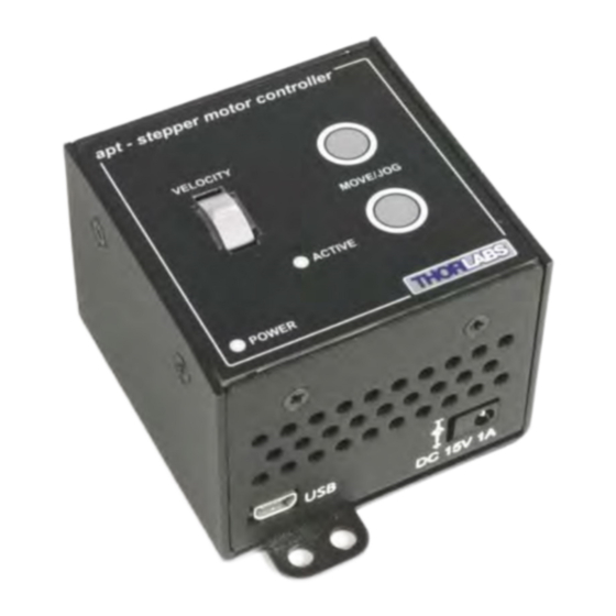
T-Cube Stepper Motor Controller 4.2 Front Panel Controls and Indicators apt - stepper controller VELOCITY MOVE/JOG ACTIVE POWER Fig. 4.1 Front Panel Controls and Indicators MOVE Controls - These controls allow all motor moves to be initiated. Jog Buttons - Used to jog the motors and make discrete position increments in either direction - see Section 5.5. -
Page 20: Button Operation
Chapter 4 4.4 Button Operation The buttons on the front of the unit can be used to control the motor in a number of ways, as described below. 4.4.1 Homing A ‘Home’ move is performed to establish a datum from which subsequent absolute position moves can be measured (see Section 5.3. -
Page 21: Chapter 5 Pc Operation - Tutorial
(such as motor moves) can be initiated. Parameter settings can be saved, which simplifies system set up whenever the software is run up. 1) Run the Kinesis software - Start/All Programs/Thorlabs/Kinesis/Kinesis. 2) Notice how the ZST225(B) actuator type, selected at start up, is displayed in the window. -
Page 22: Homing Motors
Chapter 5 5.3 Homing Motors Homing the motor moves the actuator to the home limit switch and resets the internal position counter to zero. The limit switch provides a fixed datum that can be found after the system has been powered up. Fig. -
Page 23: Changing Motor Parameters And Moving To An Absolute Position
T-Cube Stepper Motor Controller 5.4 Changing Motor Parameters and Moving to an Absolute Position Absolute moves are measured in real world units (e.g. millimetres), relative to the Home position. Moves are performed using a trapezoidal velocity profile (see Appendix D , Section D.1.3.). -
Page 24: Jogging
5.5 Jogging During PC operation, the motor actuators are jogged using the GUI panel arrow keys. There are two jogging modes available, ‘Single Step’ and ‘Continuous’. In ‘Single Step’ mode, the motor moves by the step size specified in the Step Distance parameter. -
Page 25: Setting Move Sequences
T-Cube Stepper Motor Controller 5.6 Setting Move Sequences The Kinesis software allows move sequences to be programmed, allowing several positions to be visited without user intervention. For more details and instructions on setting move sequences, please see the Kinesis Helpfile. 5.7 Changing and Saving Parameter Settings During operation, certain settings (e.g. -
Page 26: Chapter 6 Software Reference
Chapter 6 Chapter 6 Software Reference 6.1 Introduction This chapter gives an explanation of the parameters and settings accessed from the Kinesis software running on a PC. For information on the methods and properties which can be called via a programming interface, see Appendix D 6.2 GUI Panel The following screen shot shows the graphical user interface (GUI) displayed when accessing the Stepper Driver T-Cube using the Kinesis software. - Page 27 T-Cube Stepper Motor Controller Velocity Parameters - the present setting for the move velocity parameters and the jog step size. The travel range of the associated stage/actuator is also displayed. These settings can be adjusted as described previously, or by clicking the Settings button to display the settings window, see Section 6.3.2.
- Page 28 Chapter 6 Home - sends the motor to its 'Home' position - see Appendix D Section D.2.2. Stop - halts the movement of the motor. Lower Display - Shows the present state of the motor, e.g. Idle, Moving, Moving EXT or Homing. Also shows the part number of the associated actuator or stage.
-
Page 29: Settings Panel
T-Cube Stepper Motor Controller 6.3 Settings Panel When the 'Settings' button on the GUI panel is clicked, the 'Settings' window is displayed. This panel allows motor operation parameters such as move/jog velocities, and stage/axis information to be modified. Note that all of these parameters have programmable equivalents (refer to the Kinesis Server helpfile for further details. - Page 30 Chapter 6 6.3.2 Moves/Jogs Tab Fig. 6.2 Stepper Driver T-Cube - Move/Jog Settings Display Units By default, the unit will display position in real world units (mm or degrees). If required, the units can be changed to so that the display shows other positional units (cm, µm, µrad etc).
- Page 31 T-Cube Stepper Motor Controller In ‘Continuous’ mode, the motor actuator will accelerate and move at the jog velocity while the button is held down.. Fig. 6.3 Jog Modes Jog - the motor moves by the distance specified in the Step Size parameter. Continuous - the motor continues to move until the jog signal is removed (i.e.
- Page 32 Chapter 6 Backlash Distance - The system compensates for lead screw backlash during reverse direction moves, by moving passed the demanded position by a specified amount, and then reversing. This ensures that positions are always approached in a forward direction. The Backlash Distance is specified in real world units (millimeters or degrees).
- Page 33 T-Cube Stepper Motor Controller motion profile. The Bow Value is applied in mm/s and is derived from the Bow Index field as follows: (Bow Index -1) Bow Value = 2 within the range 1 to 262144 (Bow Index 1 to 18). In this profile mode, the acceleration increases gradually from 0 to the specified acceleration value, then decreases at the same rate until it reaches 0 again at the specified velocity.
- Page 34 Chapter 6 6.3.3 Calibration Tab Note This section is applicable only to NRT100, NRT150, LTS150, LTS300 and MLJ050 series stages, DRV013 and DRV014 actuators. Fig. 6.6 Stepper Driver T-Cube - Calibration Settings Calibration enables the server to correct for any mechanical errors inherent in the system.
- Page 35 They need to be set accordingly such that a particular stage is driven properly by the system. For Thorlabs stages, the Kinesis software can be used to associate a specific stage and axis type with the motor channel (see Section 3.5. for further details on how to associate a stage and axis).
- Page 36 Chapter 6 Homing Settings When homing, a stage typically moves in the reverse direction, (i.e. towards the reverse limit switch). The following settings allow support for stages with both Forward and Reverse limits. Note Typically, the following two parameters are set the same, i.e. both Forward or both Reverse.
- Page 37 T-Cube Stepper Motor Controller 6.3.5 Advanced Tab Fig. 6.8 Stepper Driver T-Cube - Advanced Settings Potentiometer Settings The potentiometer slider is sprung such that when released it returns to it’s central position. In this central position the motor is stationary. As the slider is moved away from the centre, the motor begins to move.
- Page 38 Chapter 6 The Resting Power is entered as a percentage of full power. Note The default values applied by the software have been selected based on the type of stage or actuator associated with the motor drive. Modify these values with caution (particularly the rest power) as the risk of damage to the motor due to overheating is significant.
- Page 39 T-Cube Stepper Motor Controller Right/Lower Button Pos.: The position to which the motor will move when the bottom button is pressed. Note A ‘Home’ move can be performed by pressing and holding both buttons for 2 seconds. This function is irrespective of the ‘Button Mode’ setting. Drive Array Velocities These parameters relate to the velocity for moves initiated by the DRIVE bar graph.
-
Page 40: Appendix A Rear Panel Connector Pinout Details
Chapter 6 Appendix A Rear Panel Connector Pinout Details A.1 Rear Panel Motor Control Connector The ‘Motor’ connector provides connection to the stepper motor actuator. The pin functions are detailed in Fig. A.1. Description Description Ground CCW Limit Switch CW Limit Switch Enc A +ve Phase B -ve Enc A -ve... -
Page 41: Appendix B Preventive Maintenance
Note The equipment contains no user servicable parts. Only personnel authorized by Thorlabs Ltd and trained in the maintenance of this equipment should remove its covers or attempt any repairs or adjustments. Maintenance is limited to safety testing and cleaning as described in the following sections. -
Page 42: Appendix C Specifications
Appendix C Specifications C.1 Specifications Parameter Value Motor Output Motor Drive Voltage 12-15 V (Depending on Supply) Motor Drive Current 750 m A (peak) Motor Drive Type 12-bit PWM Control Control Algorithm Open Loop Microstepping High ResolutionStepping 2048 Microsteps per Full Step 49,152 Microsteps per Revolution (24 Step Motor)( 409600 Microsteps per Revolution (200 Step Motor) Position Feedback... - Page 43 T-Cube Stepper Motor Controller Recommended Motor Requirements Peak Powers 15 W Step Angle Range 20° to 1.8° Rated Phase Current up to 1 A Peak Motor Mode Current Coil Resistance (nominal) 5 to 20 Ω Coil Inductance (nominal) 2 to 5.5 mH Phases Position Control Open Loop...
-
Page 44: Appendix D Stepper Motor Operation - Background
The size of the microstep depends on the resolution of the driver electronics. When used with the Thorlabs Stepper Driver T-Cube,128 microsteps per full step can be achieved, giving a total resolution of 3072 microsteps per revolution for a 24 full step motor. - Page 45 T-Cube Stepper Motor Controller orientation of the magnetic field generated by the stator and the orientation in which the rotor shaft comes to rest. D.1.2 Positive and Negative Moves Positive and negative are used to describe the direction of a move. A positive move means a move from a smaller absolute position to a larger one, a negative move means the opposite.
- Page 46 Chapter 6 The S-curve profile is a trapezoidal curve with an additional 'Bow Value' parameter, which limits the rate of change of acceleration and smooths out the contours of the motion profile. The Bow Value is specified in mm/s and is derived from the Bow Index field as follows: The Bow Value is applied in mm/s and is derived from the Bow Index field as follows:...
- Page 47 T-Cube Stepper Motor Controller D.2 Positioning a Stage D.2.1 General Whenever a command is received to move a stage, the movement is specified in motion units, (e.g. millimetres). This motion unit value is converted to microsteps before it is sent to the stage by the Kinesis software. Each motor in the system has an associated electronic counter in the controller, which keeps a record of the net number of microsteps moved.
- Page 48 Chapter 6 Home position can be found. Movement is allowed right through the switch position in either direction. Datum switch +ve limit switch -ve limit switch (or stop) Linear stage Rotary stage Fig. D.4 Stage limit switches D.2.4 Minimum and Maximum Positions These positions are dependent upon the stage or actuator to which the motors are fitted, and are defined as the minimum and maximum useful positions of the stage relative to the ‘Home’...
- Page 49 T-Cube Stepper Motor Controller D.2.5 Power Saving The current needed to hold a motor in a fixed position is much smaller than the current needed to move it. When a stepper motor is at rest it is advisable to reduce the phase (holding) currents so that the motor does not overheat.
-
Page 50: Appendix E Regulatory
Chapter 6 Appendix E Regulatory E.1 Declarations Of Conformity E.1.1 For Customers in Europe See Section E.3. E.1.2 For Customers In The USA This equipment has been tested and found to comply with the limits for a Class A digital device, persuant to part 15 of the FCC rules. These limits are designed to provide reasonable protection against harmful interference when the equipment is operated in a commercial environment. - Page 51 • left over parts of units disassembled by the user (PCB's, housings etc.). If you wish to return a unit for waste recovery, please contact Thorlabs or your nearest dealer for further information. E.2.2 Waste treatment on your own responsibility If you do not return an "end of life"...
- Page 52 Chapter 6 E.3 CE Certificate HA0333T Rev BK Sept 2015...
- Page 53 T-Cube Stepper Motor Controller...
- Page 54 Chapter 6 HA0333T Rev BK Sept 2015...
-
Page 55: Appendix F Thorlabs Worldwide Contacts
Thorlabs Worldwide Contacts Appendix F For technical support or sales inquiries, please visit us at www.thorlabs.com/contact for our most up-to-date contact information. USA, Canada, and South America UK and Ireland Thorlabs, Inc. Thorlabs Ltd. sales@thorlabs.com sales.uk@thorlabs.com techsupport@thorlabs.com techsupport.uk@thorlabs.com Europe Scandinavia... - Page 56 www.thorlabs.com...
Need help?
Do you have a question about the TST101 and is the answer not in the manual?
Questions and answers