Table of Contents
Advertisement
Quick Links
Advertisement
Table of Contents

Subscribe to Our Youtube Channel
Related Manuals for THORLABS TST001


Summary of Contents for THORLABS TST001
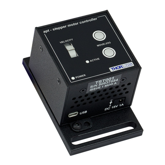
- Page 1 TST001 T-Cube Stepper Motor Controller User Guide Original Instructions...
-
Page 2: Table Of Contents
Contents Chapter 1 Safety ..................... 4 1.1 Safety Information .................. 4 1.2 General Warnings .................. 4 Chapter 2 Overview and Setup ..............5 2.1 Introduction ..................... 5 2.2 T-Cube Controller Hub ................6 2.3 APT PC Software Overview ..............7 2.3.1 Introduction ...................... - Page 3 Appendix A Rear Panel Connector Pinout Details ........54 Appendix B Preventive Maintenance ............55 Appendix C Specifications and Associated Parts ........56 Appendix D Motor Control Method Summary ........... 58 Appendix E Regulatory ................67 Appendix F Thorlabs Worldwide Contacts ..........71...
-
Page 4: Chapter 1 Safety
Chapter 1 Safety 1.1 Safety Information For the continuing safety of the operators of this equipment, and the protection of the equipment itself, the operator should take note of the Warnings, Cautions and Notes throughout this handbook and, where visible, on the product itself. The following safety symbols may be used throughout the handbook and on the equipment itself. -
Page 5: Chapter 2 Overview And Setup
Although targeted at lower power operations this product is fully featured with a highly flexible and powerful DSP controller that provides a unique high resolution microstepping capability for such a compact unit. The TST001 is optimised for 'out of the box' operation with the Thorlabs range of ZST mini stepper motor actuators, however its highly flexible parameter set also supports operation with a wide range of third party stepper motors and associated stages/actuators. -
Page 6: T-Cube Controller Hub
For power, a compact multi-way power supply unit (TPS008) is available from Thorlabs allowing up to 8 T-Cube Drivers to be powered from a single mains outlet. This power supply unit is also designed to take up minimal space and can be mounted to the optical table in close proximity to the driver units, connected via short power leads. -
Page 7: Apt Pc Software Overview
T-Cube Stepper Motor Controller 2.3 APT PC Software Overview 2.3.1 Introduction As a member of the APT range of controllers, the Stepper Driver T-Cube shares many of the associated software benefits. This includes USB connectivity (allowing multiple units to be used together on a single PC), fully featured Graphical User Interface (GUI) panels, and extensive software function libraries for custom application development. -
Page 8: Aptuser Utility
Chapter 2 2.3.2 APTUser Utility The APTUser application allows the user to interact with a number of APT hardware control units connected to the host PC. This program displays multiple graphical instrument panels to allow multiple APT units to be controlled simultaneously. All basic operating parameters can be altered and, similarly, all operations (such as motor moves) can be initiated. -
Page 9: Apt Config Utility
T-Cube Stepper Motor Controller 2.3.3 APT Config Utility There are many system parameters and configuration settings associated with the operation of the APT Server. Most can be directly accessed using the various graphical panels, however there are several system wide settings that can be made 'off-line' before running the APT software. -
Page 10: Apt Server (Activex Controls)
Chapter 2 2.3.4 APT Server (ActiveX Controls) ActiveX Controls are re-usable compiled software components that supply both a graphical user interface and a programmable interface. Many such Controls are available for Windows applications development, providing a large range of re-usable functionality. -
Page 11: Software Upgrades
APT controllers. 2.3.5 Software Upgrades Thorlabs operate a policy of continuous product development and may issue software upgrades as necessary. Detailed instructions on installing upgrades are included on the APT Software... -
Page 12: Chapter 3 Getting Started
If you experience any problems when installing software, contact Thorlabs on +44 (0)1353 654440 and ask for Technical Support. DO NOT CONNECT THE STAGE TO YOUR PC YET 1) Download the software from www.thorlabs.com. -
Page 13: Mechanical Installation
T-Cube Stepper Motor Controller 3.2 Mechanical Installation 3.2.1 Environmental Conditions Warning Operation outside the following environmental limits may adversely affect operator safety. Location Indoor use only Maximum altitude 2000 m Temperature range C to 40 Maximum Humidity Less than 80% RH (non-condensing) at 31°C To ensure reliable operation the unit should not be exposed to corrosive agents or excessive moisture, heat or dust. -
Page 14: Removing The Baseplate
Chapter 3 3.2.3 Removing the Baseplate The baseplate must be removed before the rubber feet (supplied) can be fitted, or the unit is connected to the USB controller hub.. Detail A Detail B Baseplate attachment screws Baseplate removed and rubber feet fitted Fig. -
Page 15: Electrical Installation
Fig. 3.2 Rear Panel Connections The unit is supplied with a 15 pin D-type connector as shown above, which is compatible with all Thorlabs stepper motor actuators (refer to Appendix A details of pin outs). 3.3.2 Using The TCH002 Controller Hub... -
Page 16: Connecting To A Standalone Power Supply
1) Using the front panel connector as shown above, connect the unit to a regulated DC power supply of 15 V, 1A. Thorlabs offers a compact, multi-way power supply unit (TPS008), allowing up to eight Driver T-Cubes to be powered from a single mains outlet. A single way wall plug supply (TPS001) for powering a single Driver T-Cube is also available. -
Page 17: Select The Stage Type (Using Aptconfig)
(e.g. for a custom stage type not selectable using the APT Config utility) - see Section 6.3.2. 1) Shut down all applications using the APT software components (e.g. APT User or your own custom application). 2) Run the APT Config utility - Start/Programs/Thorlabs/APT/APT Config. - Page 18 Chapter 3 3) From the 'APT Configuration Utility' window, click the 'Stage' tab. Fig. 3.4 APT Configuration Utility - Stage Tab 4) In the ‘Motor’ field, select the serial number of the stepper motor controller to be configured (this number can be found on the side of the unit). 5) In the ‘Stage’...
-
Page 19: Verifying Software Operation
T-Cube Stepper Motor Controller 3.6 Verifying Software Operation 3.6.1 Initial Setup The APT Software should be installed (Section 3.1.) and the stage association performed (Section 3.5.) before software operation can be verified. 1) Run the APTUser utility and check that the Graphical User Interface (GUI) panel appears and is active. - Page 20 Chapter 3 Follow the tutorial steps described in Chapter 4 for further verification of operation.’ Note The 'APT Config' utility can be used to set up simulated hardware configurations and place the APT Server into simulator mode. In this way it is possible to create any number and type of simulated (virtual) hardware units in order to emulate a set of real hardware.
-
Page 21: Chapter 4 Standalone Operation
The Stepper Driver T-Cube has been designed specifically to operate with the Thorlabs ZST series of stepper motors, however when used in conjunction with the BOC series breakout cable, it can also drive a variety of lower powered third party motors (15V operation) equipped with or without encoder feedback. -
Page 22: Front Panel Controls And Indicators
Chapter 4 4.2 Front Panel Controls and Indicators apt - stepper controller VELOCITY MOVE/JOG ACTIVE POWER Fig. 4.1 Front Panel Controls and Indicators MOVE Controls - These controls allow all motor moves to be initiated. Jog Buttons - Used to jog the motors and make discrete position increments in either direction - see Section 5.6. -
Page 23: Button Operation
T-Cube Stepper Motor Controller 4.4 Button Operation The buttons on the front of the unit can be used to control the motor in a number of ways, as described below. 4.4.1 Homing A ‘Home’ move is performed to establish a datum from which subsequent absolute position moves can be measured (see Section 5.3. -
Page 24: Increasing The Maximum Speed
Modify these values with caution as the risk of damage to the motor due to overheating is significant. For the Thorlabs ZST series actuators, the moving phase power is set to 60% at the factory. This is appropriate for velocities of 0 to 250 µm/s. -
Page 25: Chapter 5 Pc Operation - Tutorial
(such as motor moves) can be initiated. Hardware configurations and parameter settings can be saved, which simplifies system set up whenever APT User is run up. Fig. 5.1 Typical APT User Screen 1) Run the APT User program - Start/Programs/Thorlabs/APT/APT User. - Page 26 Chapter 5 2) Notice how the ZST12(B) actuator type, selected in Section 3.5. is displayed in the ‘Settings’ window. See Section 5.11. and Section 6.3. for further details on the parameter values shown in the ‘Settings’ display. Fig. 5.2 Stepper Driver T-Cube Software GUI The APT User utility will be used throughout the rest of this tutorial to interface with the Stepper Driver T-Cube.
-
Page 27: Homing Motors
T-Cube Stepper Motor Controller 5.3 Homing Motors Homing the motor moves the actuator to the home limit switch and resets the internal position counter to zero. The limit switch provides a fixed datum that can be found after the system has been powered up. Fig. -
Page 28: Moving To An Absolute Position
Chapter 5 5.4 Moving to an Absolute Position Absolute moves are measured in real world units (e.g. millimetres), relative to the Home position. 1) Click the position display. Fig. 5.4 Absolute Position Popup Window 2) Enter 3.0 into the pop up window 3) Click ‘OK’. -
Page 29: Changing Motor Parameters
T-Cube Stepper Motor Controller 5.5 Changing Motor Parameters Moves are performed using a trapezoidal velocity profile (see Appendix E , Section E.1.3.). The velocity settings relate to the maximum velocities at which a move is performed, and the acceleration at which the motor speeds up from zero to maximum velocity. -
Page 30: Jogging
Chapter 5 5.6 Jogging During PC operation, the motor actuators are jogged using the GUI panel arrow keys. There are two jogging modes available, ‘Single Step’ and ‘Continuous’. In ‘Single Step’ mode, the motor moves by the step size specified in the Step Distance parameter. -
Page 31: Graphical Control Of Motor Positions (Point And Move)
T-Cube Stepper Motor Controller 5.7 Graphical Control Of Motor Positions (Point and Move) The GUI panel display can be changed to a graphical display, showing the position of the motor channel(s). Moves to absolute positions can then be initiated by positioning the mouse within the display and clicking. - Page 32 Chapter 5 Move Mode When ‘Move’ is selected, the motors move to an absolute position which corresponds to the position of the cursor within the screen. To specify a move: 1) Position the mouse within the window. For reference, the absolute motor position values associated with the mouse position is displayed in the 'Cursor Position field.
-
Page 33: Setting Move Sequences
T-Cube Stepper Motor Controller 5.8 Setting Move Sequences This section explains how to set move sequences, allowing several positions to be visited without user intervention. For details on moving to absolute positions initiated by a mouse click – see Section 5.7. - Page 34 Chapter 5 3) Select 'New' to display the 'Move Editor' panel. Fig. 5.10 Move Editor Window Move data is entered/displayed as follows: Dist/Pos: - the distance to move from the current position (if 'Relative' is selected) or the position to move to (if 'Absolute' is selected). Dwell Time: - after the move is performed, the system can be set to wait for a specified time before performing the next move in the sequence.
- Page 35 T-Cube Stepper Motor Controller 5) Enter the required move data into the Move Editor and click OK. The move data is displayed in the main window as shown below. Fig. 5.11 Main Window with Move Data 6) Repeat step 4 as necessary to build a sequence of moves. Move data can be copied, deleted, cut/pasted and edited by right clicking the data line(s) and selecting the appropriate option in the pop up menu (shown below).
-
Page 36: Creating/Loading A Settings File
Chapter 5 5.9 Creating/Loading a Settings File 5.9.1 Introduction APTUser can be used either to control the physical hardware connected via the USB bus, or to interact with a simulated hardware configuration set up using the APTConfig utility (see Section 5.10.). Normally, when the APTServer is run up, the default settings (e.g. - Page 37 T-Cube Stepper Motor Controller 3) Click 'OK'. The GUI panel(s) for the selected unit is added to the display. 4) Repeat items (1) to (3) as necessary until all required APT unit GUI panels are displayed.. 5) Adjust the settings as necessary, using the 'Settings' button on each GUI panel. 6) From the 'File' menu, select 'Save'.
- Page 38 Chapter 5 5.9.3 Automatically Loading a Settings Group on Start Up 1) From the 'Tools' menu, select 'Options'. The Options window is displayed. 2) Select the 'Automatically load settings on Startup' box, then click 'OK'. 3) On boot up, the system will now load the most recently used settings group. Warning Settings should only be loaded automatically when the same hardware set up is being used for prolonged periods of time.
-
Page 39: Creating A Simulated Configuration Using Apt Config
To create a simulated configuration proceed as follows: 1) Run the APT Config utility - Start/All Programs/Thorlabs/APT/APT Config. 2) Click the 'Simulator Configuration' tab. Fig. 5.14 APT Configuration Utility - Simulator Configuration Tab... - Page 40 4) In the 'Simulator' field, check the ‘Enable Simulator Mode’ box. The name of the most recently used configuration file is displayed in the 'Current Configuration' window. 5) In the ‘Control Unit’ field, select ‘1 Ch Stepper Driver T-Cube (TST001)’. HA0141T Rev 7 Oct 2014...
- Page 41 T-Cube Stepper Motor Controller 6) In the ‘Enter 6 digit serial number’ field, enter the serial number of your OptoST unit. Note Each physical APT hardware unit is factory programmed with a unique 8 digit serial number. In order to simulate a set of ‘real’ hardware the Config utility allows an 8 digit serial number to be associated with each simulated unit.
-
Page 42: Stage/Axis Tab
APTUser. These parameters should not be altered for pre-defined Thorlabs stages and actuators selected using APT Config, as it may adversely affect the performance of the stage. -
Page 43: Chapter 6 Software Reference
Chapter 6 Software Reference 6.1 Introduction This chapter gives an explanation of the parameters and settings accessed from the APT software running on a PC. For information on the methods and properties which can be called via a programming interface, see Appendix D 6.2 GUI Panel The following screen shot shows the graphical user interface (GUI) displayed when accessing the Stepper Driver T-Cube using the APTUser utility. - Page 44 Chapter 6 Travel - displays the range of travel (in millimeters or degrees) of the motor. Moving - lit when the motor is in motion. Enable - applies power to the motor. With the motor enabled, the LED in the button is lit.
-
Page 45: Settings Panel
T-Cube Stepper Motor Controller 6.3 Settings Panel When the 'Settings' button on the GUI panel is clicked, the 'Settings' window is displayed. This panel allows motor operation parameters such as move/jog velocities, and stage/axis information to be modified. Note that all of these parameters have programmable equivalents accessible through the ActiveX methods and properties on this Control (refer to the Programming Guide in the APTServer helpfile for further details and to Section 2.3.4. - Page 46 Chapter 6 Jogs Jogs are initiated by using the ‘Jog’ keys on the GUI panel (see Section 5.6.), or the Jog Buttons on the front panel of the unit. Velocity Profile (specified in real world units, millimetres or degrees) MinVel - In current versions of software the ‘Min Vel’ parameter is locked at zero and cannot be adjusted.
- Page 47 T-Cube Stepper Motor Controller Profiled - the motor stops in a profiled manner using the jog Velocity Profile parameters set above. Step Distance - The distance to move when a jog command is initiated. The step size is specified in real world units (mm or degrees dependent upon the stage). Backlash Correction - The system compensates for lead screw backlash during reverse direction moves, by moving passed the demanded position by a specified amount, and then reversing.
-
Page 48: Stage/Axis Tab
For Thorlabs stages, the APT Config utility can be used to associate a specific stage and axis type with the motor channel (refer to the APT Config helpfile for further details on how to associate a stage and axis). - Page 49 T-Cube Stepper Motor Controller Min Pos - the stage/actuator minimum position (typically zero). Max Pos - the stage/actuator maximum position. Pitch - the pitch of the motor lead screw (i.e. the distance travelled (in mm or degrees) per revolution of the leadscrew). Units - the ‘real world’...
- Page 50 ‘Steps Per Rev’ parameter is entered as full steps, not microsteps. The system automatically applies a factor of 128 microsteps per full step. The stepper motors used on the majority of Thorlabs stages/actuators have 200 full steps per rev and no gearbox fitted. For these motors the Steps Per Rev and Gearbox Ratio parameters have values of 200 and 1 respectively.
-
Page 51: Advanced Tab
Modify these values with caution as the risk of damage to the motor due to overheating is significant. For the Thorlabs ZST series actuators, the moving phase power is set to 60% at the factory. This is appropriate for velocities of 0 to 250 µm/s. - Page 52 Chapter 6 currents so that the motor does not overheat. When moving, these phase currents are boosted to provide sufficient motor torque and minimise the possibility of stalling (missed steps). The values are entered as a percentage of full power. Indicator LED Modes The ‘Active’...
- Page 53 T-Cube Stepper Motor Controller Note The following parameters are applicable only if ‘Go to Position is selected in the ‘Button Mode’ field. Left/Top Button Pos.: The position to which the motor will move when the top button is pressed. Right/Bottom Button Pos.: The position to which the motor will move when the bottom button is pressed.
-
Page 54: Appendix A Rear Panel Connector Pinout Details
Appendix A Rear Panel Connector Pinout Details A.1 Rear Panel Motor Control Connector The ‘Motor’ connector provides connection to the stepper motor actuator. The pin functions are detailed in Fig. A.1. Description Description Ground For Future Use CCW Limit Switch CW Limit Switch Enc A +ve Phase B -ve... -
Page 55: Appendix B Preventive Maintenance
The equipment contains no user servicable parts. There is a risk of severe electrical shock if the equipment is operated with the covers removed. Only personnel authorized by Thorlabs Ltd and trained in the maintenance of this equipment should remove its covers or attempt any repairs or adjustments. -
Page 56: Appendix C Specifications And Associated Parts
Appendix C Specifications and Associated Parts C.1 Specifications Parameter Value Motor Output Motor Drive Voltage 12-15 V (Depending on Supply) Motor Drive Current 500 mA (peak) Motor Drive Type 10-bit Sign/Magnitude PWM Control Algorithm Open Loop Microstepping (Closed Loop using PC) High ResolutionStepping 128 Microsteps per Full Step 3072 Microsteps per Revolution (... - Page 57 T-Cube Stepper Motor Controller Recommended Motor Requirements Peak Powers Step Angle Range 20° to 1.8° Rated Phase Current 10 mA to 250 mA Motor Mode Current 5 to 20 Ω¶ Coil Resistance (nominal) Coil Inductance (nominal) 2 to 5.5 mH Phases Position Control Open Loop...
-
Page 58: Appendix D Motor Control Method Summary
Appendix D Motor Control Method Summary The 'Motor' ActiveX Control provides the functionality required for a client application to control one or more of the APT series of motor controller units. To specify the particular controller being addressed, every unit is factory programmed with a unique 8-digit serial number. - Page 59 T-Cube Stepper Motor Controller GetHWLimSwitches Gets the limit switch configuration settings. GetJogMode Gets the jogging button operating modes. GetJogMode_Mode Get the jogging button operating mode (returned by value). GetJogMode_StopMode Gets the jogging button stopping mode (returned by value). GetJogStepSize Gets the jogging step size. GetJogStepSize_StepSize Gets the jogging step size (returned by value).
- Page 60 Appendix D Identify Identifies the controller by flashing unit LEDs. LLGetStatusBits Gets the controller status bits encoded in 32 bit integer. LoadParamSet Loads stored settings for specific controller. MoveAbsolute Initiates an absolute move. MoveAbsoluteEnc Initiates an absolute move with specified positions for encoder equipped stages.
- Page 61 T-Cube Stepper Motor Controller StopCtrl Stops the ActiveX Control (stops communication with controller) StopImmediate Stops a motor move immediately. StopProfiled Stops a motor move in a profiled (decelleration) manner. Properties APTHelp Specifies the help file that will be accessed when the user presses the F1 key.
- Page 62 The size of the microstep depends on the resolution of the driver electronics. When used with the Thorlabs Stepper Driver T-Cube,128 microsteps per full step can be achieved, giving a total resolution of 3072 microsteps per revolution for a 24 full step motor.
- Page 63 T-Cube Stepper Motor Controller E.1.2 Positive and Negative Moves Positive and negative are used to describe the direction of a move. A positive move means a move from a smaller absolute position to a larger one, a negative move means the opposite. In the case of a linear actuator, a positive move takes the platform of the stage further away from the motor.
- Page 64 Appendix E E.2.2 Home position When the system is powered up, the position counters in the controller are all set to zero and consequently, the system has no way of knowing the position of the stage in relation to any physical datum. A datum can be established by sending all the motors to their ‘Home’...
- Page 65 T-Cube Stepper Motor Controller E.2.4 Minimum and Maximum Positions These positions are dependent upon the stage or actuator to which the motors are fitted, and are defined as the minimum and maximum useful positions of the stage relative to the ‘Home’ position - see Fig. E.4. The distance from the Minimum position to the Maximum position is the ‘useful travel’...
- Page 66 Appendix E E.3 Error Correction E.3.1 Backlash correction The term backlash refers to the tendency of the stage to reach a different position depending on the direction of approach. Backlash can be overcome by always making the last portion of a move in the same direction, conventionally the positive direction.
-
Page 67: Appendix E Regulatory
Appendix F Regulatory F.1 Declarations Of Conformity F.1.1 For Customers in Europe This equipment has been tested and found to comply with the EC Directives 89/336/EEC ‘EMC Directive’ and 73/23/EEC ‘Low Voltage Directive’ as amended by 93/68/EEC. Compliance was demonstrated by conformance to the following specifications which have been listed in the Official Journal of the European Communities: Safety EN61010: 2001 Installation Category II, Polution Degree II. - Page 68 • left over parts of units disassembled by the user (PCB's, housings etc.). If you wish to return a unit for waste recovery, please contact Thorlabs or your nearest dealer for further information. HA0141T Rev 7 Oct 2014...
- Page 69 T-Cube Stepper Motor Controller F.2.2 Waste treatment on your own responsibility If you do not return an "end of life" unit to the company, you must hand it to a company specialized in waste recovery. Do not dispose of the unit in a litter bin or at a public waste disposal site.
- Page 70 Chapter 6 HA0141T Rev 7 Oct 2014...
-
Page 71: Appendix F Thorlabs Worldwide Contacts
UK and Ireland Thorlabs, Inc. Thorlabs Ltd. sales@thorlabs.com sales.uk@thorlabs.com techsupport@thorlabs.com techsupport.uk@thorlabs.com Europe Scandinavia Thorlabs GmbH Thorlabs Sweden AB europe@thorlabs.com scandinavia@thorlabs.com France Brazil Thorlabs SAS Thorlabs Vendas de Fotônicos Ltda. sales.fr@thorlabs.com brasil@thorlabs.com Japan China Thorlabs Japan, Inc. Thorlabs China sales@thorlabs.jp chinasales@thorlabs.com... - Page 72 www.thorlabs.com...
Need help?
Do you have a question about the TST001 and is the answer not in the manual?
Questions and answers