Table of Contents
Advertisement
Quick Links
Advertisement
Table of Contents

Related Manuals for THORLABS SA201


Summary of Contents for THORLABS SA201
- Page 1 SA201, SA201-EC Spectrum Analyzer Controller Operating Manual...
-
Page 2: Table Of Contents
3.1. PD Blanking Circuit ............10 3.2. Replacing the Fuse ............11 1.1.3. Cleaning..................12 Chapter 4 Recommended Setup ............. 13 Chapter 5 Specifications ..............14 Chapter 2 Regulatory ............... 17 Chapter 3 Thorlabs Worldwide Contacts........18 Page 1 Rev D, February 26, 2013... - Page 3 SA201, SA201-EC Chapter 1: Overview Table of Figures Figure 1: SA201 Front Panel Controls ............... 5 Figure 2: Trigger Logic ..................7 Figure 3: Saw tooth Waveform (left), Triangle Waveform (right) ......7 Figure 4: SA201 Rear Panel Connections ............8 Figure 5: Recommended Setup Diagram ............
-
Page 4: Overview
1.1.1. Parts List Below is a list of all components shipped with the SA201 Spectrum Analyzer Controller. • SA201 Spectrum Analyzer Controller •... -
Page 5: Chapter 2 Description
SA201, SA201-EC Chapter 1: Overview Item # Description Item# Description SA200-3B 350-535 nm, 1.5 GHz FSR SA210-3B 350-535 nm, 10 GHz FSR SA200-5B 535-820 nm, 1.5 GHz FSR SA210-5A 525-650 nm, 10 GHz FSR SA200-7A 780 - 930 nm, 1.5 GHz FSR... -
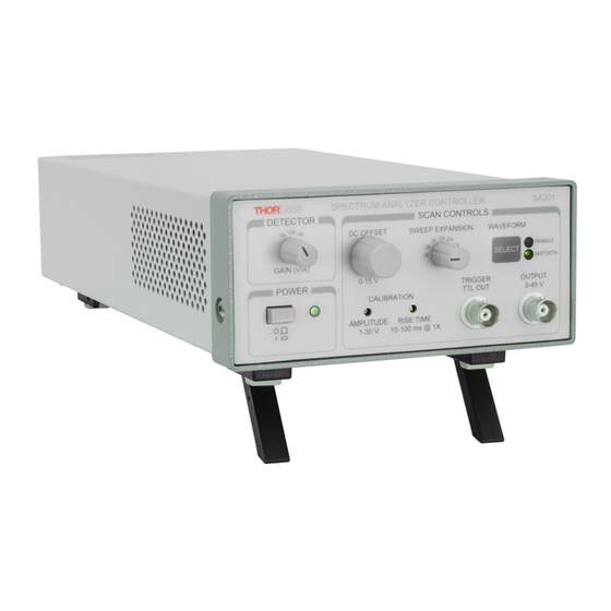
Page 6: Figure 1 Sa201 Front Panel Controls
Figure 1 SA201 Front Panel Controls Detector Gain Adjustment The SA201 includes a built in photodiode amplifier circuit. This amplifier is designed specifically to operate with the detector provided with the SA200 series Fabry Perot Interferometer, allowing the user to monitor the transmission of the cavity. - Page 7 The SA201 allows the user to select between a saw-tooth and triangular waveform. The saw-tooth waveform is desirable for most applications; however the triangle waveform is useful for cavity alignment. The SA201 will default to the saw-tooth waveform during the system power-up. To change the waveform, simply press the ‘WAVEFORM SEL’...
-
Page 8: Figure 2 Trigger Logic
0.6 µF piezo loads at a ramp rate of 1 ms over the full voltage range. The output current is internally limited to prevent damage to the output drive. Note: the output performance specifications assume a Thorlabs Fabry Perot Interferometer module is connected. -
Page 9: Figure 4 Sa201 Rear Panel Connections
This input BNC is used to interface the photodetector, provided with the SA200 scanning heads, to the amplifier circuit. The photodiode amplifier is configured to operate with the Thorlabs supplied photo detectors; however it is possible to operate user supplied photo detectors. To do so, the BNC center contact must be connected to the photo detector cathode and the BNC shell must be connected to the photodiode anode (unbiased operation). - Page 10 Spectrum Analyzer Controller results, a 50 Ω load resistor is recommended at the oscilloscope. Note, the amplifier gain will be halved with a 50 Ω load connected. Voltage Selector Switch The voltage selector switch allows the user to select the input line voltage. The factory default setting is 100/115 VAC as shown in figure 4.
-
Page 11: Chapter 3 Operation
This feature may be disabled as described below: IMPORTANT Disconnect the scanning head or any piezo device from the SA201 output. Disconnect the power cord. Do not open the unit if the power cord is connected. -
Page 12: Replacing The Fuse
125 mA Type ’T’ Slow Blow Fuse – The 125 mA fuse is required for 230 V operation only. Thorlabs supplies a 125 mA fuse with all of its SA201 units and must be installed when operating at 230 VAC. -
Page 13: Cleaning
Switch to the appropriate line voltage. Install the appropriate line cord. 1.1.3. Cleaning The SA201 should only be cleaned with a soft cloth and a mild soap detergent or isopropyl alcohol. Do not use a solvent-based cleaner. 6679-D02 Page 12... -
Page 14: Chapter 4 Recommended Setup
Spectrum Analyzer Controller Chapter 4 Recommended Setup OSCILLOSCOPE CHANNEL 1 CHANNEL 2 TRIGGER PD AMPLIFIER INPUT OUTPUT VOLTAGE SELECT SA201 REAR PANEL SPECTRUM ANALYZER CONTROLER DETECTOR SCAN CONTROLS SELECT GAIN POWER TRIGGER OUTPUT CALIBRATION AMPLITUDE RISETIME SA201 FRONT PANEL Figure 5 Recommended Setup Diagram... -
Page 15: Chapter 5 Specifications
SA201, SA201-EC Chapter 5: Specifications Chapter 5 Specifications Output Characteristics Item # SA201 Waveforms Saw tooth / Triangle Default Waveform Saw tooth Saw tooth Fall Time 1 ms Typical Output Voltage Range 1 to 45 V (offset + amplitude) Max Supply Current... - Page 16 Spectrum Analyzer Controller Photodiode Amplifier Characteristics Item # SA201 Gain Steps 0, 10, 20 dB Transimpedance Gain (Hi-Z) 10K, 100K, 1M V/A Transimpedance Gain (50Ω) 5K, 50K, 500K V/A Gain Error ±0.1% @ 10K (±0.12%) ±0.12% @ 100K (±0.15%) ±0.14% @ 1M (±0.3%) Output Impedance 50 Ω...
- Page 17 SA201, SA201-EC Chapter 5: Specifications Power Supply Item # SA201 Supply Type Linear Voltage Selection Switch Selectable Between 115/230 VAC Input Voltage 100/115/230 VAC Line Frequency 50 – 60 Hz Input Power 15 W Max Fuse Ratings 250 mA @ 100/115 VAC, 125 mA @ 230 Fuse Type Slow Blow Type ‘T’...
-
Page 18: Chapter 2 Regulatory
2.1. Waste Treatment is Your Own Responsibility If you do not return an “end of life” unit to Thorlabs, you must hand it to a company specialized in waste recovery. Do not dispose of the unit in a litter bin or at a public waste disposal site. -
Page 19: Chapter 3 Thorlabs Worldwide Contacts
SA201, SA201-EC Chapter 3: Thorlabs Worldwide Contacts Chapter 3 Thorlabs Worldwide Contacts USA, Canada, and South America UK and Ireland Thorlabs, Inc. Thorlabs Ltd. 56 Sparta Avenue 1 Saint Thomas Place, Ely Newton, NJ 07860 Cambridgeshire CB7 4EX Great Britain... - Page 20 www.thorlabs.com...
Need help?
Do you have a question about the SA201 and is the answer not in the manual?
Questions and answers