Table of Contents
Advertisement
Quick Links
Advertisement
Table of Contents

Related Manuals for THORLABS MLC8 Series


Summary of Contents for THORLABS MLC8 Series
- Page 1 Artisan Technology Group is your source for quality new and certified-used/pre-owned equipment SERVICE CENTER REPAIRS WE BUY USED EQUIPMENT • FAST SHIPPING AND DELIVERY Experienced engineers and technicians on staff Sell your excess, underutilized, and idle used equipment at our full-service, in-house repair center We also offer credit for buy-backs and trade-ins •...
- Page 2 Operation Manual Thorlabs Blueline™ Series PRO8000 (-4) / PRO800 Multi laser controller module MLC8xxx 2004 Artisan Technology Group - Quality Instrumentation ... Guaranteed | (888) 88-SOURCE | www.artisantg.com...
- Page 3 Version: 2.10 Date: 22.01.2004 © Copyright 2004, Thorlabs GmbH Artisan Technology Group - Quality Instrumentation ... Guaranteed | (888) 88-SOURCE | www.artisantg.com...
-
Page 4: Table Of Contents
Contents Page General description of the multi LD-controller MLC8xxx 1.1 Safety 1.2 Warranty 1.3 Features 1.3.1 Safety measures for the laser diode 1.3.2 General functions 1.4 Technical data 1.4.1 MLC8025-8 1.4.2 MLC8050-8 1.4.3 MLC8100-8 1.4.4 MLC8200-8 1.5 Operating elements at the front of the module 1.6 Pre-settings 1.6.1 Setting hardware limit I... - Page 5 2.2.4 Selecting constant current or constant power mode 2.2.5 Selecting a TEC module for temperature protection 2.2.6 Activating the temperature protection 2.3 Switching on and off 2.4 Error messages Communicating with a control computer 3.1 General notes on remote control 3.1.1 Nomenclature 3.1.2...
- Page 6 5.3 Certifications and compliances 5.4 Addresses Artisan Technology Group - Quality Instrumentation ... Guaranteed | (888) 88-SOURCE | www.artisantg.com...
- Page 7 We and our international partners are looking forward to hearing from you. In the displays shown by the PRO8 you may find the name PROFILE. PROFILE was the name of the manufacturer before it was acquired by Thorlabs and renamed to Thorlabs GmbH.
-
Page 8: General Description Of The Multi Ld-Controller Mlc8Xxx
PRO8000, PRO8000-4 or PRO800. All modules must only be operated with duly shielded connection cables. Only with written consent from Thorlabs may changes to single components be carried out or components not supplied by Thorlabs be used. This precision device is only dispatchable if duly packed into the complete original packaging including the plastic form parts. - Page 9 1.1 Safety Attention Semiconductor laser modules can deliver up to several 100mW of (maybe) invisible laser radiation! When operated incorrectly, this can cause severe damage to your eyes and health! Be sure to pay strict attention to the safety recommendations of the appropriate laser safety class! This laser safety class is marked on your PRO8000 (-4) / PRO800 plug-in module or on your external laser source used.
-
Page 10: Warranty
1.2 Warranty 1.2 Warranty Thorlabs GmbH warrants material and production of the MLC8xxx modules for a period of 24 months starting with the date of shipment. During this warranty period Thorlabs GmbH will see to defaults by repair or by exchange if these are entitled to warranty. -
Page 11: Features
1.3 Features 1.3 Features 1.3.1 Safety measures for the laser diode To protect the connected laser diodes the MLC8xxx modules contain the following protection circuits: • Softstart when switching on the laser diode current Protection against capacitive and inductive parasitic elements (switching peaks). •... - Page 12 • Key-operated power switch Protection against unauthorized or accidental use. • LabVIEW®- and LabWindows/CVI®-driver ® For the PRO8000 (-4) / PRO800 Thorlabs supplies LabVIEW - and LabWin- ® dows/CVI -drivers for MS Windows 32.
-
Page 13: General Functions
1.3 Features 1.3.2 General functions The current modules MLC8xxx are unipolar current sources for laser diodes. They can be ordered for laser diodes with anode grounded or cathode grounded. The MLC offers two current ranges. The different module types operate the same way, they only differ in maximum current, resolution and accuracy. -
Page 14: Technical Data
1.4 Technical data 1.4 Technical data 1.4.1 MLC8025-8AG/CG Selectable range HIGH Current ranges 5 mA 25 mA Setting accuracy ± 15 µA ± 75 µA Setting- / measurement resolution 1.2 µA 6 µA Noise without ripple (10Hz...10MHz) < 0.5 µA <... -
Page 15: Mlc8100-8
1.4 Technical data 1.4.3 MLC8100-8AG/CG Selectable range HIGH Current ranges 25 mA 100 mA Setting accuracy ± 75 µA ± 300 µA Setting- / measurement resolution 6 µA 25 µA Noise without ripple (10Hz...10MHz) < 0.5 µA < 1 µA Ripple (50Hz, rms) <... -
Page 16: Operating Elements At The Front Of The Module
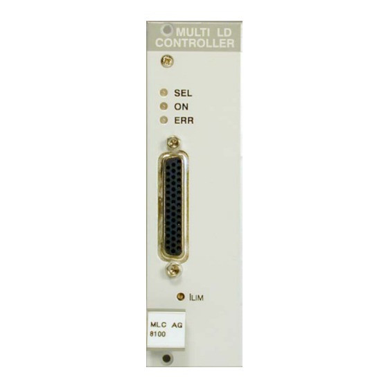
1.5 Operating elements at the front of the module 1.5 Operating elements at the front of the module Connector for the laser diodes Potentiometer for I Figure 1 Operating elements on front panel. MLC8xxx / page 9 Artisan Technology Group - Quality Instrumentation ... Guaranteed | (888) 88-SOURCE | www.artisantg.com... -
Page 17: Pre-Settings
1.6 Pre-settings 1.6 Pre-settings 1.6.1 Setting hardware limit I To protect the laser diode the maximum possible current can be limited by hardware setting. The setting affects all outputs simultaneously. The hardware limit I is set with the potentiometer marked I at the front panel of the module. -
Page 18: Connecting Components (Anode Ground Version)
1.7 Connecting components (AG, Anode Ground Version) 1.7 Connecting components (AG, Anode Ground Version) 1.7.1 Pinning of the output connector Figure 2 Pinning of the MLC8xxx output connector (44-pole female HD-SUB) MLC8xxx / page 11 Artisan Technology Group - Quality Instrumentation ... Guaranteed | (888) 88-SOURCE | www.artisantg.com... -
Page 19: Pin Assignment Mlc8Xxx
1.7 Connecting components (AG, Anode Ground Version) 1.7.2 Pin assignment MLC8xxx Each laser is connected to an output channel as shown: output circuit of the MLC Laser and photo diode (n = 1 ... 8) Figure 3 Principle connections for every laser We recommend to use separate lines drilled in pairs (twisted pair) in a common shield for laser diode current and monitor diode current respectively. - Page 20 1.7 Connecting components (AG, Anode Ground Version) 1.7.2.1 Pin assignment sorted by Function Connector LD1C cathode of laser # 1 LD2C cathode of laser # 2 LD3C cathode of laser # 3 LD4C cathode of laser # 4 LD5C cathode of laser # 5 LD6C cathode of laser # 6 LD7C cathode of laser # 7 LD8C cathode of laser # 8...
- Page 21 1.7 Connecting components (AG, Anode Ground Version) GND ground LEDA out for a LED to show the on/off status Interlock to be shortened to any GND pin + 5V - 5V MLC8xxx / page 14 Artisan Technology Group - Quality Instrumentation ... Guaranteed | (888) 88-SOURCE | www.artisantg.com...
- Page 22 1.7 Connecting components (AG, Anode Ground Version) 1.7.2.2 Pin assignment sorted by pin number Connector + 5V - 5V LD8C cathode of laser # 8 PD7A anode photo diode # 7 LD7C cathode of laser # 7 LD6C cathode of laser # 6 PD5A anode photo diode # 5 LD5C cathode of laser # 5 LD4C cathode of laser # 4...
- Page 23 1.7 Connecting components (AG, Anode Ground Version) PD3C cathode photo diode # 3 PD2C cathode photo diode # 2 PD2A anode photo diode # 2 PD1C cathode photo diode # 1 LEDA out for a LED to show the on/off status MLC8xxx / page 16 Artisan Technology Group - Quality Instrumentation ...
-
Page 24: Connecting Laser- And Monitor Diode
1.7 Connecting components (AG, Anode Ground Version) 1.7.3 Connecting laser- and monitor diode Laser diodes are produced in many different housings. Normally the following components are installed together in the chassis of the laser: • Laser diode • Monitor diode •... -
Page 25: Standard Configurations, No Bias Voltage
1.7 Connecting components (AG, Anode Ground Version) 1.7.4 Standard configurations, no bias voltage 1.7.4.1 Laser anode on ground / photo diode cathode on ground n = number of channel (1 to 8) Figure 4 Laser AG / photo diode CG, no bias 1.7.4.2 Laser anode on ground / photo diode anode on ground n = number of channel (1 to 8) Figure 5... -
Page 26: Standard Configurations With Bias Voltage 5V
1.7 Connecting components (AG, Anode Ground Version) 1.7.4.3 Laser anode on ground / photo diode floating n = number of channel (1 to 8) Figure 6 Laser AG / photo diode floating, no bias a bridge (dashed line) may be used either at the laser or at the connector 1.7.5 Standard configurations with bias voltage 5V 1.7.5.1 Laser anode on ground / photo diode cathode on ground n = number of channel (1 to 8) - Page 27 1.7 Connecting components (AG, Anode Ground Version) 1.7.5.2 Laser anode on ground / photo diode anode on ground n = number of channel (1 to 8) Figure 8 Laser AG / photo diode AG, 5V bias 1.7.5.3 Laser anode on ground / photo diode floating n = number of channel (1 to 8) Figure 9 Laser AG / photo diode floating, 5V bias...
-
Page 28: Connecting Interlock And Status Display
1.7 Connecting components (AG, Anode Ground Version) 1.7.6 Connecting interlock and status display Interlock, cable damage monitoring Pin 15 connected to any GND pin of the connector jack will serve as test connector to determine whether the current output for the laser diode may be switched on. Between the two pins a low resistive (<... -
Page 29: Connecting Components (Cathode Ground Version)
1.8 Connecting components (CG, Cathode Ground Version) 1.8 Connecting components (CG, Cathode Ground Version) 1.8.1 Pinning of the output connector Figure 10 Pinning of the MLC8xxx output connector (44-pole female HD-SUB-D) MLC8xxx / page 22 Artisan Technology Group - Quality Instrumentation ... Guaranteed | (888) 88-SOURCE | www.artisantg.com... -
Page 30: Pin Assignment Mlc8Xxx
1.8 Connecting components (CG, Cathode Ground Version) 1.8.2 Pin assignment MLC8xxx Each laser is connected to an output channel as shown: output circuit of the MLC Laser and photo diode (n = 1 ... 8) Figure 11 Principle connections for every laser We recommend to use separate lines drilled in pairs (twisted pair) in a common shield for laser diode current and monitor diode current respectively. - Page 31 1.8 Connecting components (CG, Cathode Ground Version) 1.8.2.1 Pin assignment sorted by Function Connector LD1A anode of laser # 1 LD2A anode of laser # 2 LD3A anode of laser # 3 LD4A anode of laser # 4 LD5A anode of laser # 5 LD6A anode of laser # 6 LD7A anode of laser # 7 LD8A anode of laser # 8...
- Page 32 1.8 Connecting components (CG, Cathode Ground Version) GND ground LEDA out for a LED to show the on/off status Interlock to be shortened to any GND pin + 5V - 5V MLC8xxx / page 25 Artisan Technology Group - Quality Instrumentation ... Guaranteed | (888) 88-SOURCE | www.artisantg.com...
- Page 33 1.8 Connecting components (CG, Cathode Ground Version) 1.8.2.2 Pin assignment sorted by number of pin Connector + 5V - 5V LD8A anode laser # 8 PD7A anode photo diode # 7 LD7A anode laser # 7 LD6A anode laser # 6 PD5A anode photo diode # 5 LD5A anode laser # 5 LD4A anode laser # 4...
- Page 34 1.8 Connecting components (CG, Cathode Ground Version) PD3C cathode photo diode # 3 PD2C cathode photo diode # 2 PD2A anode photo diode # 2 PD1C cathode photo diode # 1 LEDA out for a LED to show the on/off status MLC8xxx / page 27 Artisan Technology Group - Quality Instrumentation ...
-
Page 35: Connecting Laser- And Monitor Diode
1.8 Connecting components (CG, Cathode Ground Version) 1.8.3 Connecting laser- and monitor diode Laser diodes are produced in many different housings. Normally the following components are installed together in the chassis of the laser: • Laser diode • Monitor diode •... -
Page 36: Standard Configurations Without Bias Voltage
1.8 Connecting components (CG, Cathode Ground Version) 1.8.4 Standard configurations without bias voltage 1.8.4.1 Laser cathode on ground / photo diode cathode on ground n = number of channel (1 to 8) Figure 12 Laser CG / photo diode CG, no bias 1.8.4.2 Laser cathode on ground / photo diode anode on ground n = number of channel (1 to 8) Figure 13... - Page 37 1.8 Connecting components (CG, Cathode Ground Version) 1.8.4.3 Laser cathode on ground / photo diode floating n = number of channel (1 to 8) Figure 14 Laser CG / photo diode floating, no bias a connection (dashed line) may be done either at the laser or at the connector MLC8xxx / page 30 Artisan Technology Group - Quality Instrumentation ...
-
Page 38: Standard Configurations With Bias Voltage 5V
1.8 Connecting components (CG, Cathode Ground Version) 1.8.5 Standard configurations with bias voltage 5V 1.8.5.1 Laser cathode on ground / photo diode cathode on ground n = number of channel (1 to 8) Figure 15 Laser CG / photo diode CG, with 5 V bias 1.8.5.2 Laser cathode on ground / photo diode anode on ground n = number of channel (1 to 8) Figure 16... -
Page 39: Connecting Interlock And Status Display
1.8 Connecting components (CG, Cathode Ground Version) 1.8.5.3 Laser cathode on ground / photo diode floating n = number of channel (1 to 8) Figure 17 Laser CG / photo diode floating, 5 V bias Attention Reverse connection of the photo diode can cause permanent damage to the device when using a bias voltage! 1.8.6 Connecting interlock and status display Interlock, cable damage monitoring... -
Page 40: Operating The Mlc8Xxx
2.1 Functions in the main menu 2 Operating the MLC8xxx Before switching on the laser current please refer to chapter 1.6, "Pre-settings" starting on page 10 NOTE With modules of the MLC8xxx series all settings are executed at once. It is not necessary to confirm the set values. -
Page 41: Selecting A Module
2.1 Functions in the main menu 2.1.2 Selecting a module Select a module for further input by setting the cursor to the channel number of the desired module using the softkeys Pressing will lead to the channel menu (Refer to chapter 2.2, "Functions in the channel menu" starting on page 35) MLC8xxx / page 34 Artisan Technology Group - Quality Instrumentation ... -
Page 42: Functions In The Channel Menu
2.2 Functions in the channel menu 2.2 Functions in the channel menu The channel menu is opened from the main menu by pressing the key Hit again to return to the main menu. 2.2.1 Display In the channel menu all parameters of the selected module are shown: channel no. - Page 43 2.2 Functions in the channel menu The status field shows the actual status: Normal operation Laser is on Laser is off Malfunction Internal power supply failed – maintenance required Final stage overheated – switch off and wait 10 minutes Interlock is open ILCK Limit current reached during operation ILIM...
-
Page 44: Changing Parameters
2.2 Functions in the channel menu 2.2.2 Changing parameters To set or change a numerical parameter in the channel menu select the respective line with the cursor: Example: change I 1=21.234mA CC low I 1=0.0019mA 1=49.000mA CHANGE CHANGE Pressing the key ( ), will activate the tuning knob to change the selected parameter. -
Page 45: Selecting The Laser Diode Current Range
2.2 Functions in the channel menu 2.2.3 Selecting the laser diode current range If the range of the laser diode current shall be changed, the parameter RANGE = has to be selected in the channel menu. The right softkey will toggle between “high” and “low” range. 2.2.4 Selecting constant current or constant power mode The multi laser controller modules MLC8xxx offer two operating modes for the laser diodes: constant current and constant power mode. - Page 46 2.2 Functions in the channel menu So if the operating mode of the laser diodes shall be changed, the parameter MODE = can be set to: Iconst = Constant current mode Pconst = Constant power mode (Refer to chapter 2.2.2, "Changing parameters" on page 37) MLC8xxx / page 39 Artisan Technology Group - Quality Instrumentation ...
-
Page 47: Selecting A Tec Module For Temperature Protection
2.2 Functions in the channel menu 2.2.5 Selecting a TEC module for temperature protection If the laser diodes should be operated only in a specific temperature range (window) you can use the temperature window function of a TED 8xxx module. (Refer to manual of the TED8xxx) The TED8xxx must be assigned to the MLC8xxx as described here. -
Page 48: Switching On And Off
2.3 Switching on and off 2.3 Switching on and off Attention MLC8xxx modules can be switched on or off not regarding if any parameters have been set. Please select the module to be switched on or off in the main menu. (Refer to chapter 2.1.2, "Selecting a module"... -
Page 49: Error Messages
2.4 Error messages 2.4 Error messages Error messages are shown in the bottom line of the display not regarding, if you are in the main menu or channel menu. If an error occurs with the module switched on the display shows for example: 1=21.234mA CC low I 1=0.0019mA... - Page 50 2.4 Error messages If the error occurs by trying to switch on it is written in cursor arrows: CH1 interlock "ok" If an error occurs, it has to be acknowledged by pressing . Until acknowl- edgement further operation is locked. MLC8xxx / page 43 Artisan Technology Group - Quality Instrumentation ...
-
Page 51: Communicating With A Control Computer
3.1 General notes on remote control 3 Communicating with a control computer 3.1 General notes on remote control The description of the mainframe of the PRO8000 (-4) / PRO800 includes all instructions of how to prepare and execute the programming of the system via a computer interface. -
Page 52: Nomenclature
3.1 General notes on remote control 3.1.1 Nomenclature Program messages (PC ⇒ PRO8000) are written in inverted commas: "*IDN?" Response messages (PRO8000 ⇒ PC) are written in brackets: [:SLOT 1] There is a decimal point: 1.234 Parameters are separated with comma: "PLOT 2,0"... - Page 53 3.1 General notes on remote control Numeric response data Type 2 (<NR2>) Is a numerical value with or without sign in floating point notation without exponent. Examples: +1.1 -22.1 14356.789432 (Refer to IEE488.2 (8.7.3)) Numeric response data Type 3 (<NR3>) Is a numerical value with or without sign in floating point notation with exponent with sign .
-
Page 54: Commands
3.2 Commands 3.2 Commands 3.2.1 Select the module slot ":SLOT <NR1>" Selects a slot for further programming <Nr1>=1…8 (PRO8000(-4)), 1…2 (PRO800) ":SLOT?" Queries the selected slot [:SLOT <NR1><LF>] 3.2.2 Selecting the channel (PORT) Programming: ":PORT 1" Select port 1 for further commands ":PORT 2"... -
Page 55: Setting The Laser Diode Current (Ild)
3.2 Commands 3.2.3 Setting the laser diode current (ILD) NOTE These commands affect the laser diode current of the laser of one specific channel. Please select first this channel (port) with the command "PORT <NR1>". Programming: ":ILD:SET <NR3>" Program the laser diode set current ":ILD:START <NR3>"... - Page 56 3.2 Commands ":ILD:MIN_W?" Read the minimum laser diode current for Ild –DAC = 0000 [:ILD:MIN_W <NR3><LF>] ":ILD:MAX_W?" Read the maximum laser diode current for Ild –DAC = FFFF [:ILD:MAX_W <NR3><LF>] ":ILD:MIN_R?" Read the minimum laser diode current for ld –ADC = 0000 [:ILD:MIN_R <NR3><LF>] ":ILD:MAX_R?"...
-
Page 57: Changing The Monitor Diode Current (Imd)
3.2 Commands 3.2.4 Changing the monitor diode current (IMD) NOTE This commands affects the monitor diode current of the laser of one specific channel. Please first select this channel (port) with the command "PORT <NR1>". (Refer to Chapter 3.2.2, "Selecting the channel (PORT)" on page 47) Programming: ":IMD:SET <NR3>"... - Page 58 3.2 Commands ":IMD:MAX?" Read maximum monitor diode set current allowed [:IMD:MAX <NR3><LF>] ":IMD:MIN_W?" Read minimum monitor diode current for Ipd – DAC = 0000 [:IMD:MIN_W <NR3><LF>] ":IMD:MAX_W?" Read maximum monitor diode current for Ipd – DAC = FFFF [:IMD:MAX_W <NR3><LF>] ":IMD:MIN_R?"...
-
Page 59: Switching The Output On And Off (Laser)
3.2 Commands 3.2.5 Switching the output on and off (LASER) Programming: ":LASER ON" Turn the laser output on ":LASER OFF" Turn the laser output off Reading: ":LASER?" Read status of the laser output [:LASER ON<LF>] [:LASER OFF<LF>] 3.2.6 Reading the laser diode hardware limit (LIMCP) Reading: ":LIMCP:ACT?"... -
Page 60: Selecting The Operation Mode (Mode)
3.2 Commands 3.2.7 Selecting the operation mode (MODE) Programming: ":MODE CC" Constant current mode ":MODE CP" Constant power mode Reading: ":MODE?" Read the mode of operation [:MODE CC<LF>] [:MODE CP<LF>] 3.2.8 Setting the current range (RANGE) Programming: ":RANGE <NR1>" Setting the current range (low current) or (high current) Reading:... -
Page 61: Activating The Temperature Protection (Tp)
3.2 Commands 3.2.9 Activating the temperature protection (TP) Programming: ":TP ON" Switch temperature protection on ":TP OFF" Switch temperature protection off Reading: ":TP?" Read status of the temperature protection [:TP ON<LF>] [:TP OFF<LF>] 3.2.10 Assigning a TEC for temperature protection (TPSLOT) Programming: ":TPSLOT <NR1>"... -
Page 62: Reading Type Of Module (Type)
3.2 Commands 3.2.11 Reading type of module (TYPE) Reading: ":TYPE:ID? " Read the module ID (here 47) [:TYPE:ID 47<LF>] ":TYPE:SUB? " Read module subtype: 0: Anode ground version [:TYPE:SUB 0<LF>] 1: Cathode ground version [:TYPE:SUB 1<LF>] MLC8xxx / page 55 Artisan Technology Group - Quality Instrumentation ... -
Page 63: Error Messages Of An Mlc8Xxx
3.3 Error messages of an MLC8xxx 3.3 Error messages of an MLC8xxx [1601, "Interlock is open"] Possible reason: Try to switch on the output while the Interlock line is open. (Refer to chapter 1.7.6, "Connecting interlock and status display" on page 21) [1603, "Over temperature"] Possible reason: Try to switch on the output while the internal temperature is too... - Page 64 3.3 Error messages of an MLC8xxx [1619, "No changing of current range during laser on"] Possible reason: The current range cannot be changed with the laser diode output switched on. [1620, "Attempt to switch on laser while temperature is out of window"] Possible reason: The actual temperature of the laser diode is outside the temperature window.
-
Page 65: Status Reporting
3.4 Status reporting. 3.4 Status reporting. The MLC8xxxx modules provide three 16 bit registers DEC, DEE and EDE (see Figure 18) and four 8 bit registers ESR, STB, ESE and SRE (see Figure 19) to program various service request functions and status reporting. Power limit Power Supply Error Temperature out... - Page 66 3.4 Status reporting. Output buffer ERROR Queue or serial poll Service Request Generation Figure 19 The PRO8000 (-4) / PRO800 register ESR, ESE, STB and SRE MLC8xxx / page 59 Artisan Technology Group - Quality Instrumentation ... Guaranteed | (888) 88-SOURCE | www.artisantg.com...
-
Page 67: Standard Event Status Register (Esr)
3.4 Status reporting. 3.4.1 Standard event status register (ESR) The bits of this register represent the following standard events: Power on This event bit indicates, that an off to on transition has occurred in the power supply. So it is high after turning on the device for the first time. -
Page 68: Status Byte Register (Stb)
3.4 Status reporting. 3.4.3 Status byte register (STB) The bits of this register are showing the status of the PRO8000 (-4) / PRO800. RQS: Request service message: Shows, that this device has asserted SRQ (read via serial poll). Master summary status: Shows that this device requests a "*STB?"... -
Page 69: Reading The Stb By Detecting Srq
3.4 Status reporting. 3.4.5 Reading the STB by detecting SRQ If an SRQ is asserted (see 3.4.4) bit 6 of the STB is set to logical 1, so that the controller can detect which device asserted the SRQ by auto serial polling. "*STB?"... -
Page 70: Device Error Condition Register (Dec)
3.4 Status reporting. 3.4.8 Device error condition register (DEC) The bits of this register show the errors, that occur during operation (operation errors). The bits are active high. If the error disappears, the bits are reset to low. For MLC8xxx laser diode controller modules bits 0 ... 4, 8 and 11 are used: (0) Over temperature Laser temperature too high. -
Page 71: Device Error Event Enable Register (Ede)
3.4 Status reporting. 3.4.10 Device error event enable register (EDE) The bits of the EDE are used to select, which bits of the DEE shall influence bit 3 (DES) of the STB. The 8 bits of the EDE are related by logical "AND" to the according 8 bits of the DEE. -
Page 72: Service And Maintenance
4.1 General remarks 4 Service and Maintenance 4.1 General remarks You should regularly control the correct function of the interlock. With the laser in operation, disrupt the interlock connection: the laser output must go into “OFF” state immediately. Besides the above mentioned point the MLC8xxx modules do not need any further maintenance by the user. -
Page 73: Troubleshooting
4.2 Troubleshooting 4.2 Troubleshooting In case that one module of your PRO8000 (-4) / PRO800 system shows malfunction please check the following items: Module does not work at all (no display on the mainframe): Mainframe PRO8000 (-4) / PRO800 connected properly to the mains? Connect the PRO8000 (-4) / PRO800 to the power line, take care of the right voltage setting of your mainframe. - Page 74 4.2 Troubleshooting You don’t get the desired laser output power Is the interlock closed? Control the resistance between the interlock pins of the connector jack not to be more than 430 Ω. (refer to section 1.7.6, “ Connecting interlock and status display” on page Do you have selected the desired module? (The LED “SEL”...
- Page 75 Thorlabs-Hotline (blueline@thorlabs.com) before sending the whole PRO8000 (-4) / 800 system for checkup and repair to Thorlabs-Germany. (refer to section 5.4, “Addresses ” on page 73 MLC8xxx / page 68 Artisan Technology Group - Quality Instrumentation ... Guaranteed | (888) 88-SOURCE | www.artisantg.com...
-
Page 76: Listings
5.1 List of abbreviations 5 Listings 5.1 List of abbreviations The following abbreviations are used in this manual: Alternating Current Analog to Digital Converter Anode Ground Cathode Ground CLeaR Carriage Return Character Response Data Digital to Analog Converter Direct Current Device Clear Device Error Condition Register Device Error Event Register... - Page 77 5.1 List of abbreviations Numeric Response data of type 2 Numeric Response data of type 3 Message AVailable) Master Summary Status Over TemPerature Personal Computer Photo Diode ReQuest Service Message Selected Device Clear SELect Service Request Enable Register Service ReQuest STatus Byte Register Soft Ware ThermoElectric Cooler (Peltier Element)
-
Page 78: List Of Figures
5.2 List of figures 5.2 List of figures Figure 1 Operating elements on front panel. Figure 2 Pinning of the MLC8xxx output connector Figure 3 Principle connections for every laser Figure 4 Laser AG / photo diode CG, no bias Figure 5 Laser AG / photo diode AG, no bias Figure 6... - Page 79 LD OUT port. Compliance demonstrated with the MLC8x series modules installed in the Thorlabs PRO8x series of mainframes. Emissions, which exceed the levels required by these standards, may occur when this equipment is connected to a test object.
- Page 80 5.4 Addresses 5.4 Addresses Thorlabs GmbH Gauss-Strasse 11 D-85757 Karlsfeld Fed. Rep. of Germany Tel.: +49 (0)81 31 / 5956-0 Fax: +49 (0)81 31 / 5956 99 Email: profile@thorlabs.com Internet: http://www.thorlabs.com Technical Hotline: blueline@thorlabs.com Our company is also represented by several distributors and sales offices throughout the world.
- Page 81 Artisan Technology Group is your source for quality new and certified-used/pre-owned equipment SERVICE CENTER REPAIRS WE BUY USED EQUIPMENT • FAST SHIPPING AND DELIVERY Experienced engineers and technicians on staff Sell your excess, underutilized, and idle used equipment at our full-service, in-house repair center We also offer credit for buy-backs and trade-ins •...
Need help?
Do you have a question about the MLC8 Series and is the answer not in the manual?
Questions and answers