Table of Contents
Advertisement
Quick Links
Advertisement
Table of Contents

Subscribe to Our Youtube Channel
Related Manuals for THORLABS TNA001/IR


Summary of Contents for THORLABS TNA001/IR
- Page 1 TNA001/IR T-Cube NanoTrak Controller User Guide...
-
Page 2: Table Of Contents
Contents Chapter 1 For Your Safety ................4 1.1 Safety Information .................. 4 1.2 General Warnings .................. 4 Chapter 2 Overview and Setup ..............5 2.1 Introduction ..................... 5 2.2 T-Cube Controller Hub ................6 2.3 APT PC Software Overview ..............7 2.3.1 Introduction ...................... - Page 3 Appendix B Preventive Maintenance ............58 Appendix C Specifications and Associated Parts ........59 Appendix D NanoTrak Control Method Summary ........61 Appendix E The NanoTrak Principle Of Operation ........65 Appendix F Regulatory ................70 Appendix G Thorlabs Worldwide Contacts ..........75...
-
Page 4: Chapter 1 For Your Safety
To minimize the possibility of this happening it is strongly recommended that any such modes that result in prolonged unresponsiveness be disabled before the APT software is run. Please consult your system administrator or contact Thorlabs technical support for more details. -
Page 5: Chapter 2 Overview And Setup
T-Cube NanoTrak Autoalignment Controller Chapter 2 Overview and Setup 2.1 Introduction The T-Cube NanoTrak Controller represents the latest developments in automated optical alignment technology. It is designed for use in photonics device alignment and is ideal for low volume device assembly, characterization, and mapping. This auto alignment T-Cube unit is used together with a pair of external piezo amplifier channels (TPZ001 T-Cube Piezo Drivers) to provide a complete solution for manipulating piezo actuated nano-positioning stages to align devices to the 10nm regime. -
Page 6: T-Cube Controller Hub
(Chapter 6) covers all operating modes and parameters in detail. 2.2 T-Cube Controller Hub As a further level of convenience when using the new T-Cube Controllers Thorlabs also offers the new T-C ube Controller Hub (TC H002). This product has been... -
Page 7: Apt Pc Software Overview
T-Cube NanoTrak Autoalignment Controller 2.3 APT PC Software Overview 2.3.1 Introduction As a member of the APT range of controllers, the TNA001 NanoTrak controller shares many of the associated software benefits. This includes USB connectivity (allowing multiple units to be used together on a single PC), fully featured Graphical User Interface (GUI) panels, and extensive software f unction libraries for custom application development. -
Page 8: Aptuser Utility
2.3.2 APTUser Utility The APTUser application allows the user to interact with a number of APT hardware control units connected to the ho st PC. This program di splays multiple graphical instrument panels to allow multiple APT units to be controlled simultaneously. All basic operating parameters can be altered and, similarly, all operations (such as changing the scan circle diameter) can be initiated. -
Page 9: Apt Config Utility
T-Cube NanoTrak Autoalignment Controller 2.3.3 APT Config Utility There are many system par ameters and co nfiguration settings associated with the operation of the APT Server. Most can be directly accessed using the various graphical panels, however there are several system wide settings that can only be made 'off-line' before running the APT software. -
Page 10: Apt Server (Activex Controls)
Chapter 2 2.3.4 APT Server (ActiveX Controls) ActiveX Controls are re -usable compiled software components that supp ly both a graphical user interface and a pro grammable interface. Many such Co ntrols are available for Windows applications development, providing a large range of re-usable functionality. -
Page 11: Software Upgrades
APT controllers. 2.3.5 Software Upgrades Thorlabs operate a policy of continuous product development and may issue software upgrades as necessary. Detailed instructions on installing upgrades are included on the APT Software... -
Page 12: Chapter 3 Installation & Initial Software Settings
If you experience any problems when installing software, contact Thorlabs on +44 (0)1353 654440 and ask for Technical Support. DO NOT CONNECT THE CONTROLLER TO YOUR PC YET 1) Insert the CD into your PC. -
Page 13: Mechanical Installation
T-Cube NanoTrak Autoalignment Controller 4) Once you are familiar with the installation procedure, click the ‘Install APT Software’ hyperlink displayed on the Welcome dialogue screen. 5) Follow the on-screen instructions - see the Installation Guide supplied for more information 3.2 Mechanical Installation 3.2.1 Environmental Conditions Warning Operation outside the following environmental limits may adversely... -
Page 14: Removing The Baseplate
Chapter 3 3.2.3 Removing the Baseplate The baseplate must be removed before the rubber feet (supplied) can be fitted, or the unit is connected to the USB controller hub. Detail A Detail B Baseplate attachment screws Baseplate removed and rubber feet fitted Fig. -
Page 15: Electrical Installation
TCH002 hub - see Section 5.2.4., these outputs can be connected to an oscilloscope to enable the drive signal of the piezo actuator to be monitored. Note Thorlabs supply a variety of SMA to BNC and SMC to BNC adaptor and extension cables. Please see our catalog, or visit www.thorlabs.com for further details. -
Page 16: Supply Voltage And Current Requirements
Chapter 3 3.3.2 Supply Voltage and Current Requirements Supply Minimum Maximum Max Operating Current +4.9V +5.1V 400 mA +15V +14.5V +15.5V 250 mA -15V -14.5V -15.5V 100 mA 3.3.3 Connecting To A Standalone Power Supply Warning The unit must be connected only to a DC supply as detailed in Section 3.3.2. -
Page 17: Using The Usb Controller Hub
T-Cubes. It requires only a single power connection (from a separate supply unit TPS006 supplied by Thorlabs) and a single USB connection to the host PC. Further details are contained in handbook ha0146T T-Cube Controller Hub, supplied with the unit. -
Page 18: Detector Heads And Cables
A range of connectors are available which simply plug into the connector on the rear panel. The TNA001/IR NanoTrak is supplied with an Infra Red InGaAs photodiode (NTA007) and a standard SMB connector for use with external detector heads which incorporate a PIN (p-type/intrinsic/n-type) diode. -
Page 19: Chapter 4 Using The Nanotrak Without A Pc
Chapter 4 Using the NanoTrak Without A PC 4.1 Introduction The NanoTrak T-Cube has been designed specifically to op erate with the TPZ 001 Piezo Driver T-Cubes. Together, these units comprise an acti ve-feedback optical alignment system that allows the user to align optical fibers and optimize the coupling of light into and out of photonics devices. -
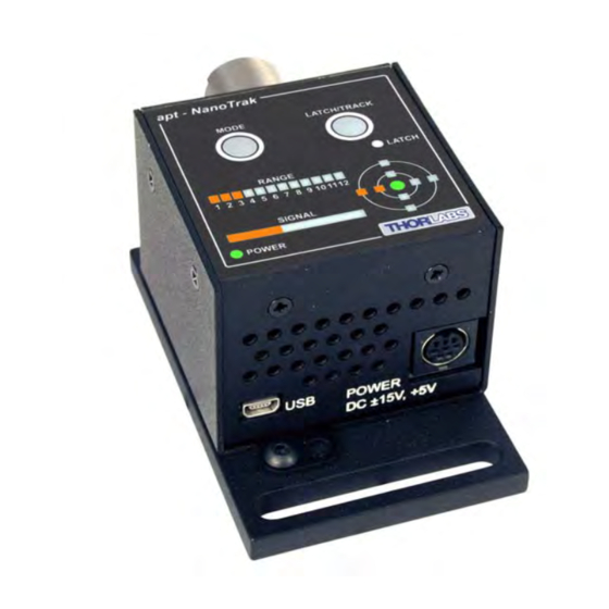
Page 20: Control Panel Buttons And Indicators
Chapter 4 times around the circle and, using the point on the circle where the power is highest, detects the direction in which the fibers need to move to maximize the po wer coupling. In order for the system to operate correctly in different applications, various software settings (explained in Section 6.2.) may need to be adjusted. -
Page 21: Track/Latch Button Operation
T-Cube NanoTrak Autoalignment Controller 4.2.1 Track/Latch Button Operation When in ‘T rack’ mode, the NanoTrak detects any drop in signal strength resulting from misalignment of the input and output optical devices, and makes positional adjustments (output DC offsets) to maintain maximum throughput. The ‘LATCH’ LED is not lit when TRACK mode is selected. -
Page 22: Basic Operation
Caution During item (7) ensure the power supply unit is isolated from the mains before connecting to the T-Cube units. Always power up the units by connecting their power supply to the mains. DO NOT connect the T-Cube units to a 'live' external power supply. Doing so (i.e. “hot plugging”) carries the risk of PERMANENT damage to the unit. - Page 23 T-Cube NanoTrak Autoalignment Controller Using the Range and Signal Bars. The RANGE and SIGNAL Bars should be considered together. The RANGE bar displays the current range of the internal power meter. Available ranges are as follows: RANGE 1 30 nA full scale RANGE 2 100 nA full scale RANGE 3...
- Page 24 Chapter 4 8) Depending on the range of tra vel of the pi ezo actuators, it is po ssible that the piezo range is not suffi cient to drive this stage to the max po wer position and in this case, the manual actuators should be adjusted to reposition the stage. The piezo position is indicated by the ‘TARGET display as follows: Using the Target Display The ‘target’...
-
Page 25: Using An External Power Meter
T-Cube NanoTrak Autoalignment Controller 9) Adjust the Y- an d Z-axis manual actuators as necessary to kee p the piezos around the mid-range position, i.e. for a 75V piezo, the piezo driver displays 37.5V and the TARGET display shows the green center LED lit - see Fig. 4.4. Fig. -
Page 26: Chapter 5 Pc Operation - Tutorial
Chapter 5 PC Operation - Tutorial 5.1 Introduction Note Familiarize yourself with stand alone operation of the NanoTrak (see Chapter 4) before attempting operation from the GUI panel. The following brief tutorial guides the user th rough a typical series of actions and parameter adjustments performed using the GUI p anel displayed by the APTUser utility. -
Page 27: Introduction
T-Cube NanoTrak Autoalignment Controller The APT User utility will be used throughout the rest of this tutorial to interface with the NanoTrak controller. 5.2 Building An Auto-alignment System - PC Operation 5.2.1 Introduction The TNA001 NanoTrak unit is designed to operate with two TPZ001 piezo T-Cubes, which provide the drive signals to the pi ezo actuators in the system. - Page 28 Chapter 5 Fig. 5.2 Typical Set Up - Rev 1 TPZ001 Units Caution During item (7) ensure the power supply unit is isolated from the mains before connecting to the T-Cube units. Always power up the units by connecting their power supply to the mains. DO NOT connect the T-Cube units to a 'live' external power supply.
- Page 29 10) Run the APTUser utility Start/All Programs/Thorlabs/APT/APT User. 11) Click the ‘Settings’ button on GUI panel of one of the Piezo Drivers. The Settings panel is displayed - see Fig. 5.3. Note. To identify the piezo unit associated with a GUI panel, click the ‘Ident’...
-
Page 30: Using Revision 1 Piezo Drivers On The Tch002 Hub
Chapter 5 16) Repeat items (12) to (16) for the remaining Piezo GUI panel. 17) On the NanoTrak GUI, click the ‘Settings’ button to display the Settings panel. 18) Select the Input/Output tab - see Fig. 5.4 19) Make the following parameter settings, as shown in Fig. 5.4 Input Signal Source - Select PIN (TIA) Input Voltage Range - Select 5V Range if a 75V piezo is being driven, or 10V Range for a 100V or 150V piezo... -
Page 31: Wiring And Software Settings For Revision 2 Piezo Drivers - Hub Operation
T-Cube NanoTrak Autoalignment Controller 5.2.4 Wiring and Software Settings for Revision 2 Piezo Drivers - Hub Operation Using the TCH002 hub greatly simplifies system wiring because the hub provides all the necessary power, signal and USB comms connections to all controller cubes. The following procedure describes a typical set up, with the TNA001 NanoTrak cube being used with a pair of Rev 2 TPZ001 piezo driver cubes on the TCH002 controller hub - see F ig. - Page 32 - see the Getting Started guide for more information. 11) Run the APTUser utility Start/All Programs/Thorlabs/APT/APT User. 12) Click the ‘Settings’ button on GUI of the Piezo Driver fitted in bay 1. The Settings panel is displayed. Note. To identify the piezo unit associated with a GUI panel, click the ‘Ident’...
- Page 33 T-Cube NanoTrak Autoalignment Controller 15) Click ‘OK to save the settings. 16) On the GUI panel, turn the ‘Output’ control to give a reading of 0V on the display. 17) Click the ‘Settings’ button on GUI of the Piezo Driver fitted in bay 2. The Settings panel is displayed 18) Make the following parameter settings, as shown in Fig.
-
Page 34: Revision 2 Piezo Driver Hub Mounting Options
Chapter 5 5.2.5 Revision 2 Piezo Driver Hub Mounting Options When the T-Cube NanoTrak and two Piezo Drivers are u sed together on the hub, signals can be routed via dedicated internal communication channels. These channels are selected via the piezo unit settings panel, or via the ‘MODE’ button on the top panel of the unit. - Page 35 T-Cube NanoTrak Autoalignment Controller Fig. 5.9 Bay Options and Associated Analog Input Source Settings...
-
Page 36: Basic Operation
Chapter 5 5.2.7 Basic Operation The general procedure involves setting the NanoTrak to ‘L atch’ (to lock the piezo positions - see Section 4.2.1.) an d using the manual actuators to a djust the stage position until some power is detected. Once this initial ‘first light’ position is achieved the NanoTrak is switched to ‘Track’... - Page 37 T-Cube NanoTrak Autoalignment Controller Using the Range and Relative Signal Bars. The Range and Relative Signal Bars should be considered together. The Range bar displays the current range of the internal power meter. Available ranges are as follows: RANGE 1 30 nA full scale RANGE 2 100 nA full scale...
- Page 38 Chapter 5 this case, the manual actuators should be adjusted to reposition the stage. The piezo position is indicated by the position of the ‘Circle in the display as follows: Using the Circle Display The circle diameter relates to the amplitude of the oscillation of the fiber. The position of the ‘circle’...
- Page 39 T-Cube NanoTrak Autoalignment Controller show about 73V (148V for a 150V piezo). This means that the piezo actuator must be recentered, and the position offset taken up by manual adjustment. 12) Adjust the Y- an d Z-axis manual actuators as necessary to kee p the piezos around the mid-range position, i.e.
-
Page 40: Using Two Nanotraks In The Same System
Chapter 5 5.2.8 Using Two NanoTraks in the Same System The NanoTrak scanning process uses a single frequency (and a highly selective discriminator similar to a rad io receiver) and it is possi ble to u se more than one NanoTrak T-Cube in a single optical path (and with a single detector). - Page 41 T-Cube NanoTrak Autoalignment Controller Fig. 5.11 Dual NanoTrak connections...
-
Page 42: Creating A Simulated Configuration Using Apt Config
To create a simulated configuration proceed as follows: 1) Run the APT Config utility - Start/All Programs/Thorlabs/APT/APT Config. 2) Click the 'Simulator Configuration' tab. Fig. 5.12 APT Configuration Utility - Simulator Configuration Tab 3) Enter ‘LAB1’... - Page 43 T-Cube NanoTrak Autoalignment Controller 4) In the 'Simulator' field, check the ‘Enable Simulator Mode’ box. The name of the most recently used configuration file is displayed in the 'Current Configuration' window. 5) In the ‘Control Unit’ field, select ‘NanoTrak T-Cube (TNA001)’.
-
Page 44: Programmed Operation
Chapter 5 6) Enter a 6 digit serial number. Note Each physical APT hardware unit is factory programmed with a unique 8 digit serial number. In order to simulate a set of ‘real’ hardware the Config utility allows an 8 digit serial number to be associated with each simulated unit. -
Page 45: Chapter 6 Software Reference
T-Cube NanoTrak Autoalignment Controller Chapter 6 Software Reference 6.1 GUI Panel Fig. 6.1 NanoTrak Software GUI Note The serial number of the TNA001 NanoTrak unit associated with the GUI panel, the APT server version number, and the version number (in brackets) of the embedded software running on the unit, are displayed in the top right hand corner. - Page 46 Chapter 6 If 'mW' is selected, readings are displayed or returned as power, generated using a Amp:Watt calibration factor specified either in the 'Settings; panel or by calling the SetUnitsMode method. Note This is not intended to be a calibrated power reading, but rather a convenient mechanism for converting current to power.
- Page 47 Track - push button control u sed to set th e NanoTrak to ' Track' mode, usin g both horizontal and vertical axe s to set a circular scan pattern. When tracking, the NanoTrak detects any drop in signal strength resulting from misalignment of the input and output devices, and makes positional adjustments to maintain the maximum.
- Page 48 compensation adjustment mode is set to 'Auto', the actual phase offset may be different to the diameter displayed. (see Section E.2.3. for further information). Loop Gain - displays the gain setting for the NanoTrak control loop. The gain can be set either by enterin g a value in the 'Settings' panel or by calling the SetLoopGain method.
-
Page 49: Nanotrak Settings Window
6.2 NanoTrak Settings Window When the 'Settings' button on the GUI p anel is clicked, the 'Settings' window is displayed. This panel allows data such scan circle frequency and diameter, and loop gain to be entered. The various parameters are described below. 6.2.1 Tracking tab Fig. - Page 50 Chapter 6 If 'LUT Adjust' is specified, the circle diameter is adjusted automatically, using a table of range dependent diameter values (set in the Diameter LUT parameters or by calling the SetCircDiaLUTVal method). Diameter LUT - this setting enables a look up table (LUT) of circle diameter values (in NanoTrak units) to be specified as a function of input range.
-
Page 51: Input/Output Tab
Persist Settings to Hardware - Many of the parameters that ca n be set for the NanoTrak T-Cube can be stored (persisted) within the unit itself, such that when the unit is next powered up these settings are applied automatically. This is particularly important when the driver is being used manually in the absence of a PC and USB link. - Page 52 Chapter 6 PIN (TIA) Reading Units Units Mode - th is parameter specifies the units relating to the i nput signal measured by the NanoTrak, and is applicable only if a PIN (TIA) input source has been specified. If Amps is selected, readings are displayed or returned in mA, i.e. the raw PIN current input signal to the internal amplifier.
-
Page 53: Nanotrak Screen Tab
T-Cube NanoTrak Autoalignment Controller the output voltage range is selected, so the 10V range should be selected for both 75V and 150V piezo actuators. Therefore, if revision 2 piezo cubes are used, select 10V range. If revision 1 cubes are used, select 5V for 75V actuators and 10V for 150V actuators. Voltage Routing- the NanoTrak control signals (sine and cosine) are always output on the external SMA connectors (LV OUT CH1 and LV OUT CH2). - Page 54 Chapter 6 circle can be positioned by using the mouse. This feature allows manual repositioning of the piezos, e.g. to enable investigation of the region of interest to look for side peaks, artifacts etc. The circle can be moved either by click and drag, or b y moving an incremental distances per mouse click.
-
Page 55: Tia Tab
T-Cube NanoTrak Autoalignment Controller 6.2.4 TIA Tab Fig. 6.6 NanoTrak Settings panel - TIA tab This panel is used to mod ify the autoranging and output characteristics of the NanoTrak input amplifier circuit (Trans-impedance amplifier (TIA) circuit). Input Signal Amplifier (TIA) Autoranging Settings Auto-ranging Mode - when auto-ranging mode is selected on the GUI panel, range changes occur wh enever the input signal reaches the upper or low er end of the currently set range. - Page 56 Chapter 6 Settle Samples – This parameter determines the amount of averaging applied to the signal before a utoranging takes p lace. Higher SettleSamples values improve the signal to noise ratio when dealing with noi sy feedback signals. However, higher SettleSamples values also slow down the autoranging response.
-
Page 57: Appendix A Connector Pinout Details
A.1 Power Connector A.1.1 Pin Identification Thorlabs recommends that the Na noTrak cube i s operated with T horlabs power supply TPS002, as it was specifically designed for use with this product. However, to enable customers to use th e cube in install ations where a ±15V and 5V power is already available, the pi ezo cube can be operated with a di fferent external power supply, such as a bench or lab supply. -
Page 58: Appendix B Preventive Maintenance
The equipment contains no user serviceable parts. There is a risk of electrical shock if the equipment is operated with the covers removed. Only personnel authorized by Thorlabs Ltd. and trained in the maintenance of this equipment should remove its covers or attempt any repairs or adjustments. -
Page 59: Appendix C Specifications And Associated Parts
Appendix C Specifications and Associated Parts C.1 Specifications Parameter Value Optical Power Measurement PIN Photo-Diode FC/PC Fiber Input Si or InGaAs Detector 30nA to 10mA Photocurrent Optical Power Monitor (SMA) 0 to 10 V Signal Phase Compensation -180° to 180° NanoTraking Output Voltage 0 to 10 V... - Page 60 Appendix C C.2 Associated Products Product Name Part Number InGaAs Detector NTA007 Silicon Detector NTA009 T-Cube Piezo Driver TPZ001 2-Way Power Supply Unit TPS002 T-Cube Controller Hub & Power Supply TCH002 SMA Male to SMA Male Cable 6” CA2906 SMA Male to SMA Male Cable 12” CA2912 SMA Male to SMA Male Cable 18”...
-
Page 61: Appendix D Nanotrak Control Method Summary
Appendix D NanoTrak Control Method Summary The 'NanoTrak' ActiveX Control provides the functionality required for a clie nt application to control one or more NanoTrak auto-alignment controller products. The NanoTrak system comes in be nchtop (BNT001), T-Cube (TNA001) and 19" rack modular (MNA601) formats, all of wh ich are covered by the NanoTrak ActiveX Control. - Page 62 Appendix D GetCircFreq Obtains the circle scanning frequency GetCircHomePos Returns the circle home po sition horizontal and vertical coordinates GetCircPosReading Obtains the current horizontal and vertical position of the circle GetInputSrc Gets the HV amplifier input source. GetLoopGain Returns the feedback loop gain GetLPFilter Obtains the cut off frequency of the digital low pass (LP) filter applied to output readings of the internal...
- Page 63 T-Cube NanoTrak Autoalignment Controller SetAmpFeedbackSig Sets the feedback signal type (AC or DC). SetAmpOutputParams Sets the HV amplifier output parameters. SetAmpControlMode Sets the loop operating mode (open/closed). SetCircDia Sets the user circle diameter SetCircDiaLUTVal Sets the LUT value for the spe cified NanoTrak range, when automatic look up table (LUT) diameter adjustment mode is enabled.
- Page 64 Appendix D TNA_GetSigOutputParams Returns parameter valu es which control the NanoTrak output signal ranges and the way in which these signals are routed to th e associated piezo drivers. TNA_SetDispIntensity Sets the intensity of the LED display on the front of the unit TNA_SetSigOutputParams Sets parameter values which control the Nan oTrak...
-
Page 65: Appendix E The Nanotrak Principle Of Operation
Appendix E The NanoTrak Principle Of Operation E.1 Introduction For simplicity, the following example refers to the alignment of two opposing butt coupled single mode fibers, however the principles of operation are method is equally valid for the physical alignment of any two opposing optically coupled faces or indeed any two objects that can provide a feedback signal (voltage) that varies as a function of their alignment with respect to each other.. - Page 66 Appendix E E.2 How the NanoTrak Maximizes Optical Power E.2.1 General Principle To understand the principles involved in the alignment, consider the operation in a single axis. Wh en two fib ers are a ligned, maximum po wer is transmitted b etween them, and if the fiber is moved a few microns to the left (Fig.
- Page 67 T-Cube NanoTrak Autoalignment Controller However, piezo transducers are unip olar and to achieve a positive an d negative adjustment either side of center, the piezo must be at its center of travel when the error signal is zero. This is achieved by adding an offset voltage to the error signal. Now, the range of the piezo is typically 20 to 30 µm, while the fiber is oscillated by 2 or 3 microns.
- Page 68 Appendix E the subsequent drop in po wer and corrects for the movemen t to maintain the maximum. This is called tracking. E.2.2 Circle Size and Gain Control Given that move ment of two opposing fibers produces variations in the coupled power, the very act of automatically aligning the fibers to increase the coupled power may cause unwanted disturbances to the signal path.
- Page 69 T-Cube NanoTrak Autoalignment Controller This LUT diameter adjustment mode allows appropriate circle diameters to be applied on an application specific basis. The loop gain can also effect system stability. If the gain is too high, the circle moves erratically, whereas too low a setting results in the circle ‘floating’ around the edge of the screen.
-
Page 70: Appendix F Regulatory
Appendix F Regulatory F.1 Declarations Of Conformity F.1.1 For Customers in Europe This equipment has been tested and found to comply with the EC Directives 89/336/EEC ‘EMC Directive’ and 73/23/EEC ‘Low Voltage Directive’ as amended by 93/68/EEC. Compliance was demonstrated by conformance to the following specifications which have been listed in the Official Journal of the European Communities: Safety EN61010: 2001 Installation Category II, Polution Degree II. - Page 71 • left over parts of units disassembled by the user (PCB's, housings etc.). If you wish to return a unit for waste recovery, please contact Thorlabs or your nearest dealer for further information. F.2.2 Waste treatment on your own responsibility If you do not return an "end of life"...
- Page 72 Thorlabs Ltd 1 Saint Thomas Place, Cambridgeshire Business Park, Ely, Cambridgeshire CB7 4EX declare that the TNA001/IR T-Cube auto-alignment controller complies with the following Harmonized European Standards: BS EN 61326-1:1998 BS EN 61000-3-2: 2000 BS EN 61000-3-3: 1995 EN 61010-1: 2001...
- Page 73 T-Cube NanoTrak Autoalignment Controller...
- Page 74 Chapter 6 HA0165T Rev 4 May 2012...
-
Page 75: Appendix G Thorlabs Worldwide Contacts
UK and Ireland Thorlabs, Inc. Thorlabs Ltd. sales@thorlabs.com sales.uk@thorlabs.com techsupport@thorlabs.com techsupport.uk@thorlabs.com Europe Scandinavia Thorlabs GmbH Thorlabs Sweden AB europe@thorlabs.com scandinavia@thorlabs.com France Brazil Thorlabs SAS Thorlabs Vendas de Fotônicos Ltda. sales.fr@thorlabs.com brasil@thorlabs.com Japan China Thorlabs Japan, Inc. Thorlabs China sales@thorlabs.jp chinasales@thorlabs.com... - Page 76 www.thorlabs.com...
Need help?
Do you have a question about the TNA001/IR and is the answer not in the manual?
Questions and answers