Table of Contents
Advertisement
Quick Links
Advertisement
Table of Contents

Subscribe to Our Youtube Channel
Related Manuals for THORLABS T-Cube NanoTrak TNA001/IR


Summary of Contents for THORLABS T-Cube NanoTrak TNA001/IR
- Page 1 TNA001/IR T-Cube NanoTrak Controller Kinesis User Guide Original Instructions...
-
Page 2: Table Of Contents
Contents Chapter 1 For Your Safety ................4 1.1 Safety Information .................. 4 1.2 General Warnings .................. 4 Chapter 2 Overview and Setup ..............5 2.1 Introduction ..................... 5 2.2 Power Options ..................6 2.3 Kinesis PC Software Overview ............... 7 2.3.1 Introduction ...................... - Page 3 Appendix A Connector Pinout Details ............52 Appendix B Preventive Maintenance ............53 Appendix C Specifications and Associated Parts ........54 Appendix D The NanoTrak Principle Of Operation ........56 Appendix E Regulatory ................61 Appendix F Thorlabs Worldwide Contacts ..........55...
-
Page 4: Chapter 1 For Your Safety
To minimize the possibility of this happening it is strongly recommended that any such modes that result in prolonged unresponsiveness be disabled before the software is run. Please consult your system administrator or contact Thorlabs technical support for more details. -
Page 5: Chapter 2 Overview And Setup
Chapter 2 Overview and Setup 2.1 Introduction The T-Cube NanoTrak Controller represents the latest developments in automated optical alignment technology. It is designed for use in photonics device alignment and is ideal for low volume device assembly, characterization, and mapping. This auto alignment T-Cube unit is used together with a pair of external piezo amplifier channels (KPZ101 K-Cube Piezo Drivers) to provide a complete solution for manipulating piezo actuated nano-positioning stages to align devices to the 10nm regime. -
Page 6: Power Options
(Chapter 6) covers all operating modes and parameters in detail. 2.2 Power Options For power, a compact two-way power supply unit (TPS002) is available from Thorlabs allowing up to 2 K-Cube Piezo Drivers to be powered from a single mains outlet. This power supply unit is also designed to take up minimal space and can be mounted to the optical table in close proximity to the driver units, connected via short power leads. -
Page 7: Kinesis Pc Software Overview
T-Cube NanoTrak Autoalignment Controller 2.3 Kinesis PC Software Overview 2.3.1 Introduction The K-Cube range of controllers share many of the benefits. These include USB connectivity (allowing multiple units to be used together on a single PC), fully featured Graphical User Interface (GUI) panels, and extensive software function libraries for custom application development. - Page 8 Chapter 2 Consider the supplied for a TNA001 NanoTrak controller unit (one panel is displayed for each controller). This Control provides a complete user graphical instrument panel to al low the NanoTrak unit to be manually operated, as well as a complete set of software functions (often called methods) to allow all parameters to be set and NanoTrak control operations to be automated by a client application.
-
Page 9: Software Upgrades
This is available either by pressing the F1 key when running the Kinesis server, or via the Start menu, Start\Programs\Thorlabs\Kinesis\Kinesis Help. 2.3.3 Software Upgrades Thorlabs operate a policy of continuous product development and may issue software upgrades as necessary. The latest software can be downloaded from the ‘services’ section of www.thorlabs.com. -
Page 10: Chapter 3 Installation & Initial Software Settings
+44 (0)1353 654440 and ask for Technical Support. DO NOT CONNECT THE CONTROLLER TO YOUR PC YET 1) Go to Services/Down loads at www.thorlabs.com and do wnload the Kin esis software. 2) Run the .exe file and follow the on-screen instructions. -
Page 11: Mechanical Installation
(KCH301 and KCH601). ) are also available - see Section 2.2. for further details. Full instructions on the fitting and use of the controller hub are contained in the handbook for the units, available at www.thorlabs.com. Caution When siting the unit, it should be positioned so as not to impede the operation of the control panel buttons. -
Page 12: Removing The Baseplate
Chapter 3 3.2.3 Removing the Baseplate The baseplate must be removed before the rubber feet (supplied) can be fitted, or the unit is connected to the USB controller hub. Detail A Detail B Baseplate attachment screws Baseplate removed and rubber feet fitted Fig. -
Page 13: Electrical Installation
TCH002 hub - see Section 5.3.2., these outputs can be connected to an oscilloscope to enable the drive signal of the piezo actuator to be monitored. Note Thorlabs supply a variety of SMA to BNC and SMC to BNC adaptor and extension cables. Please see our catalog, or visit www.thorlabs.com for further details. -
Page 14: Supply Voltage And Current Requirements
Chapter 3 3.3.2 Supply Voltage and Current Requirements Supply Minimum Maximum Max Operating Current +4.9V +5.1V 400 mA +15V +14.5V +15.5V 250 mA -15V -14.5V -15.5V 100 mA 3.3.3 Connecting To A Standalone Power Supply Warning The unit must be connected only to a DC supply as detailed in Section 3.3.2. -
Page 15: Using The Usb Controller Hub
T-Cube NanoTrak Autoalignment Controller Thorlabs offers a compact, two-way power supply unit (TPS002), allowing up to two NanoTrak or Piezo driver K-Cubes to be pow ered from a single mains outlet. However, if an e xternal supply is to be used, see Appendix A.1 for power supply connector pin out details. -
Page 16: Detector Heads And Cables
KPZ101 Piezo Cube pair configured to pick these signal up via SMA inputs. This will require small SMA to SMA connection cables (e.g. CA2912), various lengths of which are available from Thorlabs. 3.3.5 Detector Heads and Cables The OPTICAL/PIN IN connector on the rear panel of the NanoTrak has been designed to increase the interchangeability of the optical input source. -
Page 17: Chapter 4 Using The Nanotrak Without A Pc
Chapter 4 Using the NanoTrak Without A PC 4.1 Introduction The NanoTrak T-Cube has been designed specifically to operate with the KPZ101 Piezo Driver T-Cubes. Together, these units comprise an acti ve-feedback optical alignment system that allows the user to align optical fibers and optimize the coupling of light into and out of photonics devices. -
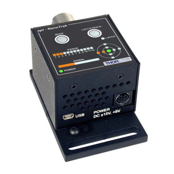
Page 18: Control Panel Buttons And Indicators
Chapter 4 times around the circle and, using the point on the circle where the power is highest, detects the direction in which the fibers need to move to maximize the po wer coupling. In order for the system to operate correctly in different applications, various software settings (explained in Section 6.2.) may need to be adjusted. -
Page 19: Track/Latch Button Operation
T-Cube NanoTrak Autoalignment Controller 4.2.1 Track/Latch Button Operation When in ‘T rack’ mode, the NanoTrak detects any drop in signal strength resulting from misalignment of the input and output optical devices, and makes positional adjustments (output DC offsets) to maintain maximum throughput. The ‘LATCH’ LED is not lit when TRACK mode is selected. -
Page 20: Basic Operation
Chapter 4 Caution During item (7) ensure the power supply unit is isolated from the mains before connecting to the T-Cube units. Always power up the units by connecting their power supply to the mains. DO NOT connect the T-Cube units to a 'live' external power supply. - Page 21 T-Cube NanoTrak Autoalignment Controller Using the Range and Signal Bars. The RANGE and SIGNAL Bars should be considered together. The RANGE bar displays the current range of the internal power meter. Available ranges are as follows: RANGE 1 30 nA full scale RANGE 2 100 nA full scale RANGE 3...
- Page 22 Chapter 4 8) Depending on the range of tra vel of the pi ezo actuators, it is po ssible that the piezo range is not suffi cient to drive this stage to the max po wer position and in this case, the manual actuators should be adjusted to reposition the stage. The piezo position is indicated by the ‘TARGET display as follows: Using the Target Display The ‘target’...
-
Page 23: Using An External Power Meter
T-Cube NanoTrak Autoalignment Controller 9) Adjust the Y- an d Z-axis manual actuators as necessary to kee p the piezos around the mid-range position, i.e. for a 75V piezo, the piezo driver displays 37.5V and the TARGET display shows the green center LED lit - see Fig. 4.4. Piezo Controller Piezo Controller 37.5... -
Page 24: Chapter 5 Pc Operation - Tutorial
This tutorial shows how the Kinesis application provides all of the functionality necessary to operate the hardware. Power up the hardware, and wait until the TNA001 has finished booting up, then run the Kinesis software - Start/All Programs/Thorlabs/Kinesis/Kinesis. - Page 25 T-Cube NanoTrak Autoalignment Controller Fig. 5.1 Typical User Screen The Kinesis software will be used throughout the rest of this tutorial to interface with the position aligner.
-
Page 26: Building An Auto-Alignment System - Pc Operation
Chapter 5 5.3 Building An Auto-alignment System - PC Operation 5.3.1 Introduction The TNA001 NanoTrak unit is designed to operate with two KPZ101 piezo K-Cubes, which provide the drive signals to the piezo actuators in the system. The following sections describe the electrical connections and software settings for both standalone and hub use. - Page 27 - see the Getting Started guide for more information. 11) Run the Kinesis software. Start/All Programs/Thorlabs/Kinesis/Kinesis. 12) Click the ‘Settings’ button on GUI of the Piezo Driver fitted in bay 1. The Settings panel is displayed. Note. To identify the piezo unit associated with a GUI pan el, click the ‘Ident’...
- Page 28 Chapter 5 Analogue Input Input Mode - Select Analogue Channel 1 Loop Mode - Select Open Loop 14) If desired, click the ‘Persist Settings To Hardware’ box. These settings will then be loaded on each power up cycle. Fig. 5.3 Piezo Driver Settings 15) Click ‘OK to save the settings.
- Page 29 T-Cube NanoTrak Autoalignment Controller 19) On the NanoTrak GUI, click the ‘Settings’ button to display the Settings panel. 20) Select the Input/Output tab- see Fig. 5.4 21) Make the following parameter settings, as shown in Fig. 5.4 Input Signal Source - Select PIN (TIA) Input Voltage Range - Select 10V Range Voltage Routing - Select SMA + Hub 22) If desired, click the ‘Persist Settings To Hardware’...
-
Page 30: Piezo Driver Hub Mounting Options
Chapter 5 5.3.3 Piezo Driver Hub Mounting Options When the T-Cube NanoTrak and two Piezo Drivers are u sed together on the hub, signals can be routed via dedicated internal communication channels. These channels are selected via the piezo unit settings panel, or via the ‘MODE’ button on the top panel of the unit. - Page 31 T-Cube NanoTrak Autoalignment Controller bay 1 bay 3 TPZ001 TPZ001 Hub Channel 2 Hub Channel 1 Piezo Controller Piezo Controller MODE LATCH/TRACK LATCH RANGE 1 2 3 4 5 6 7 8 9 101112 MENU MENU SIGNAL POWER bay 3 TPZ001 Hub Channel 1 Piezo Controller...
-
Page 32: Basic Operation
Chapter 5 5.3.5 Basic Operation The general procedure involves setting the NanoTrak to ‘L atch’ (to lock the piezo positions - see Section 4.2.1.) an d using the manual actuators to a djust the stage position until some power is detected. Once this initial ‘first light’ position is achieved the NanoTrak is switched to ‘Track’... - Page 33 T-Cube NanoTrak Autoalignment Controller Using the Range and Relative Signal Bars. The Range and Relative Signal Bars should be considered together. The Range bar displays the current range of the internal power meter. Available ranges are as follows: RANGE 1 30 nA full scale RANGE 2 100 nA full scale...
- Page 34 Chapter 5 this case, the manual actuators should be adjusted to reposition the stage. The piezo position is indicated by the position of the ‘Circle in the display as follows: Using the Circle Display The circle diameter relates to the amplitude of the oscillation of the fiber. The position of the ‘circle’...
- Page 35 T-Cube NanoTrak Autoalignment Controller This means that in order to locate maximum power, the piezo is moving the stage more to the right. But, the circle is near the edge of the screen, which also indicates that the piezo is near the limit of its travel to the right; the associated piezo driver will show about 73V (148V for a 150V piezo).
-
Page 36: Using Two Nanotraks In The Same System
Chapter 5 5.3.6 Using Two NanoTraks in the Same System The NanoTrak scanning process uses a single frequency (and a highly selective discriminator similar to a rad io receiver) and it is possi ble to u se more than one NanoTrak T-Cube in a single optical path (and with a single detector). - Page 37 T-Cube NanoTrak Autoalignment Controller Fig. 5.8 Dual NanoTrak connections...
-
Page 38: Programmed Operation
Chapter 5 5.4 Programmed Operation Note Familiarize yourself with operation of the NanoTrak from the GUI panel (see Section 5.3.) before attempting programmed operation. The functionality required for a client application to control the NanoTrak unit is provided by the NanoTrak Control within the Kinesis server, with manual operation being facilitated via the front panel buttons (see Section 4.3.) or via the GUI panel (see Section 5.3.). -
Page 39: Chapter 6 Software Reference
Chapter 6 Software Reference 6.1 GUI Panel Fig. 6.1 NanoTrak Software GUI Note The serial number of the TNA001 NanoTrak unit associated with the GUI panel is displayed in the top right hand corner. This information should always be provided when requesting customer support. Range indicator - displays the current ra nge of the internal power meter. - Page 40 Chapter 6 If 'mW' is selected, readings are displayed or returned as power, generated using a Amp:Watt calibration factor specified either in the 'Settings; panel or by calling the SetUnitsMode method. Note This is not intended to be a calibrated power reading, but rather a convenient mechanism for converting current to power.
- Page 41 T-Cube NanoTrak Autoalignment Controller Track - pu sh button con trol used to set the Nan oTrak to ' Track' mode, using both horizontal and vertical axes to set a ci rcular scan pa ttern. When tracking, the NanoTrak detects any drop in signal strength resulting from misalignment of the input and output devices, and makes positional adjustments to maintain the maximum.
- Page 42 Chapter 6 compensation adjustment mode is set to 'Auto', the actual phase offset may be different to the diameter displayed. (see Section D.2.3. for further information). Loop Gain - displays the gain setting for the NanoTrak control loop. The gain can be set ei ther by entering a value in the ' Settings' panel or by call ing the SetLoopGain method.
-
Page 43: Nanotrak Settings Window
T-Cube NanoTrak Autoalignment Controller 6.2 NanoTrak Settings Window When the 'Settings' button on th e GUI pan el is clicked, the 'Settings' window is displayed. This panel allows data such scan circle frequency and diameter, and loop gain to be entered. The various parameters are described below. 6.2.1 Tracking tab Fig. - Page 44 Chapter 6 a value of 5.0 corresponding to one half the range of piezo motion - see Section D.2.2. for further details and helpful hints on setting the correct circle size. If the Diameter Mode is set to 'LUT ', the circle diameter is adjusted automatically, using a tabl e of ran ge dependent diameter values set in the LUT TIA Range parameters.
- Page 45 T-Cube NanoTrak Autoalignment Controller Persist Settings to The Device - Many of the parameters that can be set fo r the NanoTrak T-Cube can be stored (persisted) within the unit itself, such that when the unit is next powered up these settings are applied automatically. This is particularly important when the driver is being used manually in the absence of a PC and USB link.
-
Page 46: Input/Output Tab
Chapter 6 6.2.2 Input/Output tab Fig. 6.3 NanoTrak Settings panel - Input/Output Tab Input Signal Input Signal Source - the input source can be set to ‘ PIN (TIA) Input’ or ‘1 0V SMA input’. The PIN (TIA) Input option should be used when NanoTraking to optimize a PIN current feedback signal. - Page 47 T-Cube NanoTrak Autoalignment Controller amplifier circuit is bypassed and ranging functionality (as displayed on the GUI) is inoperative. The input range is 10V full scale. PIN (TIA) Reading Units Units Mode - this p arameter specifies the u nits relating to the input signal measured by the NanoTrak, and is applicable only if a PIN (TIA) input source has been specified.
- Page 48 Chapter 6 On some older piezo drivers, th e external SMA in put always provides a x15 amplification to the high voltage (HV) output, so a full 10V output voltage results in 150V HV output. For piezo actuators with a 75V maximum voltage range, this would result in the actuator being overdriven.
- Page 49 T-Cube NanoTrak Autoalignment Controller Settings are entered as a percentage of full range. Note The Upper limit must be higher than the Lower limit. If an attempt is made to enter a value for the Lower limit which is higher than the Upper limit, an error message is generated.
-
Page 50: Display Tab
Chapter 6 6.2.3 Display Tab Fig. 6.4 NanoTrak Settings panel - NanoTrak Screen Tab Display Intensity - determines the brightness of the control panel display. Enter a value from 0 to 255. Display Sometimes, it may be u seful to explore the area o f interest by manu ally repositioning the two pi ezos driven by the Na noTrak. - Page 51 T-Cube NanoTrak Autoalignment Controller Horizontal & Vertical Increments The circle can be positioned by clicking in the NanoTrak display screen. These parameters determine the d istance moved per mouse click. T he incremental distance can be set for each axis, in NT units or microns - see the Display Units parameter.
-
Page 52: Appendix A Connector Pinout Details
A.1 Power Connector A.1.1 Pin Identification Thorlabs recommends tha t the N anoTrak cube is ope rated with Thorlabs power supply TPS002, as it was specifically designed for use with this product. However, to enable customers to use the cube in in stallations where a ±15V and 5V power is already available, the piezo cube can be operated with a different external power supply, such as a bench or lab supply. -
Page 53: Appendix B Preventive Maintenance
The equipment contains no user serviceable parts. There is a risk of electrical shock if the equipment is operated with the covers removed. Only personnel authorized by Thorlabs Ltd. and trained in the maintenance of this equipment should remove its covers or attempt any repairs or adjustments. -
Page 54: Appendix C Specifications And Associated Parts
Appendix C Specifications and Associated Parts C.1 Specifications Parameter Value Optical Power Measurement PIN Photo-Diode FC/PC Fiber Input Si or InGaAs Detector 30nA to 10mA Photocurrent Optical Power Monitor (SMA) 0 to 10 V Signal Phase Compensation -180° to 180° NanoTraking Output Voltage 0 to 10 V... -
Page 55: Appendix F Thorlabs Worldwide Contacts
T-Cube NanoTrak Autoalignment Controller C.2 Associated Products Product Name Part Number InGaAs Detector NTA007 Silicon Detector NTA009 K-Cube Piezo Driver KPZ101 2-Way Power Supply Unit TPS002 K-Cube Controller Hub & Power Supply KCH301/KCH601 SMA Male to SMA Male Cable 6” CA2906 SMA Male to SMA Male Cable 12”... -
Page 56: Appendix D The Nanotrak Principle Of Operation
Appendix D The NanoTrak Principle Of Operation D.1 Introduction For simplicity, the fo llowing example refers to the alignment of two opp osing butt coupled single mode fibers, however the principles of operation are method is equally valid for the physical alignment of any two opposing optically coupled faces or indeed any two objects that can provide a feedback signal (voltage) that varies as a function of their alignment with respect to each other.. - Page 57 T-Cube NanoTrak Autoalignment Controller D.2 How the NanoTrak Maximizes Optical Power D.2.1 General Principle To understand the principles involved in the alignment, consider the operation in a single axis. Wh en two fibers are a ligned, maximum p ower is transmitted between them, and if the fiber i s moved a few microns to the left (Fi g.
- Page 58 Appendix D However, piezo transducers are unipolar and to achieve a positive and negative adjustment either side of center, the piezo must be at its center of travel when the error signal is zero. This is achieved by adding an offset voltage to the error signal. Now, the range of the piezo is typically 20 to 30 µm, while the fiber is oscillated by 2 or 3 microns.
- Page 59 T-Cube NanoTrak Autoalignment Controller the subsequent drop in power and corrects for the movement to ma intain the maximum. This is called tracking. D.2.2 Circle Size and Gain Control Given that movement of two opposing fibers produces variations in the coupled power, the very act of automatically aligning the fibers to increase the coupled power may cause unwanted disturbances to the signal path.
- Page 60 Appendix D This LUT diameter adjustment mode allows appropriate circle diameters to be applied on an application specific basis. The loop gain can also effect system stability. If the gain is too high, the circle moves erratically, whereas too low a setting results in the circle ‘floating’ around the edge of the screen.
-
Page 61: Appendix E Regulatory
Appendix E Regulatory E.1 Declarations Of Conformity E.1.1 For Customers in Europe This equipment has been tested and found to comply with the EC Directives 89/336/EEC ‘EMC Directive’ and 73/23/EEC ‘Low Voltage Directive’ as amended by 93/68/EEC. Compliance was demonstrated by conformance to the following specifications which have been listed in the Official Journal of the European Communities: Safety EN61010: 2001 Installation Category II, Polution Degree II. - Page 62 • left over parts of units disassembled by the user (PCB's, housings etc.). If you wish to return a unit for waste recovery, please contact Thorlabs or your nearest dealer for further information. E.2.2 Waste treatment on your own responsibility If you do not return an "end of life"...
- Page 63 T-Cube NanoTrak Autoalignment Controller E.3 CE Certificate E C Declaration of Conformity Thorlabs Ltd 1 Saint Thomas Place, Cambridgeshire Business Park, Ely, Cambridgeshire CB7 4EX declare that the TNA001/IR T-Cube auto-alignment controller complies with the following Harmonized European Standards: BS EN 61326-1:1998...
- Page 64 Appendix E HA0165T Rev 4K Sept 2017...
- Page 65 Germany Fax: +46-31-703-40-45 Tel: +49-(0)8131-5956-0 www.thorlabs.com Fax: +49-(0)8131-5956-99 Email: scandinavia@thorlabs.com www.thorlabs.de Email: europe@thorlabs.com Brazil Thorlabs Vendas de Fotônicos Ltda. Rua Riachuelo, 171 France Thorlabs SAS São Carlos, SP 13560-110 109, rue des Côtes Brazil 78600 Maisons-Laffitte Tel: +55-16-3413 7062 France...
- Page 66 Thorlabs Inc. Thorlabs Ltd. 56 Sparta Ave Saint Thomas Place, Ely Newton, NJ07860 Cambridgeshire CB7 4EX, Tel: +1 973 579 7227 Tel: +44 (0) 1353 654440 Fax: +1 973 300 3600 Fax: +44 (0) 1353 654444 www.thorlabs.com www.thorlabs.com...
Need help?
Do you have a question about the T-Cube NanoTrak TNA001/IR and is the answer not in the manual?
Questions and answers