Table of Contents
Advertisement
Quick Links
Advertisement
Table of Contents

Related Manuals for THORLABS TIM101


Summary of Contents for THORLABS TIM101
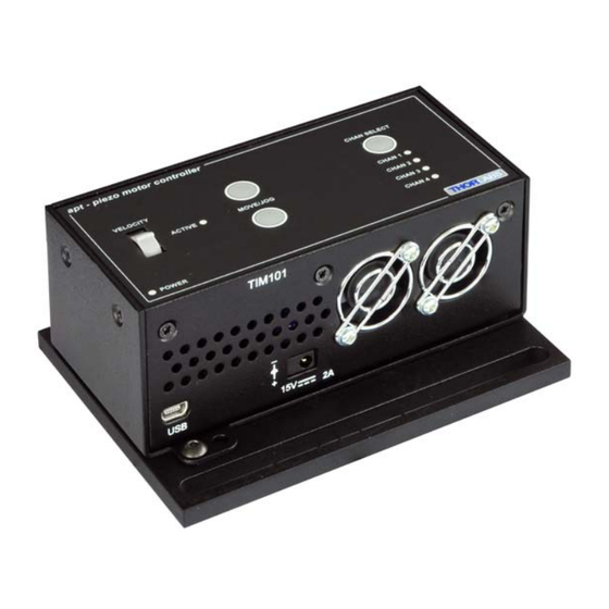
- Page 1 TIM101 Piezo Inertia Motor Controller User Guide Original Instructions...
-
Page 2: Table Of Contents
Contents Chapter 1 1 For Your Safety ................ 4 1.1 Safety Information .................. 4 1.2 General Warnings .................. 4 Chapter 2 Overview and Setup ..............5 2.1 Introduction ..................... 5 2.2 T-Cube Controller Hub ................6 2.3 APT PC Software Overview ..............7 Chapter 3 Getting Started ................ - Page 3 Appendix A Rear Panel Connector Pinout Details ........34 Appendix B Preventive Maintenance ............35 Appendix C Specifications................36 Appendix D Piezo Motor Control Method Summary ......... 38 Appendix E Piezo Operation - Background ..........40 Appendix F Regulatory ................43 Appendix G Thorlabs Worldwide Contacts ..........47...
-
Page 4: Chapter 1 For Your Safety
This product generates, uses and outputs high voltages from the SMC connector (HV Output) that are hazardous and can cause serious injury. In any installation that uses the TIM101 it is the user’s responsibility to ensure adequate insulation and precuations are taken to avoid shock risk. Cables for HV Out must be rated for 250 V RMS. -
Page 5: Chapter 2 Overview And Setup
Chapter 2 Overview and Setup 2.1 Introduction The TIM101 Piezo Inertia Motor Controller is designed to control our series of piezo inertia-driven positioning stages. It offers 4 channels of stand-alone manual control (one channel at a time) for continuous movement/jogging and remote PC control via USB. -
Page 6: T-Cube Controller Hub
For power, a compact multi-way power supply unit (TPS008) is available from Thorlabs allowing up to 4 T-Cube Drivers to be powered from a single mains outlet. This power supply unit is also designed to take up minimal space and can be mounted to the optical table in close proximity to the driver units, connected via short power leads. -
Page 7: Apt Pc Software Overview
TIM101 Piezo Motor Controller 2.3 APT PC Software Overview 2.3.1 Introduction As a member of the APT range of controllers, the T-Cube Piezo Inertia Motor Controller shares many of the associated software benefits. This includes USB connectivity (allowing multiple units to be used together on a single PC), fully featured Graphical User Interface (GUI) panels, and extensive software function libraries for custom application development. - Page 8 Chapter 2 2.3.2 APTUser Utility The APTUser application allows the user to interact with a number of APT hardware control units connected to the host PC. This program displays multiple graphical instrument panels to allow multiple APT units to be controlled simultaneously. All basic operating parameters can be altered and, similarly, all operations (such as motor moves) can be initiated.
- Page 9 TIM101 Piezo Motor Controller 2.3.3 APT Config Utility There are many system parameters and configuration settings associated with the operation of the APT Server. Most can be directly accessed using the various graphical panels, however there are several system wide settings that can be made 'off-line' before running the APT software.
- Page 10 Chapter 2 2.3.4 APT Server (ActiveX Controls) ActiveX Controls are re-usable compiled software components that supply both a graphical user interface and a programmable interface. Many such Controls are available for Windows applications development, providing a large range of re-usable functionality.
- Page 11 F1 key when running the APT server, or via the Start menu, Start\Programs\Thorlabs\APT\APT Help. 2.3.5 Software Upgrades Thorlabs operate a policy of continuous product development and may issue software upgrades as necessary. Note When the firmware is updated, the colling fans will run at maximum speed...
-
Page 12: Chapter 3 Getting Started
Thorlabs on +44 (0)1353 654440 and ask for Technical Support. DO NOT CONNECT THE CONTROLLER TO YOUR PC YET 1) Go to Services/Downloads at www.thorlabs.com and download the APT software. 2) Run the .exe file and follow the on-screen instructions. -
Page 13: Mechanical Installation
TIM101 Piezo Motor Controller 3.2 Mechanical Installation Warning The safety of any system incorporating this equipment is the responsibility of the person performing the installation. 3.2.1 Environmental Conditions Warning Operation outside the following environmental limits may adversely affect operator safety. - Page 14 Chapter 3 3.2.3 Removing the Baseplate In order to help mounting the unit to an optical table, a baseplate is provided with the unit. However, if the unit is required to be operated free-standing (for example on a bench), the baseplate can be removed and rubber feet fitted. The baseplate must be removed before the rubber feet (supplied) can be fitted, or the unit is connected to the USB controller hub..
-
Page 15: Electrical Installation
3.3.1 Connecting a Piezo Motor Fig. 3.2 Rear Panel Connections MOT Terminals - (SMC Connectors) The unit is supplied with four SMA O/P connectors as shown above, which is compatible with all Thorlabs inertial piezo motor driven positioning stages and actuators. Caution The PIA series piezo inertia actuators are shipped with 1 1 m (3.3’) of cable. - Page 16 1) Using the front panel connector as shown above, connect the unit to a regulated DC power supply of 15 V, 2A. Thorlabs offers a compact, multi-way power supply unit (TPS008), allowing up to four Inertial Piezo Driver T-Cubes to be powered from a single mains outlet. A single way wall plug supply (TPS003) for powering a single Driver T-Cube is also available.
-
Page 17: Connect The Hardware
TIM101 Piezo Motor Controller 3.4 Connect The Hardware 1) Perform the mechanical installation as detailed in Section 3.2. 2) Install the APT Software. 3) Connect the Piezo motor stage to the Controller unit - see Section 3.3.1. Caution During item (4) ensure the power supply unit is isolated from the mains before connecting to the T-Cube unit. - Page 18 Chapter 3 1) Run the APTUser utility and check that the Graphical User Interface (GUI) panel appears and is active. Fig. 3.4 GUI panel showing jog and ident buttons 2) Click the ‘Ident’ button. The ACTIVE LED on the front panel of the associated controller flashes.
-
Page 19: Chapter 4 Standalone Operation
Persons using the TIM101 controller must understand the hazards associated with using high voltages and the steps necessary to avoid risk of electrical shock. If the TIM101 is used in a manner not specified by Thorlabs, the protective features provided by the product may be impaired. -
Page 20: Control Panel Buttons And Indicators
Chapter 4 4.2 Control Panel Buttons and Indicators apt - piezo motor controller CHAN SELECT VELOCITY ACTIVE MOVE/JOG CHAN 1 CHAN 2 CHAN 3 CHAN 4 POWER Fig. 4.1 Panel Controls and Indicators MOVE Controls - These controls allow all motor moves to be initiated. Move/Jog Buttons - Used to jog the motors and make discrete position increments in either direction - see Section 5.6. -
Page 21: Button Operation
TIM101 Piezo Motor Controller 4.4 Button Operation The buttons on the front of the unit can be used to control the motor in a number of ways, as described below. Caution If the actuator is driven into its end stops, the motor may stick and may not respond to subsequent motion demands. -
Page 22: Chapter 5 Pc Operation - Tutorial
(such as motor moves) can be initiated. Hardware configurations and parameter settings can be saved, which simplifies system set up whenever APT User is run up. Fig. 5.1 Typical APT User Screen 1) Run the APT User program - Start/Programs/Thorlabs/APT/APT User. -
Page 23: Moving To An Absolute Position
TIM101 Piezo Motor Controller 2) The GUI panel shown below is displayed.. Fig. 5.2 Piezo Motor T-CubeSoftware GUI The APT User utility will be used throughout the rest of this tutorial to interface with the piezo inertia motor controller. 5.3 Moving to a Position Moves are measured in the number of steps, relative to the zero position. -
Page 24: Zeroing
Chapter 5 2) Enter the required number of steps into the pop up window, e.g. 128 3) Click ‘OK’. Notice that the position display counts up to 128 to indicate a move to the absolute position commanded. 5.4 Zeroing To establish a datum from which subsequent position moves can be measured, move the motor to the required zero position, and then click the ZERO button on the GUI panel. -
Page 25: Creating A Simulated Configuration
To create a simulated configuration proceed as follows: 1) Run the APT Config utility - Start/Programs/Thorlabs/APT/APT Config. 2) Click the 'Simulator Configuration' tab. Fig. 5.4 APT Configuration Utility - Simulator Configuration Tab... - Page 26 4) In the 'Simulator' field, check the ‘Enable Simulator Mode’ box. The name of the most recently used configuration file is displayed in the 'Current Configuration' window. 5) In the ‘Control Unit’ field, select ‘Inertial Motor Drive T-Cube (TIM101)’. HA0195T Rev A Jun 2017...
- Page 27 TIM101 Piezo Motor Controller 6) In the ‘Enter 6 digit serial number’ field, enter the serial number of your TIM101 unit. Note Each physical APT hardware unit is factory programmed with a unique 8 digit serial number. In order to simulate a set of ‘real’ hardware the Config utility allows an 8 digit serial number to be associated with each simulated unit.
-
Page 28: Chapter 6 Software Reference
Chapter 6 Software Reference 6.1 Introduction This chapter gives an explanation of the parameters and settings accessed from the APT software running on a PC. 6.2 GUI Panel The following screen shot shows the graphical user interface (GUI) displayed when accessing the Piezo Motor Driver T-Cube using the APTUser utility. -
Page 29: Settings Panel
TIM101 Piezo Motor Controller Moving - lit when the motor is in motion. Stop - halts the movement of the motor. Settings display - shows the following user specified settings: Driver - the type of control unit associated with the specified channel. - Page 30 Chapter 6 6.3.1 Moves/Jogs Tab Fig. 6.2 Piezo Motor Driver T-Cube - Move/Jog Settings Moves can be initiated via the GUI panel, either by using the jog buttons (see Section 5.6.) or by entering a position value after clicking on the position display box (see Section 5.3.), or by pressing the buttons on the unit.
- Page 31 TIM101 Piezo Motor Controller Jogs These parameters define the speed and acceleration of moves by jog command, either from the panel buttons, GUI panel or via software. Jog Mode - The way in which the motor moves when a jog command is received (i.e.
- Page 32 Chapter 6 link. The Move and Jogging parameters described previously are good examples of settings that can be altered and then persisted in the driver for use in absence of a PC. To save the settings to hardware, check the ‘Persist Settings to Hardware’ checkbox before clicking the ‘OK button.
- Page 33 TIM101 Piezo Motor Controller Note. The following parameters are applicable only if ‘Go to Position is selected in the ‘Button Mode’ field. Top Button Position: The position to which the motor will move when the top button is pressed. The position is entered in ‘Steps, measured from the Zero position.
-
Page 34: Appendix A Rear Panel Connector Pinout Details
Appendix A Rear Panel Connector Pinout Details A.1 Rear Panel USER IO Connector The ‘USER IO’ connector is for future use and no functionality is implemented at this time. Description Description Fig. A.1 USER I/O Connector Pin Identification... -
Page 35: Appendix B Preventive Maintenance
The equipment contains no user servicable parts. There is a risk of electrical shock if the equipment is operated with the covers removed. Only personnel authorized by Thorlabs Ltd and trained in the maintenance of this equipment should remove its covers or attempt any repairs or adjustments. -
Page 36: Specifications And Associated Parts
Appendix C Specifications and Associated Parts C.1 Specifications Parameter Value Piezoelectric Output (SMC) Voltage Output 85 to 125 V DC/channel External Input (SMA) Input Type Single Ended Input Voltage 0 to 10 V ±2% Input Power Requirements Voltage 15 VDC Current Micro USB Port Version 2.0 Full Speed Compatible... -
Page 37: Associated Products
TIM101 Piezo Motor Controller C.2 Associated Products Part Product Name Number Piezo Inertia Motor Actuator, 13 mm Travel PIA13 Piezo Inertia Motor Actuator, 25 mm Travel PIA25 Piezo Inertia Motor Actuator, 50 mm Travel, PIA50 Piezo Inertia Motor Actuator, 10 mm Travel, Kinematic Mounting... -
Page 38: Appendix D Piezo Motor Control Method Summary
A brief summary of the methods and properties applicable to the TIM101 unit is given below, for more detailed information and individual parameter descriptiond please see the on-line help file supplied with the APT server. - Page 39 TIM101 Piezo Motor Controller LLGetStatusBits Gets the controller status bits encoded in 32 bit integer. MoveAbsoluteStepsEx Initiates an Absolute move. MoveJog Initiates a jog move. MoveRelativeStepsEx Initiates a relative move. MoveVelocity Initiates a move at constant velocity with no end point.
-
Page 40: Appendix E Piezo Operation - Background
– see Fig. E.1. In this way, the distance from positive to negative electrodes is very small. A large field gradient can therefore be obtained with a modest drive voltage (75 V in the case of Thorlabs actuators). expansion piezoelectric... - Page 41 Some Thorlabs nanopositioning actuators have position sensing, others do not. The Piezoelectric control module allows both types to be controlled.
- Page 42 Appendix E moving open loop control part demand actuator moving closed loop control part demand a + b/s actuator sensor Fig. E.3 Open loop and closed loop control The result of using closed-loop control is a linear relationship between demand (voltage) and measured position –...
-
Page 43: Appendix F Regulatory
Appendix F Regulatory F.1 Declarations Of Conformity F.1.1 For Customers in Europe See Section F.3. F.1.2 For Customers In The USA This equipment has been tested and found to comply with the limits for a Class A digital device, persuant to part 15 of the FCC rules. These limits are designed to provide reasonable protection against harmful interference when the equipment is operated in a commercial environment. - Page 44 • left over parts of units disassembled by the user (PCB's, housings etc.). If you wish to return a unit for waste recovery, please contact Thorlabs or your nearest dealer for further information. F.2.2 Waste treatment on your own responsibility If you do not return an "end of life"...
- Page 45 TIM101 Piezo Motor Controller F.3 CE Certificate...
- Page 46 Appendix F HA0195T Rev A Jun 2017...
-
Page 47: Appendix G Thorlabs Worldwide Contacts
Appendix G Thorlabs Worldwide Contacts For technical support or sales inquiries, please visit us at www.thorlabs.com/contact for our most up-to-date contact information. USA, Canada, and South America UK and Ireland Thorlabs, Inc. Thorlabs Ltd. sales@thorlabs.com sales.uk@thorlabs.com techsupport@thorlabs.com techsupport.uk@thorlabs.com Europe Scandinavia... - Page 48 www.thorlabs.com...
Need help?
Do you have a question about the TIM101 and is the answer not in the manual?
Questions and answers