Table of Contents
Advertisement
Quick Links
Advertisement
Table of Contents

Related Manuals for THORLABS TTC001


Summary of Contents for THORLABS TTC001
- Page 1 TTC001 T-Cube TEC Controller Kinesis User Guide Original Instructions HA0189T...
-
Page 2: Table Of Contents
Mounting Options ............................6 3.3.2 Removing the Baseplate .......................... 7 3.3.3 Using the TTC001 Controller on the KCH Series Hub ................. 7 3.4.1 Rear Panel Connector Identification ....................... 8 Connecting the TEC Element and the Temperature Sensor ............... 9 3.4.2 Connecting a Thermistor .......................... - Page 3 Control Tab ............................... 25 Advanced Tab ............................26 6.2.2 Connector Pinout Details ................27 Chapter 7 Maintenance ..................... 28 Chapter 8 Specifications and Associated Parts ............29 Chapter 9 Chapter 10 Certifications and Compliance ..............31 Chapter 11 Thorlabs Worldwide Contacts ............... 32...
-
Page 4: Chapter 1 Overview
AD590 or AD592. With a thermistor the temperature display is shown as resistance value in kΩ. If the TTC001 is operated with a temperature sensor IC, the temperature is shown in °C or °F. TEC current output can be enabled or disabled via the Enter button on the front panel. The Mode button allows the user to access the setup menus. - Page 5 The current limit can be set through the menu system via the front panel, and through software method calls. The TTC001 has a maximum current limit of ±1 A but this can be limited to a minimum of ±100 mA. To access this feature, press the Mode button, Adjust the Control Knob until "Cur L"...
-
Page 6: Introduction
Development environments supported include Visual Basic, Labview, Visual C++, C++ Builder, HPVEE, Matlab, VB.NET, C#.NET and, via VBA, Microsoft Office applications such as Excel and Word. Consider the control supplied for a TTC001 TEC controller unit. Figure 2 T- Cube Kinesis Server... -
Page 7: Software Upgrades
F1 key when running the Kinesis server, or via the Start menu, Start\Programs\Thorlabs\Kinesis\Kinesis Help. Additional software developer support is provided on the Kinesis Software page of the Thorlabs website. This webpage contains a complete range of tutorial samples and coding hints and tips. -
Page 8: Chapter 2 Safety Information
T-Cube Laser Diode Driver Chapter 2: Safety Information Chapter 2 Safety Information For the continuing safety of the operators of this equipment, and the protection of the equipment itself, the operator should take note of the Warnings, Cautions and Notes throughout this handbook and, where visible, on the product itself. -
Page 9: Chapter 3 Installation
If you are in any doubt about your rights to install/run software, please consult your system administrator before attempting to install. If you experience any problems when installing software, contact Thorlabs on +44 (0)1353 654440 and ask for Technical Support. -
Page 10: Removing The Baseplate
The KCH301 and KCH601 Controller Hubs have been designed primarily for use with the K-Cube range of controller units. T-Cube controllers such as the TTC001 TEC Controller can still be used on this hub but will require an adapter plate (KAP101) before they can be fitted. The baseplate must be removed as described previously, before fitting the KAP101 adapter plate. -
Page 11: Rear Panel Connector Identification
TEC OUTPUT (15-Pin D-Sub connector) – Provides connection to the Laser Diode Mount or other device. If Laser Diode Mounts by Thorlabs are used, connect the "TEC OUTPUT" of the TTC001 to the 9-pin plug "TEC DRIVER" of the Laser Diode Mount, using the provided shielded cable CAB420-15. -
Page 12: Connecting The Tec Element And The Temperature Sensor
Connecting the TEC Element and the Temperature Sensor If Laser Diode Mounts by Thorlabs are used, connect the "TEC OUTPUT" of the TTC001 to the 9-pin plug "TEC DRIVER" of the Laser Diode Mount, using the provided shielded cable CAB420-15. -
Page 13: Checking The Tec Polarity
Checking the TEC Polarity Perform the following: 1. Connect the power to TTC001. 2. Connect the temperature sensor to the jack “TEC OUTPUT”. 3. Select the appropriate sensor type through the menu by pressing the Mode button once and rotating the Control Knob until “SEnSr”... - Page 14 1. Using the front panel connector as shown above, connect the unit to a regulated DC power supply of +5V, 1A. Thorlabs offer a single way wall plug supply (TPS101) for powering a single Driver T-Cube. 2. Switch on the power supply unit.
- Page 15 7. For maximum accuracy, wait approximately 10 minutes for the unit to thermally stabilize to the environment. 8. Run the Kinesis Software. Start/All Programs/Thorlabs/Kinesis/Kinesis. 9. Your T-Cube TEC Controller is now ready to use. Refer to Chapter 5 of this manual for a brief tutorial on the unit operation.
-
Page 16: Chapter 4 Standalone Operation
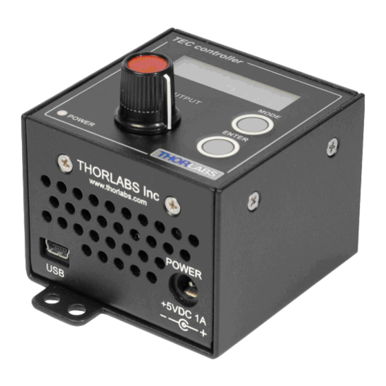
T-Cube Laser Diode Driver Chapter 4: Standalone Operation Chapter 4 Standalone Operation Control Panel Buttons and Indicators Figure 9 Panel Controllers and Indicators MAIN Display - Shows the Temperature Set Point applied to the TEC element. OUTPUT Potentiometer - Used to navigate the setup menus and to adjust parameter settings. MODE Button - Toggles between the Setup menu (refer to section 4.3) and the Monitor mode. -
Page 17: Setup Menu Overview
T-Cube Laser Diode Driver Chapter 4: Standalone Operation When the TEC current is enabled, pressing the Enter button disables the TEC current and the display will again flash the set temperature. The set temperature can be changed by rotating the OUTPUT Knob while in the Monitor Mode. If the TEC current is enabled, the display will temporarily switch to show the current set temperature and allow you to adjust it. -
Page 18: Selecting Display Value
T-Cube Laser Diode Driver Chapter 4: Standalone Operation 4.3.2 Selecting Display Value The display menu allows you to change the information displayed when the TEC element is enabled. Press the MODE button to enter the SETUP menu. Scroll using the OUTPUT knob to select the diSP menu item. Press the ENTER button to enter the Display menu. -
Page 19: Setting The Sensor Type
4.3.4 Setting the TEC Current Limit “Cur L” The temperature Controller TTC001 delivers a maximum TEC current of 1 A. The TEC current limit can be set through the “Cur L” menu. Press the Mode button to enter the Setup Menu. -
Page 20: Adjust The Temperature Control Loop
Increasing this value will speed up the heating or cooling of the TTC001 and decrease the time for the actual temperature to reach the set temperature. However, increasing this value also increases the amplitude and the number of overshoots and could make the system unstable if adjusted too high. -
Page 21: Setting The Display Brightness
4.3.8 Storing and Recalling Control Parameters The TTC001 allows you to store up to 5 sets of control parameters. Once you have selected the desired sensor type set the temperature range and current limit and optimize the control parameters. Select the “Pid” from the Setup menu. -
Page 22: Analog Control Of The Temperature
T-Cube Laser Diode Driver Chapter 4: Standalone Operation 4.3.9 Analog Control of the Temperature A zero to 5V analog input can be connected to the TUNE IN connector on the rear panel. It can then be used either to adjust the set temperature, allowing the PID loop to maintain the desired temperature, or to control directly the current output of the controller. - Page 23 6. Apply an analog voltage to jack "TUNE IN" at the rear panel of the Temperature Controller TTC001. Note: only slow variations of the temperature set value (<< 1 Hz) are possible via the analog control input "TUNE IN".
- Page 24 °C or °F. Enable the Temperature Controller TTC001 by pressing the Enter button. With the output switched on, the display stops blinking. During operation you can chose to display "t ACt", "Curr", or "dEltA" by selecting from the "diSP" menu at any time. "t ACt"...
-
Page 25: Chapter 5 Pc Operation
This tutorial shows how the Kinesis application provides all of the functionality necessary to operate the hardware. Power up the hardware, and wait until the TTC001 has finished booting up, then run the Kinesis software - Start/All Programs/Thorlabs/Kinesis/Kinesis. The panel for the TEC Controller should appear as shown in Figure 10. The Jog buttons and the Adjust Control Knob can be used to adjust the Temperature Set Value. - Page 26 T-Cube Laser Diode Driver Chapter 5: PC Operation Figure 11 TTC001 TEC Controller Settings Panel 4. In the Sensor Type field, select the appropriate temperature sensor for your application. 5. In the Current Limit field, enter an appropriate current limit value.
-
Page 27: Chapter 6 Software Reference
Figure 12 TTC001 TEC Controller Software GUI Note The serial number of the TTC001 unit associated with the GUI panel is displayed in the top right-hand corner. This information should always be provided when requesting customer support. Temperature Setting Controls These controls are used to adjust and set the TEC element set point value. -
Page 28: Control Tab
T-Cube Laser Diode Driver Chapter 6: Software Reference 20kOhm Thermistor 200kOhm Thermistor TSet Jog Step - the maximum current limit of the laser source. Due to individual variations between laser diodes, this value will differ from unit to unit. Loop Prop – The current value of the ‘Proportional’ parameter of the PID loop. Loop Int –... -
Page 29: Advanced Tab
T-Cube Laser Diode Driver Chapter 6: Software Reference 6.2.2 Advanced Tab Figure 14 Advanced Tab Sensor Type – the type of TEC element associated with the controller: If Transducer is selected, the Main Display shows values in degrees centigrade. If 20 KOhm Thermistor is selected, the Main Display shows values in kOhms. If 200 KOhm Thermistor is selected, the Main Display shows values in kOhms. -
Page 30: Chapter 7 Connector Pinout Details
The TEC OUTPUT connector on the rear panel provides connection to the Laser Diode Mount or other device. If Laser Diode Mounts by Thorlabs are used, connect the "TEC OUTPUT" of the TTC001 to the 9-pin plug "TEC DRIVER" of the Laser Diode Mount, using the provided shielded cable CAB420-15. -
Page 31: Chapter 8 Maintenance
The equipment contains no user serviceable parts. There is a risk of electrical shock if the equipment is operated with the covers removed. Only personnel authorized by Thorlabs Ltd and trained in the maintenance of this equipment should remove its covers or attempt any repairs or adjustments. -
Page 32: Chapter 9 Specifications And Associated Parts
T-Cube Laser Diode Driver Chapter 9: Specifications and Associated Parts Chapter 9 Specifications and Associated Parts General Specifications Parameter Value Temperature Sensor Type of Sensor Thermistor, AD590, AD592 Thermistor Sensing Current (TH 20 kΩ / 200 kΩ): 100 µA/10 µA AD590 / AD592: -45 to 125 °C Control Range: Thermistor 20 kΩ:10 Ω... - Page 33 ±1 A Temperature IC Sensor AD590 10k Thermistor TH10K Shielded cable to connect the CAB420-15 temperature controller to a Thorlabs' Laser Diode Mount 3-Channel K-Cube Controller Hub with KCH301 Power Supply 6-Channel K-Cube Controller Hub with KCH601 Power Supply TE-Cooled Mount For 5.6 mm Lasers...
-
Page 34: Chapter 10 Certifications And Compliance
T-Cube Laser Diode Driver Chapter 10: Certifications and Compliance Chapter 10 Certifications and Compliance D.1 Declarations of Conformity D.1.1 For Customers in Europe This equipment has been tested and found to comply with the EC Directives 89/336/EEC ‘EMC Directive’ and 73/23/EEC ‘Low Voltage Directive’... -
Page 35: Chapter 11 Thorlabs Worldwide Contacts
T-Cube Laser Diode Driver Chapter 11: Thorlabs Worldwide Contacts Chapter 11 Thorlabs Worldwide Contacts For technical support or sales inquiries, please visit us at for our most up-to-date www.thorlabs.com/contact contact information. USA, Canada, and South America UK and Ireland Thorlabs, Inc. - Page 36 www.thorlabs.com...
Need help?
Do you have a question about the TTC001 and is the answer not in the manual?
Questions and answers