Table of Contents
Advertisement
Quick Links
Advertisement
Table of Contents

Related Manuals for THORLABS TSC001


Summary of Contents for THORLABS TSC001
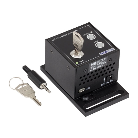
- Page 1 TSC001 T-Cube Solenoid Controller User Guide...
-
Page 2: Table Of Contents
Contents Chapter 1 Safety ..................... 4 1.1 Safety Information .................. 4 1.2 General Warnings .................. 4 Chapter 2 Overview and Setup ..............5 2.1 Introduction ..................... 5 2.2 T-Cube Controller Hub ................6 2.3 APT PC Software Overview ..............7 2.3.1 Introduction ...................... - Page 3 Appendix A Rear Panel Connector Pinout Details ........33 Appendix B Preventive Maintenance ............34 Appendix C Specifications and Associated Parts ........35 Appendix D Motor Control Method Summary ........... 36 Appendix E Regulatory ................37 Appendix F Thorlabs Worldwide Contacts ..........39...
-
Page 4: Chapter 1 Safety
Chapter 1 Safety 1.1 Safety Information For the continuing safety of the operators of this equipment, and the protection of the equipment itself, the operator should take note of the Warnings, Cautions and Notes throughout this handbook and, where visible, on the product itself. The following safety symbols may be used throughout the handbook and on the equipment itself. -
Page 5: Chapter 2 Overview And Setup
Chapter 2 Overview and Setup 2.1 Introduction The T-Cube Solenoid Controller (TSC001) is a new very compact single channel controller for easy manual and automated control of solenoid operated shutters, and other such devices. Designed to operate 15V solenoid actuated devices, this mini controller is fully featured, possessing an embedded DSP processor to provide a multitude of flexible operating modes. -
Page 6: T-Cube Controller Hub
For power, a compact multi-way power supply unit (TPS008) is available from Thorlabs allowing up to 8 T-Cube Drivers to be powered from a single mains outlet. This power supply unit is also designed to take up minimal space and can be mounted to the optical table in close proximity to the driver units, connected via short power leads. -
Page 7: Apt Pc Software Overview
2.3 APT PC Software Overview 2.3.1 Introduction As a member of the APT range of controllers, the TSC001 Solenoid Driver T-Cube shares many of the associated software benefits. This includes USB connectivity (allowing multiple units to be used together on a single PC), fully featured Graphical User Interface (GUI) panels, and extensive software function libraries for custom application development. -
Page 8: Aptuser Utility
Chapter 2 2.3.2 APTUser Utility The APTUser application allows the user to interact with a number of APT hardware control units connected to the host PC. This program displays multiple graphical instrument panels to allow multiple APT units to be controlled simultaneously. All basic operating parameters can be altered and, similarly, all operations (such as manual or automatic solenoid operation) can be initiated. -
Page 9: Apt Config Utility
T-Cube Solenoid Controller 2.3.3 APT Config Utility There are many system parameters and configuration settings associated with the operation of the APT Server. Most can be directly accessed using the various graphical panels, however there are several system wide settings that can be made 'off-line' before running the APT software. -
Page 10: Apt Server (Activex Controls)
Chapter 2 2.3.4 APT Server (ActiveX Controls) ActiveX Controls are re-usable compiled software components that supply both a graphical user interface and a programmable interface. Many such Controls are available for Windows applications development, providing a large range of re-usable functionality. -
Page 11: Software Upgrades
APT controller. This CD contains a complete range of tutorial samples and coding hints and tips, together with handbooks for all the APT controllers. 2.3.5 Software Upgrades Thorlabs operate a policy of continuous product development and may issue software upgrades as necessary. -
Page 12: Chapter 3 Getting Started
If you experience any problems when installing software, contact Thorlabs on +44 (0)1353 654440 and ask for Technical Support. DO NOT CONNECT THE CONTROLLER TO YOUR PC YET 1) Go to Services/Downloads at www.thorlabs.com and download the software. -
Page 13: Mechanical Installation
2.2. for further details. Full instructions on the fitting and use of the controller hub are contained in handbook ha0146 T-Cube Controller Hub, available from www.thorlabs.com. Caution When siting the unit, it should be positioned so as not to impede the operation of the control panel buttons. -
Page 14: Removing The Baseplate
Chapter 3 3.2.3 Removing the Baseplate The baseplate must be removed before the rubber feet (supplied) can be fitted, or the unit is connected to the USB controller hub.. Detail A Detail B Baseplate attachment screws Baseplate removed and rubber feet fitted Fig. -
Page 15: Electrical Installation
The TCH002 USB Controller Hub provides power distribution for up to six T-Cubes, and requires only a single power connection (from a separate supply unit TPS006 supplied by Thorlabs). Further details are contained in handbook ha0146T T-Cube Controller Hub, available from www.thorlabs.com. -
Page 16: Connecting To A Standalone Power Supply
The unit must be connected only to a DC supply of the rating detailed in Section 3.3.1. Connection to a supply of a different rating may cause damage to the unit and could result in injury to the operator. Thorlabs offers a compact, multi-way power supply unit (TPS008), allowing up to eight T-Cube Controllers to be powered from a single mains outlet. -
Page 17: Connect The Hardware
Wait while Windows installs the drivers for the new hardware - see the Getting Started guide for more information. 9) Run the APTUser utility Start/All Programs/Thorlabs/APT/APT User. 10) Your T-Cube Solenoid Controller is now ready for use. -
Page 18: Using An External Trigger
Below serial number 85810830: the ‘TRIG IN’ SMA defaults to logic HIGH when there is nothing driving this input, i.e. if the TSC001 unit is enabled, the shutter will open. Serial number 85810830 and above: the ‘TRIG IN’ SMA defaults to logic LOW, so the trigger is disabled when the external input is open circuit (disconnected), i.e. -
Page 19: Verifying Software Operation
T-Cube Solenoid Controller 3.5mm jackplug connected to a remote actuated (normally open) switch (e.g. an open door indicator), which must be closed before the unit can operate. Caution If the unit is being operated in a trigger mode, the interlock controls the output of the master unit in the normal way. - Page 20 Chapter 3 Follow the tutorial steps described in Chapter 4 for further verification of operation. Note The 'APT Config' utility can be used to set up simulated hardware configurations and place the APT Server into simulator mode. In this way it is possible to create any number and type of simulated (virtual) hardware units in order to emulate a set of real hardware.
-
Page 21: Chapter 4 Standalone Operation
Chapter 4 Standalone Operation 4.1 Introduction The T-Cube Solenoid Controller (TSC001) is a new very compact single channel controller for easy manual and automated control of solenoid operated shutters, and other such devices. Designed to operate 15V solenoid actuated devices, this mini controller is fully featured, possessing an embedded DSP processor to provide a multitude of flexible operating modes. -
Page 22: Using The Front Panel Buttons
Chapter 4 4.3 Using the Front Panel Buttons The buttons on the front of the unit are used to operate the solenoid-actuated device and to switch between operating modes as follows. 4.4 Mode Button Press and release to switch between modes. The ‘ENABLE LED flashes to indicate the selected mode as described below. - Page 23 T-Cube Solenoid Controller In all modes of operation, pressing the ENABLE button while the unit is “enabled” will disable the solenoid. Caution The way in which the MODE setting is saved between power cycles differs between early and later models. Below serial number 85810830, the MODE setting (e.g.
-
Page 24: Operation From The Front Panel
The following brief tutorial guides the user through a typical series of operations. 4.6.1 Preparation 1) Connect a solenoid actuated device (e.g. a Thorlabs SH05 Shutter) to the ‘SOLENOID’ connector on the rear panel of the unit. 2) Connect the INTERLOCK jack plug - see Section 3.4.2. -
Page 25: Chapter 5 Pc Operation - Tutorial
PC based APT software. 5.1 Preparation 1) Connect a solenoid actuated device (e.g. a Thorlabs SH05 Shutter) to the ‘SOLENOID’ connector on the rear panel of the unit. 2) Connect the INTERLOCK jack plug - see Section 3.4.2.. -
Page 26: Setting Manual Mode
Chapter 5 1) Run the APT User program - Start/Programs/Thorlabs/APT/APT User. 2) The PC detectes the hardware connected to the USB bus and the GUI panel for the Solenoid Controller is displayed. For an explanation of the GUI panel - see Section 6.2. -
Page 27: Creating A Simulated Configuration Using Apt Config
To create a simulated configuration proceed as follows: 1) Run the APT Config utility - Start/All Programs/Thorlabs/APT/APT Config. 2) Click the 'Simulator Configuration' tab. Fig. 5.3 APT Configuration Utility - Simulator Configuration Tab... - Page 28 4) In the 'Simulator' field, check the ‘Enable Simulator Mode’ box. The name of the most recently used configuration file is displayed in the 'Current Configuration' window. 5) In the ‘Control Unit’ field, select ‘1 Ch Solenoid Controller T-Cube (TSC001)’. HA0145T Rev 13 Sept 2016...
-
Page 29: Introduction To Solenoid Controller Programming
T-Cube Solenoid Controller 6) In the ‘Enter 6 digit serial number’ field, enter the serial number of your T-Cube Solenoid Controller. Note Each physical APT hardware unit is factory programmed with a unique 8 digit serial number. In order to simulate a set of ‘real’ hardware the Config utility allows an 8 digit serial number to be associated with each simulated unit. -
Page 30: Chapter 6 Software Reference
Chapter 6 Software Reference 6.1 Introduction This chapter gives an explanation of the parameters and settings accessed from the APT software running on the PC. 6.2 GUI Panel The following screen shot shows the graphical user interface (GUI) displayed when accessing the Solenoid Controller T-Cube using the APTUser utility. - Page 31 T-Cube Solenoid Controller Mode - this button sets the operating mode of the unit as follows: Manual - In this mode, operation of the solenoid is via the front panel ‘Enable’ button, or by the ‘Output’ buttons on the GUI panel. Single - In this mode, the solenoid will open and close each time the front panel ‘Enable’...
-
Page 32: Settings Panel
Chapter 6 6.3 Settings Panel When the 'Settings' button on the GUI panel is clicked, the 'Settings' window is displayed. This panel allows operating parameters, e.g. On and OFF times, to be modified. Note that these parameters also have programmable equivalents accessible through the ActiveX methods and properties on this Control (refer to the Programming Guide in the APTServer helpfile for further details and to Section 2.3.4. -
Page 33: Appendix A Rear Panel Connector Pinout Details
Appendix A Rear Panel Connector Pinout Details A.1 Rear Panel SOLENOID Connector The ‘SOLENOID’ connector provides connection to the shutter, or other solenoid actuated device. The pin functions are detailed in Fig. A.1. Description Opto Anode (12V limited to 20mA) Shutter Coil 15V Pulse, 10V steady state (0.4A max) Shutter Coil Ground (When ON) Open CCT (When OFF) Opto Cathode Ground... -
Page 34: Appendix B Preventive Maintenance
The equipment contains no user servicable parts. There is a risk of electrical shock if the equipment is operated with the covers removed. Only personnel authorized by Thorlabs Ltd and trained in the maintenance of this equipment should remove its covers or attempt any repairs or adjustments. -
Page 35: Appendix C Specifications And Associated Parts
Appendix C Specifications and Associated Parts C.1 Specifications Parameter Value Timing Resolution 250µs Trigger Input/Output On/Off Times 100ms to 10s Maximum Repetition Rate Up to 10Hz Output Enable Key Switch and Interlock Jack Plug Operating Modes Manual User Controlled On/Off Single DSP Controlled Single On/Off Cycle Auto... -
Page 36: Appendix D Motor Control Method Summary
A brief summary of the methods and properties applicable to the TSC001 is given below,. For more detailed information and individual parameter descriptions, please see the on-line help file supplied with the APT server. -
Page 37: Appendix E Regulatory
T-Cube Solenoid Controller Appendix E Regulatory E.1 Declarations Of Conformity E.1.1 For Customers in Europe See Section E.3. E.1.2 For Customers In The USA This equipment has been tested and found to comply with the limits for a Class A digital device, persuant to part 15 of the FCC rules. - Page 38 • left over parts of units disassembled by the user (PCB's, housings etc.). If you wish to return a unit for waste recovery, please contact Thorlabs or your nearest dealer for further information. E.2.2 Waste treatment on your own responsibility If you do not return an "end of life"...
- Page 39 E.3 CE Certificate...
-
Page 40: Appendix F Thorlabs Worldwide Contacts
UK and Ireland Thorlabs, Inc. Thorlabs Ltd. sales@thorlabs.com sales.uk@thorlabs.com techsupport@thorlabs.com techsupport.uk@thorlabs.com Europe Scandinavia Thorlabs GmbH Thorlabs Sweden AB europe@thorlabs.com scandinavia@thorlabs.com France Brazil Thorlabs SAS Thorlabs Vendas de Fotônicos Ltda. sales.fr@thorlabs.com brasil@thorlabs.com Japan China Thorlabs Japan, Inc. Thorlabs China sales@thorlabs.jp chinasales@thorlabs.com...
Need help?
Do you have a question about the TSC001 and is the answer not in the manual?
Questions and answers