Table of Contents
Advertisement
Quick Links
Advertisement
Table of Contents

Subscribe to Our Youtube Channel
Related Manuals for THORLABS TLD001


Summary of Contents for THORLABS TLD001
- Page 1 TLD001 Laser Diode Driver Kinesis User Guide Original Instructions HA0184T...
-
Page 2: Table Of Contents
T-Cube Laser Diode Driver Contents Chaper 1 Overview ....................1 1.1 Introduction ..................1 1.2 Power Supply Options ............... 2 1.3 Kinesis Software Overview ............... 2 1.3.1 Introduction ..................... 2 1.3.2 Kinesis Server ..................3 1.3.3 Software Upgrades ................. 4 Chaper 2 Safety ...................... - Page 3 6.2.3 Photodiode Tab ................... 43 6.2.4 Advanced Tab ..................44 Appendices Appendix A Rear Panel Connector Pinout Details ........45 Appendix B Preventive Maintenance ............47 Appendix C Specifications ................48 Appendix D Regulatory ................49 Appendix E Thorlabs Worldwide Contacts ..........51...
-
Page 4: Overview
Chapter 1 Overview 1.1 Introduction The TLD001 T-cube is a versatile, high precision laser diode/LED driver, designed to drive a wide range of semiconductor laser diodes. It supports operating currents of up to 200 mA, a hig h compliance voltage of 8 Vol ts and both constant current and constant power operating modes. -
Page 5: Power Supply Options
1.2 Power Supply Options Thorlabs offers a compact, two-way power supply unit (TPS002), allowing up to two Laser Diode driver T-Cubes to be powered from a single mains outlet. As a further level of convenience when using these Controllers, Thorlabs also offers the 3-channel and 6-channel K-Cube Controller Hubs (KCH301 and KCH601). -
Page 6: Kinesis Server
HPVEE, Matlab, VB.NET, C#.NET and, via VBA, Microsoft Office applications such as Excel and Word. Consider the Control supplied for a TLD001 Laser Diode driver unit . This Control provides a complete user graphical instrument panel to allow the Laser... -
Page 7: Software Upgrades
This is available either by pressing the F1 key when running the Kinesis server, or via the Start menu, Start\Programs\Thorlabs\Kinesis\.Net API Help. 1.3.3 Software Upgrades Thorlabs operate a policy of continuous product development and may issue software upgrades as necessary. The latest software can be downloaded from the ‘services’ section of www.thorlabs.com. -
Page 8: Chaper 2 Safety
T-Cube Laser Diode Driver Chapter 2 Safety 2.1 Safety Information For the continuing safety of the operators of this equipment, and the protection of the equipment itself, the operator should take note of the Warnings, Cautions and Notes throughout this handbook and, where visible, on the product itself. The following safety symb ols may be used throughout the handbook and on the equipment itself. -
Page 9: Warnings Relating To Laser Safety
2.3 Warnings Relating To Laser Safety Warning In itself, this laser driver does not produce any laser radiation, and Thorlabs has no control over the rating of the laser diodes this product may be used to drive. It is the users responsibility to ensure that the appropriate protection is used, and that standard safety precautions observed. -
Page 10: Chaper 3 Getting Started
T-Cube Laser Diode Driver Chapter 3 Getting Started 3.1 Mechanical Installation 3.1.1 Environmental Conditions Warning Operation outside the foll owing environmental limits may ad versely affect operator safety. Location Indoor use only Maximum altitude 2000 m Temperature range C to 40 Maximum Humidity Less than 80% RH (non-condensing) at 31°C To ensure reliable operation the unit should not be e xposed to corrosive agents or... -
Page 11: Removing The Baseplate
Chapter 3 Getting Started 3.1.3 Removing the Baseplate In order to help mounting the unit to an optical table, a baseplate is provided with the unit. However, if the unit is required to be operated free-standing (for example on a bench), the baseplate can be removed and rubber feet fitted. -
Page 12: Rear Panel Connections Overview
MOD IN (SMA connector) – Modulation or analog control input, -10V to +10V - see Section 5.5. Note Thorlabs supply a variety of SMA to BNC and SMC to BNC adaptor and extension cables. Please see our catalog, or visit www.thorlabs.com for further details. 3.3 Power Supply Connection 3.3.1 Supply Voltage and Current Requirements... -
Page 13: Connection To A Standalone Power Supply
4) If the unit is to be used with a PC, connect the USB cable. Thorlabs offers a compact, two-way power supply unit (TPS002), allowing up to two Laser Diode driver T-Cubes to be powered from a single mains outlet. However, if an external supply is to be used, see Appendix A.1 for power supply connector pin out... -
Page 14: Configuring The Unit To The Laser Diode
The TLD001 has been designed to drive all the possible configurations but care is needed to ensure that the l aser diode is connected to the controller correctly. - Page 15 For these types of laser diode to be used with the TLD001 unit, one terminal of the laser diode and/or photodiode MUST BE grounded externally, ideally as close to the case as possible.
-
Page 16: Connecting The Photodiode With Bias
"dark current" in the opposite direction to the p hotocurrent. The normal operating mode for the TLD001 is photovoltaic (zero bias) mode. With reverse bias, a b attery is connected in series with the photodiode to hold the device in reverse bias. - Page 17 Chapter 3 Getting Started O/P Power (mW) 25°C 60°C limit Forward current (mA) Fig. 3.7 Laser Diode Power v Current Characteristics Fig. 3.7 shows a typical laser diode power v current be havior. At currents be low a certain ‘threshold current’, the laser diode produces very little optical power. Once a threshold current is exceeded, the output power starts increasing very rapidly.
-
Page 18: Photodiode Current (Ipd) Range
(e.g. min. 0.5mA, max 2.0mA) and sometimes the values may fall in different ranges. In other instances, for example when an external photodiode is used, the range may not be known. Even if the range is unknown, the TLD001 offers a quick and simple procedure to allow the correct range to be set. -
Page 19: Calibrating The Power Display
Chapter 3 Getting Started diode is set by a digital to analog converter (DAC). This DAC produces a voltage that the software can set to be between zero and a fixed reference voltage. When constant po wer mode is selected , a cl osed loop controller is set up that continuously reads the photocurrent and adjusts the laser power accordingly, so that the photocurrent is always equal to a “setpoint”... -
Page 20: Summary
T-Cube Laser Diode Driver 3.3.10 Summary 1) For the TLD001 unit to dri ve a la ser diode satisfactorily, the fol lowing pre- requisites must be met: •Either the anode or the cathode of the laser diode must be connected to ground. -
Page 21: Using The Safety Interlock And Key Switch
(pins 1 and 5) before the unit can be enabled. If the unit is used with a Thorlabs LM14S2, LDM21, LDM56 or LDM90 laser diode mount, the interlock connection is integral within the mount (cable CAB400 required). Alternatively, the contact can be controlled externally;... - Page 22 T-Cube Laser Diode Driver Caution The interlock lines can be pe rmanently shorted if no interlock function is required (see Fig. 3.9). This option should be used ONLY if there is no possible safety hazard associated with using the product. Page 19 17874-D03...
-
Page 23: Chaper 4 Standalone Operation
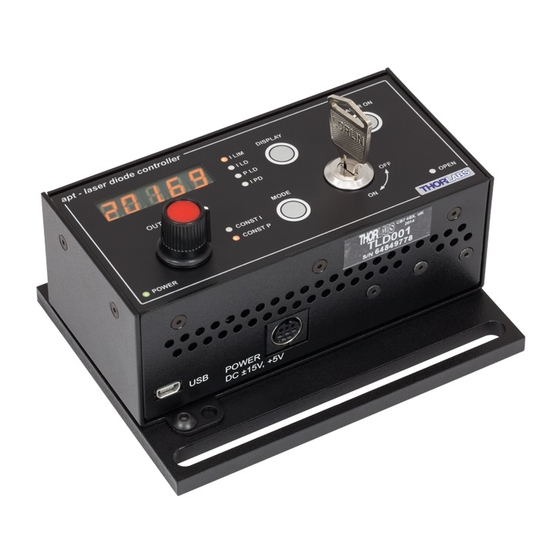
Chapter 4 Standalone Operation Chapter 4 Standalone Operation 4.1 Introduction The control panel of the TLD001 Laser Diode Controller T-Cube contains a 5 digit 7 Segment display, adjustment potentiometer, Mode, Display and Laser ON buttons, and a keyswitch. The following brief overview explains how the fron t panel controls can be used to perform a typical series of operations. -
Page 24: Set Up Preparation
3) Using cable CAB400, connect the diode mount to the TLD001 unit. 4) Connect the TLD001 to the power supply. 5) Attach the power meter to the diode mount. 6) Ensure that the KEYSWITCH on the TLD001 is set to OFF, then turn on the power to all units. CAB400 cable... -
Page 25: Front Panel Set Up Procedure
Chapter 4 Standalone Operation 4.4 Front Panel Set Up Procedure Before the laser diode driver can be used, it must be configured to operate with the specific laser diode it is intended to drive. The following section explains how the unit can be set up usin g the top panel buttons, and assumes th at the prep aration procedure detailed at Section 4.3. - Page 26 T-Cube Laser Diode Driver Max Laser Current This parameter allows the laser diode drive current limit to be set - se e Section 3.3.6. The maximum laser current adjustment can be done with the laser on or off. Press the MODE button to edit this parameter, or press the DISPLAY button to skip to the next parameter.
- Page 27 Chapter 4 Standalone Operation Photodiode Range This parameter al lows the correct pho todiode current amplifier range to be set - see Se ction 3.3.7. Note tha t in order to be able to do this, the laser must be turned on as otherwise the photocurrent will be zero.
- Page 28 T-Cube Laser Diode Driver Photodiode Gain Optimization This parameter allows the photodiode gain to be optimized - see Section 3.3.8. Optimization is performed automatically by the unit. Press the MODE bu tton to perform the optimization, or press the DISPLAY button to skip to the next parameter. When the MODE button is pressed, the display shows and a dot flashes to indicate that the optimization Pd oP...
- Page 29 The power meter shows a value which corresponds to the actual laser current. Turn the OUTPUT pot to set the TLD001 display to read the same numerical digits as the power meter (Ignore the decimal point and the ‘u’ sign for now, this will be set in the next step).
- Page 30 T-Cube Laser Diode Driver Display Brightness This parameter allows the display brightness to be adjusted. Press the MODE button to edit this parameter, or press the DISPLAY button to skip to the next parameter. When the MODE button is pressed, the display shows a value from 0 to 256, which represents the b rightness setting.
-
Page 31: Manual Operation Tutorial
‘OFF’, the unit must be re-enabled before it can operate. 4.6 Error Codes In order to protect the laser diode connected to the TLD001, the processor constantly monitors the power supply voltages. If any of the PSU voltages is out of tolerance, the processor disables the laser output, suspends any further action and displays an error message on the numerical display. -
Page 32: Mode Button Operation
T-Cube Laser Diode Driver 4.8 Mode Button Operation The TLD001 laser diode driver can b e operated in either C onstant Current or Constant Power mode. 4.8.1 Constant Current Mode (CONST I) As the name implies, this mode applies a constant drive current to the laser diode. -
Page 33: Chaper 5 Pc Operation - Tutorial
Caution The software must be installed BEFORE the driver is connected to your PC. If you experience any problems when installing software, contact Thorlabs on +44 (0)1353 654440 and ask for Technical Support. 1) Download the Kinesis software from www.thorlabs.com. -
Page 34: Set Up Preparation
4) Connect the TLD001 to the power supply. 5) Connect the power meter sensor to the diode mount. 6) Ensure that the KEYSWITCH on the TLD001 is set to OFF, then turn on the power to all units. 7) Connect the TLD001 unit to the control PC. -
Page 35: Set Up Via The Gui Panel
Section 5.3. has already been performed. Setting the Laser Diode Polarity As described in Section 3.3.4., the TLD001 laser diode driver supports all possible polarities of laser diode and the correct polarity must be set before a diode is powered 1) Make connections and run the KinesisKinesis software as described in Section 5.3. - Page 36 T-Cube Laser Diode Driver Adjusting the Laser Diode Drive Current Limit As previously explained in Section 3.3.6., the laser diode drive current limit must be set to ensure the diode is not overdriven. 5) Select the ‘Max Laser Current’ tab. Fig.
- Page 37 Chapter 5 PC Operation - Tutorial Note that the maximum laser current is adjustable in about 235 steps (clicks), with each step changing the current by about 0.7 mA. Setting the Photodiode Current Range Set the PD Current Range as follows: 10) Select the ‘Photo Diode’...
-
Page 38: Modulation Of The Laser Diode Output
T-Cube Laser Diode Driver Setting the Watts/Amps Calibration Factor The displayed power is d erived from the photodiode current, and the relationship between these parameters will differ between laser diodes. Therefore, the power display must be tuned to the diode being driven before the output power of the laser diode can be shown or adjusted accurately. - Page 39 Chapter 5 PC Operation - Tutorial 4) In the GUI Settings panel, select the ‘Advanced tab’, and set the Input Source as ‘External Signal’. Fig. 5.5 Laser Driver Settings - Advanced Tab 5) Click the ‘Persist Settings to Hardware’ box, then click OK. 6) Switch on the modulation source.
-
Page 40: Chaper 6 Software Reference
Kinesis software. Fig. 6.1 TLD001 Laser Diode Driver Software GUI Note. The serial number of th e TLD001 unit associa ted with th e GUI panel is displayed in the top right hand corner. This information should always be provided when requesting customer support. - Page 41 Laser Voltage display - shows the laser diode drive voltage. For grounded cathode laser diodes, the voltage is positive, for grounded anode diodes it is negative. Const P & Const I buttons - the TLD001 laser diode driver can be operated in either Constant Current or Constant Power mode.
-
Page 42: Settings Panel
T-Cube Laser Diode Driver Open Circuit LED - If the el e ctrical connection to the laser diode gets interrupted (i.e. the output goes open circuit) the internal protection circuit disables the laser output and turns on the Open Circuit LED. After the fault is cleared, the laser output can be re-enabled. -
Page 43: Control Tab
Chapter 6 Software Reference 6.2.1 Control Tab Fig. 6.1 Laser Driver Settings Panel - General Tab Display Mode Settings - this pa rameter sets th e 7-segment display on the control panel of the unit to show one of 4 operating parameters: Max Current limit (I ) in mA, Laser Diode Current (I... - Page 44 (AG) and cathode grounded (CG). This can be established from the laser diode data sheet and the devi ce should be connected to the D-type connector on the TLD001 accordingly - see Section 3.3.4. Select either Anode or Cathode , whichever is applicable.
-
Page 45: Max Current Tab
Chapter 6 Software Reference 6.2.2 Max Current Tab Fig. 6.2 Laser Driver Settings Panel - Max Laser Current Tab In order to protect against damage which could be caused by operating errors, the limit for the Laser Diode drive current should be set before diode is operated. Before any adjustments can be made to the settings on this tab, the ‘Enable Maximum Laser Current Adjustment’... -
Page 46: Photodiode Tab
T-Cube Laser Diode Driver 6.2.3 Photodiode Tab Fig. 6.3 Laser Driver Settings Panel - Photodiode Tab In order to ensure correct readings during operation, the Photo Diode operating range must be set before the laser diode is used. Note Before any adjustments can be made to the settings on this tab, the ‘Enable Photodiode TIA Range Adjustment’... -
Page 47: Advanced Tab
Chapter 6 Software Reference 6.2.4 Advanced Tab Fig. 6.4 Laser Driver Settings Panel - Advanced Tab In order to ensure correct readings during operation, the Photo Diode operating range must be set before the laser diode is Input Source Settings - the source(s) which control the output from the laser unit: If Software is selected, the u nit responds to software commands a nd the output to the laser is that se t using the SetPowerSetpoint method, or the ‘OUTPUT’... -
Page 48: Appendix A Rear Panel Connector Pinout Details
Appendix A Rear Panel Connector Pinout Details A.1 Power Connector Thorlabs recommends that the Laser Diode Driver T-Cube is operated with Thorlabs power supply TPS002, as it was spe cifically designed for use with this p roduct. However, to enable customers to use the cube in installations where a ±15V and 5V power is already available, the laser diode driver cube can be operated with a different external power supply, such as a bench or lab supply. - Page 49 Appendix A Rear Panel Connector Pinout Details A.2 Rear Panel LD OUT Connector. The ‘LD OUT’ connector exposes a number of electrical terminals used when connecting the laser diode or photo diode. It also exposes the Interlock connection, which must be closed before the laser diode can be turned on - see Section 3.3.11. The pin functions are detailed in Fig.
-
Page 50: Appendix B Preventive Maintenance
The equipment contains no user serviceable parts. There is a risk of electrical shock if the equipment is operated with the covers removed. Only personnel authorized by Thorlabs Ltd and trained in the maintenance of this eq uipment should remove its covers or attempt any repairs or adjustments. Maintenance is limited to safety testing and cleaning as described in the following sections. -
Page 51: Appendix C Specifications
TLD001 to LD Mount Connector Cable CAB400 SMA to BNC Converter Cable 6” CA2806 SMC to BNC Male Converter T4289 SMC to BNC Female Converter T4290 Please see www.thorlabs.com for our full range of laser diodes and diode mounts. Page 48 Rev A Nov 2017... -
Page 52: Appendix D Regulatory
T-Cube Laser Diode Driver Appendix D Regulatory D.1 Declarations Of Conformity D.1.1 For Customers in Europe See Section D.2. D.1.2 For Customers In The USA This equipment has bee n tested and found to comply wi th the limits for a Cl ass A digital device, persuant to part 15 of t he FCC rules. - Page 53 Appendix D Regulatory D.2 CE Certificate Page 50 Rev A Nov 2017...
-
Page 54: Appendix E Thorlabs Worldwide Contacts
Waste treatment is your own responsibility. "End of life" units must be returned to Thorlabs or handed to a company specializing in waste recovery. Do not dispose of the unit in a litter bin or at a public waste disposal site. - Page 55 www.thorlabs.com...
Need help?
Do you have a question about the TLD001 and is the answer not in the manual?
Questions and answers