Table of Contents
Advertisement
Advertisement
Table of Contents

Related Manuals for THORLABS MDT693B


Summary of Contents for THORLABS MDT693B
- Page 1 MDT693B and MDT694B Open-Loop Piezo Controllers User Guide...
-
Page 2: Table Of Contents
4.1. Setting AC Line Voltage and Fuses ......... 7 4.2. Changing Fuses .............. 7 4.3. List of Contents .............. 7 4.4. Initial Setup .............. 7 Chapter 5 Operation ................8 5.1. MDT693B Front Panel Overview ........ 8 5.2. MDT693B Back Panel Overview ........ 8 5.3. MDT694B Front Panel Overview ........ 9 5.4. MDT694B Rear Panel Overview ........ 9 5.5. Setting the Output Voltage Limit ......... 10 5.6. Using INT Adjustment Knob ......... 10 5.7. Using EXT Input BNC ............ 11 5.8. Master Scan Control (MDT693B Only) ...... 12 Chapter 6 Bandwidth Performance ..........14 ... - Page 3 Open-Loop Piezo Controllers Chapter 1: Warning Symbol Definitions 9.1. MDT693B Mechanical Drawing ........ 24 9.2. MDT694B Mechanical Drawing ........ 24 Chapter 10 Troubleshooting ............. 25 Chapter 11 Warranty ................26 Chapter 12 Regulatory ............... 27 Chapter 13 Certifications and Compliance........28 ...
-
Page 4: Chapter 1 Warning Symbol Definitions
Open-Loop Piezo Controllers Chapter 1 Warning Symbol Definitions Below is a list of warning symbols you may encounter in this manual or on your device. Symbol Description Direct Current Alternating Current Both Direct and Alternating Current Earth Ground Terminal Protective Conductor Terminal Frame or Chassis Terminal Equipotentiality On (Supply) -
Page 5: Chapter 2 Safety
MDT693B or MDT694B, the piezo can accumulate static charge over time due to varying storage temperature and/or mechanical loads. To safely discharge a piezo, connect it to the MDT693B or MDT694B and set the output voltage to 0 volts. - Page 6 Open-Loop Piezo Controllers With the exception of the mains fuses, there are no user-serviceable parts in this product. This device can only be returned when packed into the complete original packaging, including all foam packing inserts. If necessary, ask for a replacement package.
-
Page 7: Chapter 3 Description
USB voltage setting, the manual/USB control can be used for offset adjustments without having to re-adjust the external voltage source. The MDT693B and MDT694B include a voltage limit switch on the rear panel to select the operating voltage range and gain for the unit. Each unit is shipped with the voltage limit set for 0 –... -
Page 8: Chapter 4 Setup
Remove the existing fuse and install the appropriate fuse (600 mA for the MDT693B, 500 mA for the MDT694B). The replacement fuse must be a 5 mm x 20 mm, 250 VAC Type T Fuse (IEC 60127-2/III, low breaking capacity, slow blow). -
Page 9: Chapter 5 Operation
Open-Loop Piezo Controllers Chapter 5: Operation Chapter 5 Operation 5.1. MDT693B Front Panel Overview 7-Segment LED Master INT Master EX T Input 4 Digits Master Voltage Modulation Input EXT Input Adjust 0 – 10 V Modulation Input 0 – 10 V... -
Page 10: Mdt694B Front Panel Overview
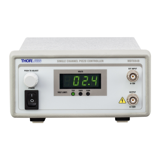
Open-Loop Piezo Controllers 5.3. MDT694B Front Panel Overview EXT Input 7-Segment LED Modulation Input 4 Digits 0 – 10 V INT Control Knob Voltage Adjustment Power Switch Turns Unit On and Off HV Output 1 Channel Output CAUTION: High Voltage 5.4. -
Page 11: Setting The Output Voltage Limit
5.5. Setting the Output Voltage Limit The MDT693B and MDT694B include a voltage limit switch on the rear panel that can be used to limit the maximum output voltage to 75 V, 100 V, or 150 V. The lower limit is intended for lower-drive-voltage piezos. Thorlabs ships the controllers to operate at the 75 V limit by default. -
Page 12: Using Ext Input Bnc
5.7. Using EXT Input BNC The EXT input on the MDT693B and MDT694B is designed to allow the user to modulate the output voltage or for use as feedback with positioning systems. Examples of connections for this input include D/A systems, strain gauges with support electronics, and function generators. -
Page 13: Master Scan Control (Mdt693B Only)
60 mA. A piezo acts like a capacitor; therefore the output current is a function of the change in voltage divided by the change in time. The MDT693B and MDT694B both have an output-current-limiting circuit to prevent damage to the unit, but the output sinusoid will be distorted. - Page 14 Open-Loop Piezo Controllers Master Scan Trim The SCAN TRIM adjusters scale the signals provided by the MASTER SCAN INT and MASTER SCAN EXT knobs over a range from 80% to 120% on a per-channel basis. This helps compensate for differences in reactance from one piezo to another.
-
Page 15: Chapter 6 Bandwidth Performance
Since the piezo can be modeled most accurately as a capacitor, the piezo will create a low-pass filter with the output impedance of the driver. For both the MDT693B and MDT694B, the output impedance is specified as 150 , 1 nF. Where, For example, consider connecting a piezo with a 1.6 F capacitance to the... - Page 16 Open-Loop Piezo Controllers Linear Ramp Signal ∆ ∆ ∆ ∆ Triangle Wave ∆ ∆ ∆ ∆ ∆ Sinusoid Wave Where For all equations above, TTN011225-D02, Rev C July 7, 2015...
-
Page 17: Chapter 7 Remote Communications
Windows and run CD_Started.exe. Follow the onscreen prompts to install the driver. After the driver is installed, attach the MDT693B or MDT694B to the PC and power it on. Your PC will then detect the new hardware and will prompt you when the installation is complete. - Page 18 Open-Loop Piezo Controllers terminator is a carriage return (CR), a line feed (LF) or any combination of a carriage return and line feed. See listing below. There are a few exceptions to this which are noted below, also noted are unique shortcut keys.
-
Page 19: Keywords (Commands And Queries)
Open-Loop Piezo Controllers Chapter 7: Remote Communications 7.3. Keywords (Commands and Queries) The following list shows all available commands and queries, and summarizes their functions for the MDT693B: Command Syntax Description Get Commands List the available commands. Returns the product header and... - Page 20 Sets the rotary controls mode. Set Rotary Mode rotarymode= (0 = Default, 1 = 10 turn pot, 2 = fine) All commands and queries are not case sensitive. The MDT693B will recognize MDT693A commands. TTN011225-D02, Rev C July 7, 2015...
- Page 21 Open-Loop Piezo Controllers Chapter 7: Remote Communications The following list shows all available commands and queries, and summarizes their functions for the MDT694B: Command Syntax Description Get Commands List the available commands. Returns the product header and firmware Product Information version Restore Default restore...
- Page 22 Open-Loop Piezo Controllers Get Serial Number serial? Returns the serial number. Returns compatibility mode Get Compatibility Mode (0 = disabled, 1 = enabled) Sets compatibility mode Set Compatibility Mode cm=n (0 = disable, 1 = enable) Returns the rotary controls mode. Get Rotary Mode rotarymode? (0 = default, 1 = 10 turn pot, 2 = fine)
-
Page 23: Chapter 8 Specifications
Communications USB 2.0 The MDT693B and MDT694B were tested without an external load connected (1 nF output impedance only). Adding a capacitive load, such as a piezo, will decrease the noise spec since the capacitance will create a low-pass filter with the output resistance. - Page 24 Rocker Switch Scan Trim Controls 4-Turn Potentiometer Remote Interface USB Type B Physical Specifications Display Type 7-Segment LED with 4 Digits Number of Displays MDT693B MDT694B Display Resolution 0.1 V Number of Channels MDT693B MDT694B Dimensions MDT693B 12.18" x 4.15" x 8.55" (309.4 x 105.5 x 217.1 MDT694B 6.05"...
-
Page 25: Chapter 9 Mechanical Drawings
Open-Loop Piezo Controllers Chapter 9: Mechanical Drawings Chapter 9 Mechanical Drawings 9.1. MDT693B Mechanical Drawing 12.18" (309.4 mm) 4.15" (105.5 mm) 8.55" (217.1 mm) 9.2. MDT694B Mechanical Drawing 6.05" 11.63" (153.6 mm) (295.4 mm) 2.88" 3.22" (73.2 mm) (81.8 mm) 12.11"... -
Page 26: Chapter 10 Troubleshooting
Make sure the unit is turned on prior to connecting the USB. I can’t connect to the Power off unit, remove AC cord, remove the MDT693B/MDT694B over the USB USB cable, reattach AC cord, power on unit port. and reattach the USB cable. -
Page 27: Chapter 11 Warranty
All returns must be accompanied by a Returned Material Authorization (RMA) number issued by Thorlabs. The customer is responsible for all costs incurred to ship the unit back to Thorlabs; in the case of warranty repairs, Thorlabs will cover the cost of shipment back to the customer. -
Page 28: Chapter 12 Regulatory
Waste Treatment is Your Own Responsibility If you do not return an “end of life” unit to Thorlabs, you must hand it to a company specialized in waste recovery. Do not dispose of the unit in a litter bin or at a public waste disposal site. -
Page 29: Chapter 13 Certifications And Compliance
Open-Loop Piezo Controllers Chapter 13: Certifications and Compliance Chapter 13 Certifications and Compliance Page 28 Rev C, July 7, 2015... - Page 30 Open-Loop Piezo Controllers TTN011225-D02, Rev C July 7, 2015...
-
Page 31: Chapter 14 Thorlabs Worldwide Contacts
Open-Loop Piezo Controllers Chapter 14: Thorlabs Worldwide Contacts Chapter 14 Thorlabs Worldwide Contacts USA, Canada, and South America UK and Ireland Thorlabs, Inc. Thorlabs Ltd. 56 Sparta Avenue 1 Saint Thomas Place, Ely Newton, NJ 07860 Cambridgeshire CB7 4EX Great Britain... - Page 32 www.thorlabs.com...
Need help?
Do you have a question about the MDT693B and is the answer not in the manual?
Questions and answers