
Summary of Contents for Vektek Guardian
- Page 1 VEKTEK, INC. 1334 East Sixth Avenue Emporia, KS 66801 18009920236 www.vektek.com PL‐3302 REV. P08 IAW ECN N/A PAGE 1 of 39 © Copyright 1986‐2010 by Vektek, Inc. ...
- Page 2 Vektek Guardian™ User’s guide Vektek, Inc. reserves the right to change specifications without notice in an ongoing product improvement process Vektek, Inc. 1334 East Sixth Avenue Emporia, KS 66801 1‐800‐992‐0236 vektek@vektek.com www.vektek.com P L 3 3 0 2 R e v . P 0 8 I A W N / A ...
-
Page 3: Table Of Contents
Vektek Guardian™ User’s guide ™ Table of Contents Quick Start Users Guide ....................7 MACHINE RECEIVER ..........................7 Powering the MACHINE RECEIVER ........................9 Pallet IDs................................9 INCYCLE ................................10 Outputs................................10 Pairing ..............................13 Installing Fixture Transmitter......................14 Mounting Considerations ..........................14 Overview..........................16 Using the MACHINE RECEIVER..................16 IN CYCLE..............................16 Idle................................17 Pallet Menu ............................18 Edit Pallet Name: .............................18 Store Pallet ...............................18 Delete Pallet ..............................19 Admin Menu ............................20 Add Pallet .................................20... - Page 4 Vektek Guardian™ User’s guide Maintenance ........................30 MACHINE RECEIVER Parts ........................31 FIXTURE TRANSMITTER Parts ......................32 Specifications........................33 Certification Information..................... 33 FCC Compliance ............................ 33 FCC Machine Receiver Antenna Information.....................33 Industry Canada (IC) Compliance ..................... 34 IC Machine Receiver Antenna Information ....................34 Troubleshooting ......................35 Appendix A: Discrete Setting Pallet Management Table ........37 MACHINE RECEIVER Discrete Setting Management Table ............37 Appendix B: Binary Setting Pallet Management Table ........38 MACHINE RECEIVER Binary Setting Management Table ............... 38 NOTES:..........................39 P L 3 3 0 2 ...
- Page 5 Vektek Guardian™ User’s guide Table of Figures Figure 1: Guardian™ Hardware........................7 Figure 2: MACHINE RECEIVER mounting dimensions ................... 7 Figure 3: MACHINE RECEIVER Wiring......................8 Figure 4: Start Up Screens........................... 11 Figure 5: Password Screen .......................... 12 Figure 6: Password Screen .......................... 13 Figure 7: Pairing Screen ..........................13 Figure 8: Pallet Added Screen ........................13 Figure 9: FIXTURE TRANSMITTER mounting dimensions................15 Figure 10: IN‐CYCLE Screen ......................... 16 Figure 11: IN‐CYCLE Screen w/ External Warning..................17 Figure 12: Main Screen ..........................17 Figure 13: Main Screen w/ External Warning ..................... 17 Figure 14: Edit Pallet Name Screen......................18 Figure 15: Store Pallet Screen ........................18 Figure 16: Delete Pallet Screen........................
- Page 6 Vektek Guardian™ User’s guide Figure 25: Input Mode Screen ........................22 Figure 26: Switch Type Screen ........................23 Figure 27: Channel Set Screen ........................23 Figure 28: Channel Adjust Screen ....................... 24 Figure 29: Faulted Pallets Menu ......................... 24 Figure 30: Stored Pallets Menu........................25 Figure 31: Pallet Info Menu......................... 25 Figure 32: Pallet Info Screen Description....................25 Figure 33 Signal Strength Chart ........................26 Figure 34 Link Quality Chart........................26 Figure 35: Machine Receiver Cable Wiring ....................27 Figure 36: Input/Output Specifications....................... 28 Figure 37: FIXTURE TRANSMITTER Wiring ....................29 Figure 38: Signal Logic Chart ........................29 Figure 39: FIXTURE TRANSMITTER w/ battery door removed..............30 P L 3 3 0 2 ...
-
Page 7: Quick Start Users Guide
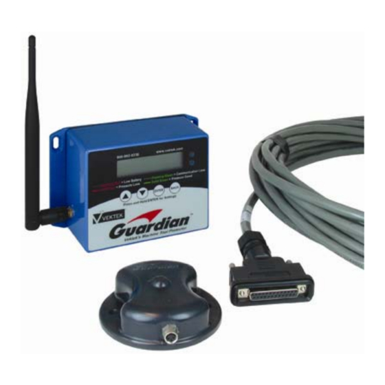
Vektek Guardian™ User’s guide Quick Start Users Guide Congratulations on purchasing the Vektek Guardian™! The following is a step by step quick start instruction guide to help you get the Guardian™ up and running with ease. The Guardian™ systems includes: Fixture Transmitter P/N 33‐0110‐09, Machine Receiver P/N 33‐ 0110‐08, Machine Receiver Cable and pairing tool (included with Machine Receiver). Require Vektek Pressure Switch P/N S7‐0750‐00 (sold separately) for operation in hydraulic applications. Figure 1: Guardian™ Hardware MACHINE RECEIVER Step 1: Mount the Receiver to the CNC machine in a location easily viewed by the operator. Below are dimensions for the mounting holes (Not to scale) NOTE: The MACHINE RECEIVER is a sealed unit but not designed to be mounted within the machine environment. Figure 2: MACHINE RECEIVER mounting dimensions P L 3 3 0 2 R e v . P 0 8 I A W N / A ... -
Page 8: Figure 3: Machine Receiver Wiring
Vektek Guardian™ User’s guide Step 2: Connect the cable to the Receiver via the Female DB25 connector. Route the cable to machine tool controls electrical enclosure. Find a entrance to the enclosure and determine the longest run cable needed. Cut the cable to length, and discard excess cable. Remove cable outer insulation as needed. Step 3: Unplug the MACHINE RECEIVER before continuing. Step 4: See the Basic MACHINE RECEIVER Wiring below to complete installation. Read and understand this section fully before attempting to wire the Guardian™ MACHINE RECEIVER. If any of the wiring information remains unclear after reading this section, please contact Vektek at 18009920236 Basic MACHINE RECIEVER Wiring This section will cover the basic information needed to hook up the MACHINE RECEIVER. Below is the wiring chart for the MACHINE RECEIVER. Figure 3: MACHINE RECEIVER Wiring P L 3 3 0 2 R e v . P 0 8 I A W N / A ... -
Page 9: Powering The Machine Receiver
Vektek Guardian™ User’s guide Powering the MACHINE RECEIVER There are 7 wires needed to power the unit. These are illustrated below. Provide +10‐24VDC to the following: Pin 19‐ BLUE/RED Pin 20‐ RED/GREEN NOTE: The wires can be tied together and hooked to the same source. A 1 amp fast acting fuse is recommended for protection of the MACHINE RECEIVER. Connect the following to 0 Volts: Pin 1‐ BLACK Pin 7‐ WHITE/BLACK Pin 13‐ RED/WHITE Pin 14‐ GREEN/WHITE Pin 25‐ GREEN/BLACK/WHITE Note: All five wires can be tied together and connected to the same source. If the installation prevents the use of all five wires, the unit will still operate with only one connected. Pallet IDs The number of Pallet IDs needed depends on the number of FIXTURE TRANSMITTERS to be used on the MACHINE RECEIVER being wired. For systems using 8 FIXTURE TRANSMITTERS or less, one Pallet ID will be needed per FIXTURE TRANSMITTER and the MACHINE RECEIVER Input Mode will be set as Discrete. For the Discrete or Binary setting, Pallet 1 is identified with the IN CYCLE input only. Example: A 2 pallet machine will use the pins illustrated below to identify pallets. P L 3 3 0 2 R e v . P 0 8 I A W N / A ... -
Page 10: Incycle
Vektek Guardian™ User’s guide IN CYCLE only is on the MACHINE REVCEIVER selects Pallet 1. When both IN CYCLE and PALLET ID 1 are provided, the MACHINE RECIEVER selects Pallet 2. The additional Pallet IDs do not need connected for this application. For systems using more than 8 FIXTURE TRANSMITTERS per MACHINE RECEIVER (Input Mode=Binary), please see the Pallet Management Table in Appendix A for the pins required to identify individual FIXTURE TRANSMITTERS. NOTE: The Input Common will need to be wired to complete the circuit for the pallet IDs.. All the inputs are illustrated below. For Machine Outputs providing 24 Volts: Connect the required Pallet IDs to Machine Outputs Connect both Pin 15 (BLUE/WHITE) and Pin 24 (RED/BLACK/WHITE) to 0 Volts For Machine Outputs providing 0 Volts: Connect the required Pallet IDs to Machine Outputs Connect both Pin 15 (BLUE/WHITE) and Pin 24 (RED/BLACK/WHITE) to the +DC source of the control. INCYCLE IN‐CYCLE will be connected identical to the Pallet IDs (i.e. Pallet IDs=Sourcing/IN‐ CYCLE=sourcing). Outputs The outputs of the MACHINE RECEIVER can provide a sourcing or sinking signal. For basic installations, the MAIN CONTACT will be the only output needed for machine shutdown. The additional outputs provide diagnostic information or signals for additional alarms. Basic hookup with the main contact only is shown below. All additional contacts used will provide the same type of signal (sourcing/sinking) as the Main Contact. NOTE: The Relay Common will need to be wired to complete the circuit for the Guardian ... -
Page 11: Figure 4: Start Up Screens
Vektek Guardian™ User’s guide Machine Inputs Requiring 24V: Connect the Guardian Outputs to Machine Inputs Connect Pin 15 (BLUE/WHITE) and Pin 24 (RED/BLACK/WHITE) to +DC source of the control. Machine Inputs Requiring 0 Volts: Connect the Guardian Outputs to Machine Inputs Connect Pin 15 (BLUE/WHITE) and Pin 24 (RED/BLACK/WHITE) to 0 Volts NOTE: The outputs provide a signal to the machine in the event of a fault on a fixture. It is the user’s responsibility to connect the outputs to the appropriate circuit for machine shutdown. System Setup Step 1: Once wired, plug in the MACHINE RECEIVER. It should power up automatically. The following two screens should appear momentarily with information about the MACHINE RECEIVER Channel MACHINE RECIEVER ID/ Software Serial Number Version (Hexadecimal Number) Figure 4: Start Up Screens Step 2: Press and Hold ENTER to access the Admin Menu. Step 2a: Use the and buttons to select the Settings option ... -
Page 12: Figure 5: Password Screen
Vektek Guardian™ User’s guide Figure 5: Password Screen Step 2b: Using the and buttons and ENTER to select the characters, input the password. To access the Settings and Diagnostics menus, the default password is 1234. If this password is an issue, please contact Vektek, Inc for assistance at 18009920236. Please have MACHINE RECEIVER version and ID number available for technical support. Step 2c: Using the and buttons, Press ENTER to select the Input Mode based on the number of pallets 8 or less‐ Discrete (See Pallet Management Table, Appendix A for identification pins) More than 8‐ Binary (See Pallet Management Table, Appendix B for identification pin combinations) Step 2d: Press the button (NEXT) to set the Switch Polarity. N/0 (Normally Open) ‐ Switch closes when safe operating pressure is reached. N/C (Normally Closed) ‐ Switch opens when safe operation pressure is reached. o NOTE: Vektek S7‐0750‐00 can be operated on either setting for multiple switch applications, see Settings section. Step 2e: Press the button (NEXT) to set the Channel ... -
Page 13: Pairing
Vektek Guardian™ User’s guide Figure 6: Password Screen Step 4: Use the Diagnostic functions to confirm communication with the machine control. See the Diagnostics section of the user’s guide. Pairing It is recommended pairing be completed before FIXTURE TRANSMITTERS are installed. Step 1: Press and hold ENTER to access the Admin menu. Select the ADD PALLET option using the and buttons and press ENTER. The MACHINE RECEIVER should now display: Figure 7: Pairing Screen Step 2: Using the pairing tool or other small magnet, sweep slowly over the Guardian™ logo molded in the FIXTURE TRANSMITTER housing. The red and blue LEDs should illuminate (may remain illuminated up to 30 seconds before pairing occurs) and the MACHINE RECEIVER will display: NOTE: The unit may require 2 passes with the magnet to pair, the first will turn on the FIXTURE TRANSMITTER; wait 5 seconds, and the next will begin the pairing process Figure 8: Pallet Added Screen Step 3(Optional): With the FIXTURE TRANSMITTER and MACHINE RECEIVER “paired,” each FIXTURE TRANSMITTER can be uniquely named. Step 3a: Using the and buttons, scroll through the paired FIXTURE TRANSMITTERS to find the pallet number of the FIXTURE TRANSMITTER and press ENTER. Step 3b: Using the ... -
Page 14: Installing Fixture Transmitter
Vektek Guardian™ User’s guide Step 3c: The name can be up to 9 alphanumeric characters (no punctuation). Using the and buttons, scroll through the characters and press ENTER to select the desired character as well as move to the next position. NOTE: Pressing ENTER moves the cursor forward one character, while pressing BACK moves the cursor back one character. Step 3d: When desired name is complete, press ENTER once to move to the next available character. Press and hold ENTER for 2 seconds to store and terminate the Edit Pallet Name and return to the main screen. Step 4: Record the pallet name in the “TRANSMITTER Name/Description” column of the Pallet Management Table included at the end of this manual, see Appendices. Step 5: Record the Serial number of the FIXTURE TRANSMITTER in the “TRANSMITTER Serial No.” column of the Pallet Management Table. The Serial number is located under the batteries or etched into the bottom of the housing next to the mounting holes. Step 6: Repeat Steps 1 through 5 to pair any additional FIXTURE TRANSMITTERS to the MACHINE RECEIVER. Step 7: The FIXTURE TRANSMITTERS are now ready to be installed on the fixtures. Installing Fixture Transmitter Mounting Considerations The FIXTURE TRANSMITTER does not require line of sight to communicate with the MACHINE RECEIVER; however, the FIXTURE TRANSMITTER will not operate properly if entirely enclosed. The highlighted red section of the FIXTURE TRASMITTER in the figure below shows the location of the antenna. A clear 360 degree view around the antenna will provide the best possible performance. Obstructions especially one over the top of the FIXTURE transmitter will decrease performance. See below for mounting suggestions. Step 1: Mount the transmitter using 2 ¼” or 2 6mm bolts oriented so the M8 connector is readily accessible to connect the switch cable. Below are mounting dimensions for the FIXTURE TRANSMITTER (Not to scale). P L 3 3 0 2 R e v . P 0 8 I A W N / A ... -
Page 15: Figure 9: Fixture Transmitter Mounting Dimensions
Vektek Guardian™ User’s guide Figure 9: FIXTURE TRANSMITTER mounting dimensions Step 2: Connect the switch cable to the transmitter. NOTE: For switches other than Vektek S7‐7500‐76 see “Transmitter Wiring Options.” WARNING: It is the customer’s responsibility to determine the minimum safe operating pressure for the system. Please test your system to ensure proper switch set pressure. Step 3: Set pressure switch to desired pressure. NOTE: Vektek suggests the pressure switch be set below the operating pressure of the fixture in order to account for small variations in pressure. Congratulations! You have just setup the Vektek Guardian™ system and are ready for operation. P L 3 3 0 2 R e v . P 0 8 I A W N / A ... -
Page 16: Overview
Vektek Guardian™ User’s guide Overview The Guardian™ is a wireless alerting system designed to automate pressure monitoring for hydraulic workholding. The Guardian™ System consists of two pieces, the MACHINE RECEIVER and the FIXTURE TRANSMITTER. The MACHINE RECEIVER features an LCD display to communicate with a human operator as well as a digital interface allowing the device to communicate with an external machine controller or PLC (Programmable Logic Control). The MACHINE RECEIVER is the hub of the Guardian System. The FIXTURE TRANSMITTER is a sealed, compact, low power device utilizing two “AA” batteries. The FIXTURE TRANSMITTER accepts an input from a non‐powered/dry contact sensing switch via an M8 connector and continuously reports the status of this switch over a data radio link. Vektek recommends pressure switch, P/N S7‐0750‐00, for hydraulic pressure monitoring. With Lithium AA batteries, the FIXTURE TRANSMITTER can operate for up to one year between battery changes, depending upon the duty cycle of the unit and the number of paired MACHINE RECEIVERS. Any FIXTURE TRANSMITTER can be used with up to 8 MACHINE RECEIVERS. Each FIXTURE TRANSMITTER must be “paired” with at least one MACHINE RECEIVER to operate. A FIXTURE TRANSMITTER can be paired and unpaired repeatedly with various MACHINE RECEIVERS. In a typical installation, a single MACHINE RECEIVER can be used with as many as 32 FIXTURE TRANSMITTERS. For applications requiring more than 32 FIXTURE TRANSMITTERS per MACHINE RECEIVER, please contact Vektek at 18009920236. Using the MACHINE RECEIVER IN CYCLE The machine tool selects a particular pallet through the digital inputs using a 5‐50 VDC signal to the MACHINE RECEIVER and asserting the IN‐CYCLE input. Once the MACHINE RECEIVER has the identification and the IN‐CYCLE input, it checks status of the appropriate FIXTURE TRANSMITTER and changes the status of the outputs according to the FIXTURE TRANSMITTER condition. Figure 10: IN‐CYCLE Screen When “in cycle,” the MACHINE RECEIVER display appears as shown above. The MACHINE RECEIVER shows the name and status of the selected FIXTURE TRANSMITTER switch on the display. The display will also alert the operator to a fault in the idle pallets but does not contain specific information about the faulted FIXTURE TRANSMITTER (see below). P L 3 3 0 2 R e v . P 0 8 I A W N / A ... -
Page 17: Idle
Vektek Guardian™ User’s guide Figure 11: IN‐CYCLE Screen w/ External Warning There are four possible status values that can be displayed for an active FIXTURE TRANSMITTER: OK– Pressure is good and battery is good. The OK status will also display a solid green light on the front of the MACHINE RECEIVER. FAIL– The pressure input is below set point. The FAIL status will cause a solid red light to be displayed on the MACHINE RECIEVER. BATT– Battery is Low. The BATT status will cause a flashing red light on the front of the MACHINE RECEIVER. COMM– The signal from FIXTURE TRANSMITTER is lost. The COMM status will cause the green light on the front of the MACHINE RECEIVER to flash. Idle When the MACHINE RECEIVER is not “In Cycle,” the status of each paired FIXTURE TRANSMITTER will scroll across the screen. While the MACHINE RECEIVER is idle, the user has the ability to use the 4 button interface on the unit. The idle screen is seen below. Figure 12: Main Screen The bottom line of the display contains the Pallet number, name, and status. The top line displays “Pallet Status—“or alerts the operator to a fault on an inactive FIXTURE TRANSMITTER (see below). Figure 13: Main Screen w/ External Warning There are five possible status values that can be displayed for a FIXTURE TRANSMITTER: OK– Pressure is good and battery is good. FAIL– The pressure input is below set point. BATT– Battery is Low. COMM– The signal from FIXTURE TRANSMITTER is lost. ... -
Page 18: Pallet Menu
Vektek Guardian™ User’s guide NOTE: While the MACHINE RECEIVER is not IN CYCLE, the LEDs on the front of the unit are not illuminated. Pallet Menu Pressing the ENTER button while the MACHINE RECIEVER is idle will access the Pallet Menu. The Pallet Menu allows the user to set the alphanumeric pallet name, to place a FIXTURE TRANSMITTER into “STORE” mode, or to delete a selected pallet. To scroll through the Pallet Menu options, press the and buttons. To select a menu function, press ENTER. To return to the main screen, press BACK. Edit Pallet Name: Figure 14: Edit Pallet Name Screen The pallet name can be up to 9 characters long (no punctuation). To enter the pallet name: 1. Using the and buttons, scroll through the alphabet in each letter position. a. ENTER stores the current character and moves forward one character, while BACK moves back one character. 2. When all 9 characters have been entered, pressing ENTER will exit this function. a. To enter a pallet name with less than 9 characters, press and hold the ENTER for 2 seconds to terminate data entry. ... -
Page 19: Delete Pallet
Vektek Guardian™ User’s guide 2. Using the and buttons, scroll to Store Pallet and press ENTER 3. Select the pallet from the list using the and buttons, and press ENTER. 4. The MACHINE RECEIVER will prompt PALLET # Stored and return to the main screen. To “wake up” a FIXTURE TRANSMITTER: 1. Pass the provided magnet over the Guardian™ logo on the FIXTURE TRANSMITTER. The FIXTURE TRANSMITTER LEDS should flash momentarily. 2. Check the status of the FIXTURE TRANSMITTER on the MACHINE RECEIVER to ensure the proper status is displayed. NOTE: FIXTURE TRANSMITTERS must remain in STORE mode for a minimum of 1 minute before they can be awakened. Delete Pallet Figure 16: Delete Pallet Screen The Delete Pallet option removes the pairing between the FIXTURE TRANSMITTER and the MACHINE RECEIVER so that they no longer communicate. To Delete a FIXTURE TRANSMITTER: 1. Press ENTER from the main screen 2. Use the ... -
Page 20: Admin Menu
Add Pallet Figure 18: Add Pallet Screen The Add Pallet option will put the MACHINE RECEIVER into pairing mode. It will remain in pairing mode until a new FIXTURE TRANSMITTER is paired or the function is cancelled by pressing BACK. To Pair a new FIXTURE TRANSMITTER: 1. Press and hold ENTER to access the Admin Menu. 2. Press ENTER to select Add Pallet 3. Pass the pairing tool or other available magnet over the Guardian™ logo on the FIXTURE TRANSMITTER. o NOTE: The unit may require 2 passes with the magnet to pair, one will turn on the FIXTURE TRANSMITTER; wait 5 seconds, and the next will begin the pairing process. 4. The red and blue LEDS on the FIXTURE TRANSMITTER should flash momentarily (up to 30 seconds depending on the MACHINE RECEIVER channel). 5. Once pairing is complete, the MACHINE RECEIVER will flash the screen below and return to idle operation. Figure 19: Pallet Added P L 3 3 0 2 R e v . P 0 8 I A W N / A ... -
Page 21: Diagnostics (Password Protected)
Vektek Guardian™ User’s guide Diagnostics (Password Protected) Figure 20: Diagnostics Menu The Diagnostics option allows the user to view the digital input status and also to test the individual outputs. The Diagnostics can be used to troubleshoot and verify an installation. There are 7 options under the Diagnostics menu and they are described below INP: (INPUT) The INP: or Input screen will show the status of all the inputs in the MACHINE RECEIVER. Inputs are labeled 1‐8 1‐7 are Pallet ID 1‐7 8 is the IN CYCLE input. Input Status 1=ON/0=OFF Figure 21: Input Status Screen MAIN/COMM/BATT/WARN/GREEN/RED RELAY Figure 22: Relay Status Screen For each individual output there is a sub menu to toggle the status. ENTER will close the contact and BACK will opens the contact. The and buttons allow the user to select the contact to toggle. The MACHINE RECEIVER only allows one relay at a time to close in Diagnostics. Once a relay is no longer on the display, it will default back to the open position. Upon exiting this menu, all relays will return to the open position. To Toggle Relay Position: ... -
Page 22: Settings (Password Protected)
Vektek Guardian™ User’s guide a. The one or zero in the upper right portion of the screen indicates the position of the relay (i.e. On=1, Off=0). b. If the or button is pressed while the relay is activated, it will deactivate the relay and move to the next screen. Output Status 1= ON/0= OFF Figure 23: Relay Position To Exit the Diagnostic Menu 1. Use the and buttons to return to the INP: Screen 2. Press BACK to Exit. Settings (Password Protected) Figure 24: Settings Menu The Settings menu allows the user to select the type (Normally Open/Closed) of the switch on each Pallet, set the input mode based on the number of pallets and to select the channel of the MACHINE RECEIVER and FIXTURE TRANSMITTERS. Input Mode: Figure 25: Input Mode Screen ... -
Page 23: Figure 26: Switch Type Screen
Vektek Guardian™ User’s guide 1. Press ENTER to change from Discrete to Binary 2. Press the or BACK button to save the setting. Press Switch: Figure 26: Switch Type Screen Normally Open (N/O) – Switch completes circuit when actuated. Wire Switches in series for multiple switch applications. Vektek pressure switch S7075000 can be wired in series for multiple pressure switch applications. Normally Closed (N/C) – Switch opens circuit when actuated. Wire multiple switches in parallel for proper operation. Vektek pressure switch S7075000 can be wired in parallel for multiple pressure switch applications. To change the switch type: 1. Press ENTER to change the switch type from N/C (Normally Closed) to N/O (Normally Open). NOTE: The Press Switch setting affects all the FIXTURE TRANSMITTER paired with the MACHINE RECEIVER. 2. Press the , or BACK button saves the setting. Channel: ... -
Page 24: Faulted Pallets
2. Use the and buttons to select the channel. a. If multiple MACHINE RECEIVERS are operating, it is recommended that each is on a separate channel. 3. Press ENTER to set the channel. NOTE: The FIXTURE TRANSMITTERS can operate on any of the 15 channels. To fix communication if a MACHINE RECEIVER channel changes: 1. Press and hold ENTER to reach the Admin Menu. 2. Press ENTER to select ADD PALLET. a. Disregard which Pallet # the MACHINE RECEIVER displays. 3. Pass the pairing tool or other available magnet over the Guardian Logo on the FIXTURE TRANSMITTTER. 4. The MACHINE RECEIVER will automatically exit pairing mode once the FIXTURE TRANSMITTER has updated the channel. Faulted Pallets Figure 29: Faulted Pallets Menu The Faulted Pallets option displays all the FIXTURE TRANSMITTERS with outstanding faults. To view the Faulted Pallets: 1. Press ENTER to access the Faulted Pallets option in the Admin Menu ... -
Page 25: Stored Pallets
Vektek Guardian™ User’s guide Stored Pallets Figure 30: Stored Pallets Menu The Stored Pallets menu displays any FIXTURE TRANSMITTERS currently in storage. To view the Stored Pallets: 1. Press Enter to access the Stored Pallet option. 2. Use the and buttons to view all the Stored Pallets. a. If no FIXTURE TRANSMITTERS are currently in storage mode, the list will read “<NO STORED PALLETS>.” Pallet Info Figure 31: Pallet Info Menu The Pallet Info option allows the user to see the addresses of the MACHINE RECEIVER and FIXTURE TRANSMITTER, MACHINE RECEIVER channel, switch position, and battery voltage of the FIXTURE TRANSMITTER. Below is a description of the information contained in the Pallet Info Screen. Below is an example of the information found on the Pallet Info screen. 2. 1. 6. Figure 32: Pallet Info Screen Description 7. 8. ... -
Page 26: Figure 33 Signal Strength Chart
Vektek Guardian™ User’s guide 7. Signal Strength 8. Link Quality Link Quality/Signal Strength Information The Link Quality number and Signal Strength number described the radio communication between the MACHINE RECEIVER and FIXTURE TRANSMITTER. The Charts below described the acceptable ranges of the values. Both values are independent, meaning signal strength can be good and Link Quality poor. Signal Strength Chart -100 Figure 33 Signal Strength Chart Link Quality Chart Figure 34 Link Quality Chart Rules for Link Quality and Signal Strength With good Signal Strength and poor Link Quality, interference may be present. With good Link Quality and poor Signal Strength, the range is too great or there is an object blocking the signal between the FIXTURE TRANSMITTER and MACHINE P L 3 3 0 2 R e v . P 0 8 I A W N / A ... -
Page 27: Machine Receiver Wiring
Vektek Guardian™ User’s guide RECEIVER. Try reorienting the FIXTURE TRANSMITTER or MACHINE RECEIVER antenna to improve signal. MACHINE RECEIVER Wiring The MACHINE RECEIVER uses a watertight DB25 25 pin connector with a prewired 25 conductor cable attached. The MACHINE RECEIVER is a sealed unit but is NOT designed to mount in a machining environment. Below is a description of the pin functions, wire color, and location on the connector. Figure 35: Machine Receiver Cable Wiring Pin Descriptions Below is a functional description of the various pins on the MACHINE RECEIVER +10‐24 Volts DC: 10‐24V DC power with a 1 amp fast acting fuse recommended (fuse not included) Relay Common: Wired appropriately for sourcing or sinking signal. Provides input to all output contacts Input Common: Wire appropriately for sourcing or sinking signal. Inputs rated at 5‐50 VDC. Pallet ID Pins (Input): Used to identify FIXTURE TRANSMITTER to be activated. Pallet IDs can be operated as DISCRETE or BINARY. Please see Settings Menu for complete description. P L 3 3 0 2 R e v . P 0 8 I A W N / A ... -
Page 28: Wiring Specifications
Vektek Guardian™ User’s guide In Cycle Pin (Input): Signals MACHINE RECIEVER to initiate communication and activate the identified FIXTURE TRANSMITTER, move output contacts according to condition of the FIXTURE TRANSMITTER. NOTE: No matter which Input Mode (Discrete or Binary), if the IN CYCLE input is given alone the MACHINE RECEVIER will default to Pallet 1. Main Contact (Output): Relay closes when MACHINE RECEIVER is given In‐cycle Input, and opens when In Cycle signal is lost or a fault is detected on active FIXTURE TRANSMITTER. Low Battery/Signal Loss Contact (Output): Appropriate relay closes in conjunction with Main Contact opening when associated fault is detected. Green/Red Status Light Contact (Output): The Green/Red Status Light Relays will mimic the status lights on the MACHINE RECEIVER. External Warning Contact (Output): Closes when a fault is detected among the idle FIXTURE TRANSMITTER. NOTE: NOT intended for machine shutdown. Relay only operates for all idle pallets. Does not identify faulted pallet only signals a general fault. OUTPUT NOTE: the Main Contact opens when a fault is detected; however, the other outputs close to signal an associated fault (Low Battery/Signal Loss/External Warning) has occurred. Wiring Specifications Below is a chart for the MACHINE RECEIVER I/O (Input/Output) ratings and position. Figure 36: Input/Output Specifications P L 3 3 0 2 R e v . P 0 8 I A W N / A ... -
Page 29: Fixture Transmitter M8 Wiring Description
Vektek Guardian™ User’s guide FIXTURE TRANSMITTER M8 Wiring Description The FIXTURE TRANSMITTER is designed to plug directly into Vektek pressure switch P/N S7‐ 7500‐00. If an alternate switch is to be used, the chart below provides a description of the pins on the FIXTURE TRANSMITTER. The FIXTURE TRANSMITTER cannot provide any power for inductive proximity switches or pressure transducers. Only nonpowered switches can be used with the Guardian system. Please consult Vektek Inc. (18009920236) for any additional switch concerns. Please have MACHINE RECEIVER version and ID number available for technical support. Figure 37: FIXTURE TRANSMITTER Wiring Signal Logic FAULT DETECTED MONITORING STARTS MONITORING STOPS IF FAULT CONDITION EXISITS Figure 38: Signal Logic Chart Additional Logic Information The Pallet ID inputs can be asserted at the same time or before the IN CYCLE input; however, if the Pallet ID is asserted before the IN CYCLE, it must remain on until the IN CYCLE input P L 3 3 0 2 R e v . P 0 8 I A W N / A ... -
Page 30: Maintenance
Vektek Guardian™ User’s guide is on. Once the FIXTURE TRANSMITTER has been identified and the IN CYCLE input is on, the Pallet ID inputs are no longer needed and the signals can remain or be removed without affecting the operation. As seen in the signal logic chart the MAIN CONTACT will close after the IN CYCLE input is on and communication has occurred with the FIXTURE TRANSMITTER. The MAIN CONTACT will open when the IN CYCLE input is removed. NOTE: If the IN CYCLE input is given with no Pallet IDs, the MACHINE RECIEVER will always default to Pallet 1 no matter the input mode (Discrete or Binary). Maintenance The MACHINE RECIEVER is a maintenance‐free unit. Vektek suggests to clean the face of the unit periodically with a mild cleaner (i.e. glass cleaner) and soft cloth to remove any foreign material. The FIXTURE TRANSMITTER requires periodic battery changes. The unit uses standard AA size batteries; however, high quality lithium batteries are recommended for maximum life. FIXTURE TRANSMITTER Battery Replacement Figure 39: FIXTURE TRANSMITTER w/ battery door removed To replace the batteries (shown above with battery door removed): 1. Remove FIXTURE TRANSMITTER from operating location. 2. Clean unit thoroughly, removing debris and liquid from near the screws and battery door to prevent contamination. 3. Remove four screws from rear battery door. 4. Remove battery door. 5. Remove and discard old battery door gasket. 6. Install new door gasket (Vektek P/N 39‐0550‐16). 7. Remove and replace batteries ensuring proper orientation of the batteries. 8. Reinstall battery door. DO NOT over tighten battery door screws. 9. Reinstall to operating location. Avoid over tightening mounting bolts. P L 3 3 0 2 R e v . P 0 8 I A W N / A ... -
Page 31: Machine Receiver Parts
Vektek Guardian™ User’s guide To reset FIXTURE TRANSMITTER: WARNING: This resets the FIXTURE TRANSMITTER removing all pairings. Once the reset is complete the FIXTURE TRANSMITTER will need paired to all associated MACHINE RECEIVERs. 1. Hold the pairing tool or other available magnet over Guardian logo for 15 seconds or until LEDS shut off. 2. Remove magnet immediately 3. Short pins 1 & 3 of the M8 connector on the FIXTURE TRANSMITTER after the LEDS re‐ illuminate. a. If pins 1&3 are not shorted while the LEDS are illuminated, the process will have to be repeated. 4. Once complete, the LEDS will remain dark. MACHINE RECEIVER Parts P L 3 3 0 2 R e v . P 0 8 I A W N / A ... -
Page 32: Fixture Transmitter Parts
Vektek Guardian™ User’s guide FIXTURE TRANSMITTER Parts P L 3 3 0 2 R e v . P 0 8 I A W N / A P a g e | 32 of 39 © Copyright 1986‐2010 by Vektek, Inc. -
Page 33: Specifications
Vektek Guardian™ User’s guide Specifications Guardian Specification Chart Power +10‐24 VDC Frequency 900 MHz Connection 1x DB25 Cable 50ft (included) Fixture Transmitter Capacity 32 Machine Receiver Inputs Number 8 P/N 33011008 Type Sourcing/Sinking Rating 5‐50 VDC Outputs Number Type ... -
Page 34: Industry Canada (Ic) Compliance
Vektek Guardian™ User’s guide Industry Canada (IC) Compliance Under Industry Canada regulations, this radio transmitter may only operate using an antenna of a type and maximum (or lesser) gain approved for the transmitter by Industry Canada. To reduce potential radio interference to other users, the antenna type and its gain should be so chosen that the equivalent isotropically radiated power (e.i.r.p.) is not more than that necessary for successful communication. The Guardian system MACHINE RECIEVER (P/N 33‐0110‐08) and FIXTURE TRANSMITTER (P/N 33‐0110‐09 comply with Industry Canada license‐exempt RSS standard(s). Operation is subject to the following two conditions: (1) this device may not cause interference, and (2) this device must accept any interference, including interference that may cause undesired operation of the device. IC Machine Receiver Antenna Information Antenna Type: Yagi The Guardian MACHINE RECEIVER has been designed to operate with yagi antennas having a maximum gain of 14 dB. Yagi antennas having a gain greater than 14 dB are strictly prohibited for use with this device. The required antenna impedance is 50 ohms. Antenna Type: Patch The Guardian MACHINE RECEIVER has been designed to operate with patch antennas having a maximum gain of 8 dB. Patch antennas having a gain greater than 8 dB are strictly prohibited for use with this device. The required antenna impedance is 50 ohms. Antenna Type: Omnidirectional The Guardian MACHINE RECEIVER has been designed to operate with omni‐directional antennas having a maximum gain of 5 dB. Omni‐directional antennas having a gain greater than 5 dB are strictly prohibited for use with this device. The required antenna impedance is 50 ohms. P L 3 3 0 2 R e v . P 0 8 I A W N / A ... -
Page 35: Troubleshooting
Vektek Guardian™ User’s guide Troubleshooting Symptom Cause Solution MACHINE RECIEVER does not 1. No power 1. Check ground power on. 2. Bad Ground connection 2. Check Fuse (if installed) 3. Check from pins 19 and 20 to ground for +10‐24VDC MACHINE RECEIVER does not 1. Not Paired 1. Re‐pair MACHINE communicate with FIXTURE 2. Out of Range RECEIVER and TRANSMITTER 3. FIXTURE FIXTURE TRANSMITTER in TRANSMITTER (See storage mode Pairing MENU) 4. Dead battery on ... - Page 36 2. Machine does not correct fault. wait long enough for 2. Allow at least 4 Main Contact to second for Main close. Contact to close. 3. Incorrect Fixture 3. Ensure Proper identified fixture has been 4. Main Contact not identified. wired correctly 4. Use Diagnostics 5. Logic of Guardian menu to toggle Main outputs not correct. Contact and check function of input to machine. 5. The Main Contact is Normally Closed and all other Contacts are Normally Open. 6. Check connection of Relay Common. Connect Relay Common to the voltage for the proper signal, 24V ...
-
Page 37: Appendix A: Discrete Setting Pallet Management Table
Vektek Guardian™ User’s guide Appendix A: Discrete Setting Pallet Management Table MACHINE RECEIVER Discrete Setting Management Table RECEIVER MACHINE RECEIVER Channel Pallet ID TRANSMITTER Pallet No. TRANSMITTER Name/Description Pins* Serial No. None 6 (ID 1) 5 (ID 2) 4 (ID 3) 3 (ID 4) 11 (ID 5) 10 (ID 6) 9 (ID 7) *NOTE: Pallet ID Pins above are for Discrete Input mode setting only ... -
Page 38: Appendix B: Binary Setting Pallet Management Table
Vektek Guardian™ User’s guide Appendix B: Binary Setting Pallet Management Table MACHINE RECEIVER Binary Setting Management Table RECEIVER MACHINE RECEIVER Channel Pallet ID TRANSMITTER Pallet No. TRANSMITTER Name/Description Pins* Serial No. None 4,5,6 3,5,6 3,4,6 3,4,5 3,4,5,6 11,6 11,5 11,5,6 11,4 11,4,6 11,4,5 11,4,5,6 11,3 11,3,6 11,3,5 11,3,5,6 11,3,4 11,3,4,6 11,3,4,5 11,3,4,5,6 NOTE: Pallet ID Pins above are for Binary Input mode setting only ... -
Page 39: Notes
Vektek Guardian™ User’s guide NOTES: P L 3 3 0 2 R e v . P 0 8 I A W N / A P a g e | 39 of 39 © Copyright 1986‐2010 by Vektek, Inc.
Need help?
Do you have a question about the Guardian and is the answer not in the manual?
Questions and answers