
Related Manuals for Keysight 16196A


Summary of Contents for Keysight 16196A
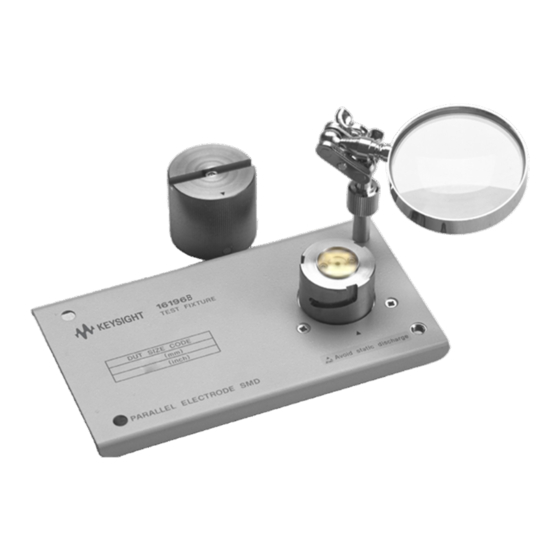
- Page 1 Keysight 16196A/B/C/D Parallel Electrode SMD Test Fixture Operation and Service Manual...
- Page 2 EULA. governed by United States and Declaration of Conformity Keysight shall be under no obligation international copyright laws. to update, revise or otherwise modify Trademark Acknowledgments Declarations of Conformity for this the Software.
-
Page 3: Table Of Contents
Incoming Inspection ............5 Connecting the 16196A/B/C/D to a Measuring Instrument ......10 2. - Page 4 Method Using Network Analyzer ..........74 Keysight 16196A/B/C/D Operation and Service Manual...
-
Page 5: Installation Guide
Keysight 16196A/B/C/D Parallel Electrode SMD Test Fixture Operation and Service Manual Installation Guide In this chapter, the procedures required from the time the 16196A/B/C/D Parallel Electrode SMD Test Fixture arrives until its use begins are described. Incoming Inspection Inspect the shipping container for damage. If the shipping container or... - Page 6 Installation Guide Incoming Inspection Figure 1-1 16196A/B/C/D Contents Keysight 16196A/B/C/D Parallel Electrode SMD Test Fixture...
- Page 7 16196B Package Contents Keysight Part Description Number 16196B Parallel Electrode SMD Test Fixture 16196-60212 Insulator Assembly 0.85 16196-60213 Insulator Assembly 0.75 Insulator Assembly 0.68 16196-60214 16196-29002 Open Plate 16196-29027 Short Plate 16196-24004 Push Ring Keysight 16196A/B/C/D Parallel Electrode SMD Test Fixture...
- Page 8 2. The Open Plate and Short Plate are packed in a single case and shipped. Refer to “Maintenance Kit” on page 67 for replaceable part. 3. Furnished with Option 710. 4. The manual is furnished only Option ABA is ordered. Keysight 16196A/B/C/D Parallel Electrode SMD Test Fixture...
- Page 9 3. The part number is different from that of the replacement part. When you order it for user maintenance, refer to Table 6-1 on page 4. Furnished with Option 710. 5. The manual is furnished only Option ABA is ordered. Keysight 16196A/B/C/D Parallel Electrode SMD Test Fixture...
-
Page 10: Connecting The 16196A/B/C/D To A Measuring Instrument
To connect the 16196A/B/C/D Test Fixture to a measuring instrument, it is necessary to use an adapter that fits the measuring instrument. The 16196A/B/C/D Test Fixture is suitable for use with a high frequency LCR Meter or Impedance Analyzer. Table 1-5 lists the appropriate combination of measuring instrument and adapter. - Page 11 Step 3. Turn the adapter's 7-mm connector counterclockwise, connecting the bottom of the test fixture with the connector. To make a firm connection with the test fixture, use the torque wrench (size: 3/4 inch, torque: 12 lb-in, Keysight part number: 8710-1766) to fasten the adapter's 7-mm connector. Figure 1-2...
- Page 12 Installation Guide Connecting the 16196A/B/C/D to a Measuring Instrument Keysight 16196A/B/C/D Parallel Electrode SMD Test Fixture...
-
Page 13: Product Overview
Operation and Service Manual Product Overview Product Overview The 16196A, 16196B, 16196C, and 16196D are test fixtures for measuring chip components. They enable chip type capacitors, inductors and other components to be measured with high precision and measurement repeatability. The 16196A/B/C/D also is compatible with measuring frequencies up to 3GHz. - Page 14 After passing through the DUT (Device Under Test), the current flows to the outer conductor via the cap electrode and returns to the outer conductor of the 7-mm connector. Through this structure, the ideal shield structure is formed. Keysight 16196A/B/C/D Parallel Electrode SMD Test Fixture...
-
Page 15: Functions
Enlarges the DUT and the insulator hole area. Magnifying Glass 1. Furnished with Option 710. 2. The magnifying glass is packed separately from the 16196A/B/C/D body. Connect Figure 2-3 it as shown in Keysight 16196A/B/C/D Parallel Electrode SMD Test Fixture... -
Page 16: Names Of Accessories And Functions
Supplementary tool used when removing DUTs. Cleaning Rod Cleans the electrodes. Wrench For removing hex nuts. Used to handle the open plate, short plate, and Tweezers DUTs, etc. 1. Furnished with Option 710. Keysight 16196A/B/C/D Parallel Electrode SMD Test Fixture... - Page 17 Product Overview Insulator Assembly In order to handle DUTs with differing shapes, the 16196A and 16196B each come with 3 types of insulator assembly, the 16196C comes with 1 insulator assembly, and the 16196D comes with two types of insulator assembly. Each of these insulator assemblies has little marks engraved in them to enable identification of each model and hole diameter.
- Page 18 Product Overview Product Overview Keysight 16196A/B/C/D Parallel Electrode SMD Test Fixture...
-
Page 19: Operation
Operation and Service Manual Operation This chapter describes preparations and fixture compensation when using the 16196A/B/C/D to take measurements as well as DUT connection and measuring methods. Flow of Measurements Follow the steps below when performing measurements of DUTs with the 16196A/B/C/D. -
Page 20: Selecting And Changing The Insulator Assembly
To take accurate and repeatable measurements, it is necessary for the DUT to be placed in the DUT insertion hole and be stable. For that reason, the 16196A and 16196B each are provided with 3 types of insulator assembly which have DUT insertion holes with different diameters (the 16196C has only one type of insulator assembly, and the 16196D has two types of insulator assembly). - Page 21 If the gap between the DUT and the insulator is large, the measurement accuracy and repeatability decrease. Select an insulator assembly that is appropriate for the shape of the DUT to be measured. Keysight 16196A/B/C/D Parallel Electrode SMD Test Fixture...
- Page 22 There is danger of the measuring precision and repeatability being adversely affected, and thus do not touch the lower electrode with your hands or damage it in any way. Keysight 16196A/B/C/D Parallel Electrode SMD Test Fixture...
- Page 23 Step 4. Connect the test fixture to the measuring instrument. Connect the test fixture to the instrument in accordance with “Connecting the 16196A/B/C/D to a Measuring Instrument” on page 10 in Chapter 1. Keysight 16196A/B/C/D Parallel Electrode SMD Test Fixture...
-
Page 24: Setting The Electrical Length
Setting the Electrical Length Set the electrical length in the measuring instrument. For the electrical length setting method, see the Operation Manual for the measuring instrument you are using. The electrical lengths for the 16196A/B/C/D are as shown below. Table 3-2 Electrical Length... -
Page 25: Performing Fixture Compensation
In order to perform more accurate measurements, before beginning the measurement procedure, it is necessary to compensate the fixture. For the 16196A/B/C/D, perform measurements of the data for open compensation and of the data for short compensation. The 16196A/B/C/D requires frequent wear checks to keep the best measurement accuracy. - Page 26 Step 3. Fit the cap in place with the mark toward the front, and turn it to the right until it is locked. Step 4. Take measurements of the data for open compensation in accordance with the Operation Manual for the measuring instrument you are using. Keysight 16196A/B/C/D Parallel Electrode SMD Test Fixture...
-
Page 27: Measuring Short Compensation Data
Figure 3-5 Setting the Short State Using the Short Plate Step 3. Fit the cap in place with the mark toward the front, and turn it to the right until it is locked. Keysight 16196A/B/C/D Parallel Electrode SMD Test Fixture... - Page 28 Step 4. Take measurements of the data for short compensation in accordance with the Operation Manual for the measuring instrument you are using. Residual inductance for the Short Plate is as follow. Model Residual Inductance [nH] 16196A 0.43 16196B 0.27 16196C 0.16 16196D 0.11 Keysight 16196A/B/C/D Parallel Electrode SMD Test Fixture...
-
Page 29: Connecting And Measuring Duts
Step 3. Fit the cap in place with the mark toward the front, and turn it to the right until it is locked. Step 4. Take measurements in accordance with the Operation Manual for the measuring instrument you are using. Keysight 16196A/B/C/D Parallel Electrode SMD Test Fixture... -
Page 30: Removing The Dut
Press the insulator assembly down using the push ring. When this is done, the lower electrode will push up the DUT and you will be able to remove it. Measurements can also be taken with the push ring placed as is on the insulator assembly. Keysight 16196A/B/C/D Parallel Electrode SMD Test Fixture... -
Page 31: User Maintenance
Keysight 16196A/B/C/D Parallel Electrode SMD Test Fixture Operation and Service Manual User Maintenance Overview The Necessity of User Maintenance The measurement performance of the fixture decreases slightly each time measurement is repeated. This is due to contamination of the contacting sections by solder, etc. -
Page 32: User Maintenance Flow
Parts Replacement When the wear Replacement of worn check is failed. parts Assembling Check After parts Measure Ls and Rs to replacement confirm that the fixture is assembled correctly. Keysight 16196A/B/C/D Parallel Electrode SMD Test Fixture... - Page 33 User Maintenance Overview Figure 4-1 Flowchart of User Maintenance Keysight 16196A/B/C/D Parallel Electrode SMD Test Fixture...
-
Page 34: Cleaning
• Lower Electrode (Figure 4-2 (3)) • Insulator Assembly recessed part (Figure 4-2 (4)) • Body side surfaces (Figure 4-2 (5)) • Short Plate • Open Plate Figure 4-2 Places to be Cleaned Keysight 16196A/B/C/D Parallel Electrode SMD Test Fixture... -
Page 35: Cleaning Methods
Figure 4-2 Open Plate, Short Plate Use the Cleaning Rod (Keysight parts number 5182-7586) for the cleaning.Use the white rubber part of the cleaning rod to remove dirt from all contacting surfaces of the above-mentioned parts. Be careful not to scratch or damage the parts when removing the dirt. - Page 36 (2)), Body Side Surfaces ( (5)) Figure 4-2 Figure 4-2 Wipe dirt off using a soft cloth, etc. When removing dirt, always be careful to clean so that the electrodes and insulator assembly are not damaged. Keysight 16196A/B/C/D Parallel Electrode SMD Test Fixture...
-
Page 37: Wear Check
20%. Accordingly, in order to measure both L and Q with a measurement accuracy of 20% or less, at least the error of L and R must be less than 2nH and 120m, respectively. While remembering that L and R Keysight 16196A/B/C/D Parallel Electrode SMD Test Fixture... - Page 38 Please enter the user limit values in the “Check Sheet” (Page Page 44). See “Check Sheet Fill-Out Example” on page 42 for an example of how this is done. Keysight 16196A/B/C/D Parallel Electrode SMD Test Fixture...
-
Page 39: Reference Value Acquisition
Step 1. Remove the cap and ensure that nothing is inserted into the fixture. Step 2. Clean the fixture’s upper and lower electrodes as described in “Cleaning” on page Step 3. Connect the fixture to the 7-mm connector. Keysight 16196A/B/C/D Parallel Electrode SMD Test Fixture... - Page 40 Step 5. Record the read values as the reference values in the “Check Sheet” (Page 44). Step 6. Calculate the upper limit value and the lower limit value from the previously set user limits and the reference values obtained here. Record these in the “Check Sheet”. Keysight 16196A/B/C/D Parallel Electrode SMD Test Fixture...
-
Page 41: Measuring Impedance Shift
“Acquisition Procedure (Short Plate Wear Check Reference Value)” on page Step 3. Enter the Rs and Ls measured values as pass-fail in the “Check Sheet” (Page 44). Step 4. If the result is unacceptable, replace the short plate. Keysight 16196A/B/C/D Parallel Electrode SMD Test Fixture... -
Page 42: Check Sheet
Oct./11/1999 800 MHz 345m Pass 9:35 360pH Pass Oct./12/1999 100 MHz 105m Pass 9:30 340pH Pass Oct./12/1999 800 MHz 355m Fail 9:35 320pH Pass 1. When the result is unacceptable, replace the part. Keysight 16196A/B/C/D Parallel Electrode SMD Test Fixture... -
Page 43: Electrode Wear Check
[a - b] [a + b] m m m m m m m m Table 4-6 Check History Date Frequency Measurement Measured Value Pass/Fail Parameter m m m m m m m m m Keysight 16196A/B/C/D Parallel Electrode SMD Test Fixture... -
Page 44: Short Plate Wear Check
[a - b] [a + b] m m m m m m m m Table 4-8 Check History Date Frequency Measurement Measured Value Pass/Fail Parameter m m m m m m m m m Keysight 16196A/B/C/D Parallel Electrode SMD Test Fixture... -
Page 45: Parts Replacement
For details, see “Maintenance Kit” on page Check Following Replacement Following replacement of parts, it is necessary to confirm that the fixture has been correctly assembled. Please conduct the “Assembling Check” on page Keysight 16196A/B/C/D Parallel Electrode SMD Test Fixture... -
Page 46: Assembling Check
Step 2. Clean the fixture’s upper and lower electrodes as described in “Cleaning” on page Step 3. Connect the fixture to the 7-mm connector. Step 4. Place the cap on the fixture body. Keysight 16196A/B/C/D Parallel Electrode SMD Test Fixture... - Page 47 If these are correctly attached but the results still remain outside the limit range, the fixture main body may be damaged. In this case, please contact a Keysight Technologies Sales or Service office. Step 8. Tighten the screw on top of the cap loosened in Step 5.
- Page 48 1GHz 120m 540m 300pH 100pH Table 4-13 Electrode Check and Limits (16196D) Parameter Frequency Limit (Absolute value) 100MHz 40m 250m 300pH 350pH 80m 810m 1GHz 300pH 200pH Keysight 16196A/B/C/D Parallel Electrode SMD Test Fixture...
-
Page 49: Short Plate Check
Step 2. Remove the cap and place the short plate with the protruding surface down on the insulator assembly. Step 3. Place the cap on the fixture body and fasten it. Step 4. Measure Rs and Ls at 100MHz and 1GHz in this condition. Keysight 16196A/B/C/D Parallel Electrode SMD Test Fixture... - Page 50 120m 570m 50pH 350pH Table 4-18 Short Plate Check and Limits (16196D) Parameter Frequency Limit (Absolute value) 30m 260m 100MHz 50pH 600pH 80m 860m 1GHz 0pH 350pH Keysight 16196A/B/C/D Parallel Electrode SMD Test Fixture...
-
Page 51: Specifications And Supplemental Performance Characteristics
Keysight 16196A/B/C/D Parallel Electrode SMD Test Fixture Operation and Service Manual Specifications and Supplemental Performance Characteristics This chapter provides specifications and supplemental performance characteristics of the 16196A/B/C/D test fixture. -
Page 52: Specifications
Weight 250g (nominal) Model (nominal) 16196A 26.2mm 16196B 26.9mm 16196C 27.1mm 16196D 27.3mm Safety Standards IEC 61010-1:2001 / EN 61010-1:2001 Canada: CAN/CSA C22.2 No. 1010.1-92 Installation/overvoltage category II Pollution degree 2 Indoor use Keysight 16196A/B/C/D Parallel Electrode SMD Test Fixture... -
Page 53: Supplemental Performance Characteristics
Specifications and Supplemental Performance Characteristics Supplemental Performance Characteristics Supplemental Performance Characteristics This section provides useful data on the 16196A/B/C/D. These supplemental performance characteristics should not be considered specifications. Additional Error Additional errors are calculated as follows. |Z| Measurement Additional error for Impedance Ze [%] is calculated by substituting the values in the table below into the following equation. - Page 54 Dx is the measured value of D and is calculated as follows. Dx = 2 × π × f × Csx × Rsx, where f: measurement signal frequency Csx: measured value of Cs Rsx: measured value of Rs. Figure 5-1 Additional Error for Impedance Keysight 16196A/B/C/D Parallel Electrode SMD Test Fixture...
- Page 55 The following table shows the factory default of loading weight on the DUT for each model. For the 16196D, the user can replace a part (washer) inside the cap to change it. For the 16196A/B/C, however the loading weight on the DUT cannot be changed.
- Page 56 [mm] into the following equation. G [gf] = 119 x (3.55 + t) - 420 If a washer with a thickness (t) of less than 1.0 mm is used, measurement may not be performed accurately. Keysight 16196A/B/C/D Parallel Electrode SMD Test Fixture...
- Page 57 0.2 Kgf-cm (0.2 in-lb). 8. Clean [7]. (See “User Maintenance”of the Chapter 4, “Cleaning.”) Be careful not to bolt inside parts out of the cap when detaching/attaching [1] and [2], because the spring [6] is powerful. Keysight 16196A/B/C/D Parallel Electrode SMD Test Fixture...
- Page 58 Specifications and Supplemental Performance Characteristics Supplemental Performance Characteristics Keysight 16196A/B/C/D Parallel Electrode SMD Test Fixture...
-
Page 59: Service
Keysight 16196A/B/C/D Parallel Electrode SMD Test Fixture Operation and Service Manual Service This chapter describes the proper maintenance of the fixture and parts replacement. Serial Number for Non-RoHS Test Fixture: 16196A: “MY43100001 – MY43200366”or “SG43100001 – SG43200366” 16196B: “MY43100001 – MY43200332”or “SG43100001 – SG43200332”... -
Page 60: Replaceable Parts
Technologies Sales/Service Office for repair or replacement. Shown are the support parts for RoHS and non-RoHS compliance 16196A/B/C/D Parallel Electrode SMD Test Fixture, DC to 3 GHz. All the listed items are changed at RoHS conversion. Due to limited availability of RoHS compliance station and technical difficulties in RoHS soldering, only parts and support level that do not require RoHS soldering are supported. -
Page 61: Block Assembly
Service Replaceable Parts Block Assembly Figure 6-1 Block Assembly Exploded View Keysight 16196A/B/C/D Parallel Electrode SMD Test Fixture... - Page 62 Ground Assembly Ground Assembly Lower Electrode Lower Electrode 16196-60111 16196-60111 (for 16196A) (for 16196A) 16196-60211 Lower Electrode 16196-60211 Lower Electrode (for 16196B) (for 16196B) 16196-60311 Lower Electrode 16196-60311 Lower Electrode (for 16196C) (for 16196C) Keysight 16196A/B/C/D Parallel Electrode SMD Test Fixture...
- Page 63 Plate 16196-00621 Plate (for 16196C) (for 16196C) 16196-00632 Plate 16196-00632 Plate (for 16196D) (for 16196D) Maintenance Kit consisting of 5 replaceable parts is available. Refer to “Maintenance Kit” on page 67 for details. Keysight 16196A/B/C/D Parallel Electrode SMD Test Fixture...
-
Page 64: Cap
Screw Mach M1.6 16196-24005 Stopper 16196-24005 Stopper 1460-2618 Spring 1460-2618 Spring 16196-23008 Upper Electrode 16196-23008 Upper Electrode Maintenance Kit including 5 replaceable parts is available. Refer to “Maintenance Kit” on page 67 for details. Keysight 16196A/B/C/D Parallel Electrode SMD Test Fixture... - Page 65 3050-2241 Washer 3050-2239 Washer 3050-2239 Washer 1460-2618 Spring 1460-2618 Spring 16196-23043 Upper Electrode 16196-23043 Upper Electrode Maintenance Kit including 5 replaceable parts is available. Refer to “Maintenance Kit” on page 67 for details. Keysight 16196A/B/C/D Parallel Electrode SMD Test Fixture...
-
Page 66: Other Parts
5182-7586 Cleaning Rod 5182-7586 Cleaning Rod 8710-0909 Wrench 1.5 mm 8710-0909 Wrench 1.5 mm 8710-2081 Tweezers 8710-2081 Tweezers 1540-0622 Case for OPEN 9300-2603 Case with Cap and SHORT plate 9282-0114 Cushion 16196-25614 Cushion Keysight 16196A/B/C/D Parallel Electrode SMD Test Fixture... -
Page 67: Maintenance Kit
Maintenance Kit Maintenance Kit The 16196U-maintenance kit is available to provide consumable products and replaceable parts for the 16196A/B/C/D. 16196U Maintenance Kit The 16196A/B/C/D common option and options for each model separately are available. Table 6-5 16196A/B/C Common Option Opt010... -
Page 68: Replacement Procedure
After replacing the respective parts, check the operation of the parts with reference to "Operation Check." To replace the insulator and upper electrode, the 1.5-mm hex wrench (Keysight Part No. 8710-0909), included with the fixture, is required. -
Page 69: Lower Electrode
Lower Electrode 1. Prepare the replacement center electrode. 2. Take out the 3 screws from the bottom of the fixture and take out the DUT insert. Figure 6-4 Removing the Bottom of the Fixture Keysight 16196A/B/C/D Parallel Electrode SMD Test Fixture... - Page 70 DUT’s bottom surface. 5. Insert the DUT insert in the bottom of the fixture so that the bottom screws settle into the holes in the bottom of the fixture. Keysight 16196A/B/C/D Parallel Electrode SMD Test Fixture...
-
Page 71: Insulator
Mounting the DUT Insert 6. Fasten the DUT insert to the bottom of the fixture using the screws. Insulator Replace the insulator with reference to “Selecting and Changing the Insulator Assembly” on page Keysight 16196A/B/C/D Parallel Electrode SMD Test Fixture... -
Page 72: Upper Electrode
4. Take the electrode out of the spring and insert the replacement electrode. 5. Push the electrode in from the bottom of the cap so that the top of the electrode protrudes out of the top of the cap. Figure 6-7 Electrode Replacement 1 Keysight 16196A/B/C/D Parallel Electrode SMD Test Fixture... - Page 73 In case of the 16196D, while holding the electrode, attach the washer and tighten the screw. The tightening torque is 0.2 Kgf-cm (0.2 in-lb). Figure 6-8 Electrode Replacement 2 Keysight 16196A/B/C/D Parallel Electrode SMD Test Fixture...
-
Page 74: Assembling Check
The assembly check methods with the network analyzer are explained in the following. The network analyzer can be used only for the assembling check. The network analyzer has no function to measure DUT with the 16196A/B/C/D. Method Using Network Analyzer Required Tools •... - Page 75 Step 5. Take Mag and Phase value readings at 100MHz and 1GHz and record the results. Check if the Mag and Phase values are within the typical value ranges shown in the following table. Table 6-10 Operation Check Typical Values (Open, common for 16196A/B/C/D) Parameter Frequency Typical Value (Absolute value) 0.2 ...
- Page 76 1GHz Table 6-14 Operation Check Typical Values (Short, 16196D) Parameter Frequency Typical Value (Absolute value) 100MHz 0.15 0 1GHz 0.40 0 Phase 100MHz 179º 180º Phase 1GHz 174º 180º Keysight 16196A/B/C/D Parallel Electrode SMD Test Fixture...
- Page 77 Cleaning Methods, Fill-Out Example, Functions, Cleaning identifications, Methods, installing, Places Requiring, Places Requiring Cleaning, Cleaning Rod Removing, 16196A Package Contents, Replaceable Parts, 16196B Package Contents, Selecting, 16196C Package Contents, Specifications, 16196D Package Contents, Functions, Keysight 16196A/B/C/D Operation and Service Manual...
- Page 78 16196B, Open Plate 16196C, 16196A Package Contents, 16196D, 16196B Package Contents, Performance Check 16196C Package Contents, Method Using Network Analyzer, 16196D Package Contents, Push Ring Cleaning Methods, 16196A Package Contents, Functions, 16196B Package Contents, Keysight 16196A/B/C/D Operation and Service Manual...
- Page 79 16196D Package Contents, Cleaning Methods, Functions, Places Requiring Cleaning, Replaceable Parts, Residual inductance, 33, 63 Short Compensation, Short Plate Check, Short Plate Wear Check Check Sheet, Reference Value Acquisition, Short Repeatability, Specifications, Supplemental Performance Characteristics, Keysight 16196A/B/C/D Operation and Service Manual...
- Page 80 Index Keysight 16196A/B/C/D Operation and Service Manual...
- Page 81 This information is subject to change without notice. © Keysight Technologies 1999-2020 Edition 6, January 2020 *16196-90040* 16196-90040 www.keysight.com...
Need help?
Do you have a question about the 16196A and is the answer not in the manual?
Questions and answers