Table of Contents
Advertisement
Quick Links
Advertisement
Table of Contents

Related Manuals for Keysight 16034H


Summary of Contents for Keysight 16034H
- Page 1 Keysight 16034H Test Fixture Operation Manual...
- Page 2 EULA. governed by United States and Declaration of Conformity Keysight shall be under no obligation international copyright laws. to update, revise or otherwise modify Trademark Acknowledgments Declarations of Conformity for this the Software.
-
Page 3: Table Of Contents
2 ........... Operation Performing Open and Shot Correction Connecting the 16034H Performing Short Correction... - Page 4 Contents...
-
Page 5: Overview
Overview Product Overview The 16034H is designed for chip type components. This test fixture can take measurements of the chip type L,C,R. The 16034H has a flat measuring stage so that the DUT can easily slide on it. This mechanism enables measurement of... -
Page 6: Incoming Inspection
Inspect the shipping container for damage. If the shipping container or cushioning material is damaged, it should be kept until the contents of the shipment have been checked for completeness and the 16034H has been checked mechanically and electrically. The contents of the shipment should be... -
Page 7: Functions
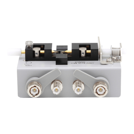
Overview Functions Functions Figure 1-2 16034H Parts Part Function Contact Pin Contract for DUT electrode LOW side Contact Pin connected to a instrument’s and HIGH side Contact Pin connected to a instrument’s H CUR, POT. Knob For lateral adjustment of HIGH side Contact Pin. - Page 8 Overview Functions...
-
Page 9: Operation
Operation 16034H Test Fixture Operation Manual Operation This chapter describes the proper methods for open and short correction and DUT measurement... -
Page 10: Performing Open And Shot Correction
DUT measurement. The following procedure shows correction and measurement by the 16034H. Take care to avoid rough handling and never allow any mechanical shock to the 16034H, especially against the contact pins from the sides or any to the parts mounted on top of the fixture. -
Page 11: Connecting The 16034H
16034H. Take care to avoid rough handling and never allow any mechanical shock to the 16034H, especially against the contact pins from the sides or any to the parts mounted on top of the fixture. 1. Set the cable length to 0m in the instrument. -
Page 12: Performing Short Correction
Operation Performing Short Correction Performing Short Correction The Short correction procedure is as follows 1. Push the HIGH side contact pin’s knob to the left to make firm contact with the LOW side contact pin (Figure 2-2). Tighten the contact pin locking screw to secure the HIGH side contact pin. -
Page 13: Performing Open Correction
Operation Performing Open Correction Performing Open Correction The open correction procedure is as follows 1. Push the HIGH side contact pin’s so that the distance between the HIGH and the LOW contact pins matches the DUT’s width (Figure 2-3). It is recommended that you place the DUT on the measuring stage and precisely position the HIGH side contact pin to actual DUT width. -
Page 14: Dut Measurement
Operation DUT Measurement DUT Measurement Before performing DUT measurement, open and short correction should be done as described in the previous sections. If measurement frequency is over 3 MHz, perform load correction before the DUT measurement described later onwards. 1. Adjust the HIGH side contact pin so that the DUT is positioned on the center of the measuring stage and secure the contact pin with the contact pin locking screw. - Page 15 Operation DUT Measurement Measurement values can vary depending on contact pressure when measuring ferrite inductors or multi-layer ceramic capacitors with high permittivity. When measuring this kind of device, removing the E-ring can weaken the spring pre-load. However, this technique may increase contact resistance and thus degrades the accuracy of D parameter measurements.
-
Page 16: Dut Measurement Over 3 Mhz
Operation DUT measurement over 3 MHz DUT measurement over 3 MHz Before performing DUT measurement over 3 MHz, performing load correction is recommended. The proportional error factor in the additional error caused by the fixture is in proportion to the frequency squared. Therefore, the error increases greatly as the frequency goes high. -
Page 17: Specifications And Supplemental Performance Characteristics
Specifications and Supplemental Performance Characteristics 16047A Test Fixture Operation and Service Manual Specifications and Supplemental Performance Characteristics This chapter provides specifications and supplemental performance characteristics of the 16034H test fixture. -
Page 18: Specifications
Specifications and Supplemental Performance Characteristics Specifications Specifications Applicable Instruments LCR meters and Impedance Analyzers with four-terminals Applicable DUT Type Chip components Applicable DUT dimensions Maximum Voltage ± 40 V peak max. (AC+DC) Operating temp. 0°C to +55°C Environment 15% to 95%RH (@ wet bulb temp. 40°C) humidity Non Operating temp. -
Page 19: Supplemental Performance Characteristics
Specifications and Supplemental Performance Characteristics Supplemental Performance Characteristics Supplemental Performance Characteristics This section provides useful data on the 16034H. These supplemental performance characteristics should not be considered specifications. Frequency Range With OPEN/SHORT correction 3MHz With OPEN/SHORT/LOAD correction 120MHz ... - Page 20 Specifications and Supplemental Performance Characteristics Supplemental Performance Characteristics where Dx is the measured value of D. It is necessary for Ze to be below 10 %. D is not expressed as a percentage but as an absolute value. Rs (ESR) Measurement Additional error Rse[%] of the Rs measurement is calculated by additional error Ze [%] of |Z| measurement as follows.
-
Page 21: Contact Pressure
Specifications and Supplemental Performance Characteristics Supplemental Performance Characteristics Contact Pressure The following data are supplemental performance characteristics for the spring that applies contact pressure. Spring constant ± 10 % 37 gf/mm Spring pre-load Approximately 400 g (without E-ring, approximately 20 g) - Page 22 Specifications and Supplemental Performance Characteristics Supplemental Performance Characteristics...
- Page 23 This information is subject to change without notice. © Keysight Technologies 1999-2019 Edition 6, January 2019 *16034-90012* 16034-90012 www.keysight.com...
Need help?
Do you have a question about the 16034H and is the answer not in the manual?
Questions and answers