Table of Contents
Advertisement
Advertisement
Table of Contents
Troubleshooting

Subscribe to Our Youtube Channel
Related Manuals for Keysight 3458A


Summary of Contents for Keysight 3458A
- Page 1 Keysight 3458A Multimeter Assembly-Level Repair Manual...
- Page 2 Conformity. understood and met. where in the EULA. Keysight shall be under no obligation to update, revise or otherwise modify the Software. With WARNING respect to any technical data as defined by FAR 2.101, pursuant to FAR...
-
Page 3: Keysight Technologies Warranty Statement
3 Keysight does not warrant that the operation of Keysight products will be interrupted or error free. If Keysight is unable, within a reasonable ntime, to repair or replace any product to a condition as warranted, customer will be entitled to a refund of the purchase price upon prompt return of the product. - Page 4 8 Keysight will be liable for damage to tangible property per incident up to the greater of $300,000 or the actual amount paid for the product that is the subject of the claim, and for damages for bodily injury or death, to the extent that all such damages are determined by a court of competent jurisdiction to have been directly caused by a defective Keysight product.
-
Page 5: U.s. Government Restricted Rights
1987)(or any equivalent agency regulation or contract clause), whichever is applicable. You have only those rights provided for such Software and Documentation by the applicable FAR or DFARS clause or the Keysight standard software agreement for the product involved. Keysight 3458A Assembly-Level Repair Manual... -
Page 6: Safety Symbols
Direct current (DC) Alternating current (AC) Caution, risk of danger (refer to this Caution, risk of electric shock manual for specific Warning or Caution information) Protective earth (ground) terminal Frame or chassis (ground) terminal Keysight 3458A Assembly-Level Repair Manual... -
Page 7: Safety Considerations
Failure to comply with these precautions or with specific warnings elsewhere in this manual violates safety standards for design, manufacture, and intended use of the instrument. Keysight Technologies assumes no liability for the customer’s failure to comply with these requirements. - Page 8 Return the product to Keysight for service and repair to ensure that safety features are maintained. – Measuring high voltages is al ways hazardous: ALL multimeter input terminals (both front and rear) must be considered hazardous whenever inputs greater than 42V (dc or peak) are connected to ANY input terminal.
-
Page 9: Waste Electrical And Electronic Equipment (Weee) Directive
To return this unwanted instrument, contact your nearest Keysight Service Center, or visit http://about.keysight.com/en/companyinfo/environment/takeback.shtml for more information. Sales and Technical Support To contact Keysight for sales and technical support, refer to the support links on the following Keysight websites: – www.keysight.com/find/3458A (product-specific information and support, software and documentation updates) –... - Page 10 THIS PAGE HAS BEEN INTENTIONALLY LEFT BLANK. Keysight 3458A Assembly-Level Repair Manual...
-
Page 11: Table Of Contents
..........39 Keysight 3458A Assembly-Level Repair Manual... - Page 12 AC converter assembly removal/installation procedures ..80 A/D converter assembly removal/installation procedures ..81 Inguard power supply assembly removal/installation procedures . 84 Keysight 3458A Assembly-Level Repair Manual...
- Page 13 ....134 Inguard power supplies troubleshooting ....135 Keysight 3458A Assembly-Level Repair Manual...
- Page 14 THIS PAGE HAS BEEN INTENTIONALLY LEFT BLANK. Keysight 3458A Assembly-Level Repair Manual...
- Page 15 .......100 Figure 3-22 Wire/Cable locations on front/rear terminals switch Keysight 3458A Assembly-Level Repair Manual...
- Page 16 ..... . . 133 Figure 4-3 Inguard power supply ......136 Keysight 3458A Assembly-Level Repair Manual...
- Page 17 ......112 Table 4-2 Self-test error messages and probable causes ..126 Keysight 3458A Assembly-Level Repair Manual...
- Page 18 THIS PAGE HAS BEEN INTENTIONALLY LEFT BLANK. Keysight 3458A Assembly-Level Repair Manual...
- Page 19 Keysight 3458A Multimeter Assembly-Level Repair Manual General Information Introduction Manual Description Instrument Description Safety Considerations Instrument Identification Tools and Equipment Required...
-
Page 20: General Information
The information in this manual is for the use of Service Trained Personnel WARNING only. To avoid electrical shock, do not perform any procedures in this manual or do any servicing to the 3458A, unless you are qualified to do so. Keysight 3458A Assembly-Level Repair Manual... -
Page 21: Manual Description
For more operating information, refer to the 3458A Multimeter User’s Guide. Chapter 3 - Disassembly/Assembly Procedures and Parts List Contains the disassembly/assembly procedures for the 3458A Printed Circuit Board Assemblies. The section also has a mechanical parts list. Chapter 4 - Assembly Level Troubleshooting Contains a block diagram theory of operation and assembly level troubleshooting information. -
Page 22: Instrument Description
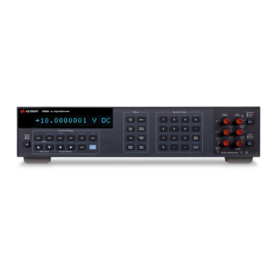
General Information Instrument Description The 3458A is a high precision digital multimeter that can measure AC and DC volts, AC and DC current, AC+DC volts, AC+DC current, resistance, period, and frequency. It can also perform complex math calculations. The multimeter has a maximum reading rate of 100,000 readings/sec. The maximum input voltage is 1000 V peak and the resolution is from 4 1/2 to 8 1/2 digits. -
Page 23: Safety Considerations
General Information Safety Considerations The 3458A is a safety class 1 instrument provided with a protective earth terminal. The instrument and manuals should be reviewed for safety markings and instructions before operation. Refer to the Safety Summary preceding this section for appropriate safety instructions and markings covering the instrument. -
Page 24: Instrument Identification
General Information Instrument Identification Keysight instruments are identified by a two part, ten-digit serial number. The serial number is located on the instrument's rear panel between the rear terminals and fan filter. The number is in the form 0000A00000. The first four digits, called the serial number prefix, is the same for all identical instruments. -
Page 25: Tools And Equipment Required
6 Large screwdriver (e.g., #2 Pozidriv; for Display Logic assembly only) Test equipment required You need the following to troubleshoot the 3458A. 1 4 1/2 digit digital multimeter that can measure +5 V, +18 V, and –18 V DC. 2 Computer with GPIB capability (for GPIB failures only). - Page 26 General Information THIS PAGE HAS BEEN INTENTIONALLY LEFT BLANK. Keysight 3458A Assembly-Level Repair Manual...
- Page 27 Keysight 3458A Multimeter Assembly-Level Repair Manual Operating Information Introduction Before Applying Power Applying Power Operating from the Front Panel Operating from Remote...
-
Page 28: Operating Information
Operating Information Introduction This section summarizes the 3458A operating information. The 3458A Multimeter User’s Guide has the complete operating information. Keysight 3458A Assembly-Level Repair Manual... -
Page 29: Before Applying Power
1.5A 250V NTD FE UL 2110-0043 220 VAC 198 VAC to 242 VAC 0.5A 250V TD FE UL 2110-0202 240 VAC 216 VAC to 250 VAC 0.5A 250V TD FE UL 2110-0202 Figure 2-1 AC line voltage switch positions Keysight 3458A Assembly-Level Repair Manual... -
Page 30: Figure 2-2 Power Cords
United States 1820-0698 240 V 10 A Power cords supplied by Keysight have polarities matched to the power input socket on the instrument. NOTE: Plugs are viewed from connector and shape of molded plug may vary within country. *CSA certification includes only these power cords. -
Page 31: Applying Power
EMASK 32767 Enable all error conditions END OFF Disable GPIB EOI function EXTOUT ICOMP, NEG Input complete EXTOUT signal, negative pulse FIXEDZ OFF Disable fixed input resistance FSOURCE ACV Frequency and period source is AC voltage Keysight 3458A Assembly-Level Repair Manual... -
Page 32: Table 2-5 Table
Level sync source event, auto synchronous AC voltage SWEEP lOOE-9,1024 Sample interval 100 nanoseconds, 1024 samples TARM AUTO Auto trigger arm event TBUFF OFF Disable external trigger buffering TIMER 1 1 second timer interval TRIG AUTO Auto trigger event Keysight 3458A Assembly-Level Repair Manual... -
Page 33: The Display
One or two real-time or post-process math operations enabled An error has been detected SHIFT The shift key has been pressed More information concerning the present configuration is available (use the MOREINFO right arrow key to view the information) Keysight 3458A Assembly-Level Repair Manual... - Page 34 If the ERR annunciator is illuminated at this point, an error was detected during NOTE or after the power-on self-test. You will learn how to determine the error later in this chapter in Reading the error register. Keysight 3458A Assembly-Level Repair Manual...
-
Page 35: Operating From The Front Panel
AC voltage, 2-wire resistance, AC+DC voltage, digitizing, and frequency or period measurements from a voltage input source. Refer to Chapter 3 for a CAUTlON concerning the multimeter's maximum input voltage and current. Keysight 3458A Assembly-Level Repair Manual... -
Page 36: Changing The Measurement Function
Standard 2-wire (plus guard) measurements Changing the measurement function The row of keys located directly under the display (FUNCTION keys) select the multimeter's standard measurement functions. Table 2-4 shows the FUNCTION keys and the measurement function selected by each. Keysight 3458A Assembly-Level Repair Manual... -
Page 37: Function Keys
AC+DC voltage measurements using the synchronous or random measurement methods. These functions can be selected from the front panel by accessing the appropriate command(s) using the alphabetic menu keys (these keys are discussed later in this section under Using the MENU keys). Keysight 3458A Assembly-Level Repair Manual... -
Page 38: Autorange And Manual Ranging
By repeatedly pressing the up arrow key, you can increment up to the highest range. When you reach the highest range, pressing the up arrow key no longer changes the range. To go to a lower range. Keysight 3458A Assembly-Level Repair Manual... -
Page 39: Self-Test
Always disconnect any input signals before you run self-test. If you leave an NOTE input signal connected to the multimeter, it cause a self-test failure. The self-test takes over 50 seconds. To run self-test. Press: Test If the self-test passed, the display shows: Keysight 3458A Assembly-Level Repair Manual... -
Page 40: Reading The Error Register
If the ERR annunciator is still illuminated, more errors have been recorded. Repeat the above key sequence until all errors have been read and the ERR annunciator is Keysight 3458A Assembly-Level Repair Manual... -
Page 41: Resetting The Multimeter
The multimeter begins the reset process with a display test which illuminates all display elements including the annunciators as shown in Figure 2-5. (By holding down the Reset key, the multimeter continuously performs its display test). Keysight 3458A Assembly-Level Repair Manual... -
Page 42: Using The Configuration Keys
The configuration keys (unshifted MENU keys) let you rapidly access the most frequently used multimeter features. Table 2-5 shows each key, the corresponding multimeter command, and the function of each. (These functions are discussed in detail in Chapter 3 Chapter Keysight 3458A Assembly-Level Repair Manual... -
Page 43: Configuration Key Functions
Operating Information Table 2-5 Configuration key functions We will use the Trig key to demonstrate how to use the configuration keys. Press: Trig The display shows: Keysight 3458A Assembly-Level Repair Manual... - Page 44 Press the up or down arrow key until the display shows: Press: Enter You have now changed the trigger event from auto (power-on state) to HOLD which causes the multimeter to stop taking readings. (Triggering is discussed in detail in Chapter Keysight 3458A Assembly-Level Repair Manual...
- Page 45 The multimeter again takes a single reading and then stops. Numeric parameters Some commands use numeric parameters. A numeric parameter is the actual value used by the multimeter. We will use the NPLC configuration key to demonstrate numeric parameters. Press: NPLC This display shows: Keysight 3458A Assembly-Level Repair Manual...
- Page 46 Many commands have more than one parameter. (Multiple parameters are separated by commas.) We will use the NRDGS command, which has two parameters, as an example of a command with multiple parameters. Press: N Rdge/ Trig The display shows: Keysight 3458A Assembly-Level Repair Manual...
-
Page 47: Using The Menu Keys
MENU keys labeled C, E, L, N, R, S, and T. Each of these letters corresponds to the area you will enter into the command menu. For example, to enter the menu with commands starting with T. Press: Recall State Keysight 3458A Assembly-Level Repair Manual... -
Page 48: Query Commands
(Use the right arrow key to view the entire response.) As another example, access the TEMP? command from the command menu and press Enter. This command returns the multimeter's internal temperature in degrees Centigrade. Keysight 3458A Assembly-Level Repair Manual... - Page 49 The QFORMAT command can be used to specify whether query responses will be NOTE numeric, alpha, or a combination of alpha and numeric. Refer to the QFORMAT command, in Chapter 6 of the 3458A User’s Guide, for more information. Keysight 3458A Assembly-Level Repair Manual...
-
Page 50: Display Control
(10). At this point, you can reenter the first parameter using the numeric keypad and the second parameter using the Menu Scroll keys. Press the Enter key to execute the edited command. Keysight 3458A Assembly-Level Repair Manual... - Page 51 For example, access and execute the SETACV RNDM command from the alphabetic command menu. Now press the front panel ACV key. Notice that the multimeter's MORE INFO annunciator is illuminated. This means there is more information available than is being displayed. Press: Keysight 3458A Assembly-Level Repair Manual...
-
Page 52: Digits Displayed
The NDlG command only masks digits from the display. It does not affect readings sent to reading memory or transferred over the GPIB bus. Also, you cannot view more digits than are being resolved by the multimeter. Keysight 3458A Assembly-Level Repair Manual... -
Page 53: Recall
By repeating the above keystrokes, you can recall previously executed commands. After recalling the desired command, you can modify it (see Display editing earlier in this section) and execute it by pressing Enter. Keysight 3458A Assembly-Level Repair Manual... -
Page 54: Operating From Remote
The displayed response is the device address. When sending a remote command, you append this address to the GPIB interface's select code (normally 7). For example, if the select code is 7 and the device address is 22, the combination is 722. Keysight 3458A Assembly-Level Repair Manual... -
Page 55: Changing The Gpib Address
When you send a query from remote, the multimeter does not display the response as it did when you executed the command from its front panel. Instead, the multimeter sends the response to its output buffer. The output buffer is a Keysight 3458A Assembly-Level Repair Manual... -
Page 56: The Local Key
Use the computer's input statement to get the response from the output buffer. For example, the following program reads the response (3458A) and prints it. 10 ENTER 722;A$ 20 PRINT A$ 30 END The same technique allows you to get readings from the multimeter. - Page 57 Keysight 3458A Multimeter Assembly-Level Repair Manual Disassembly/Assembly Procedures and Parts List Introduction Static Handling Clean Handling Printed Circuit Assembly Identification Covers Removal/Installation Procedures Assemblies Removal/Installation Procedures Replaceable Parts...
-
Page 58: Disassembly/Assembly Procedures And Parts List
Disassembly/Assembly Procedures and Parts List Introduction This section contains the 3458A Covers and Printed Circuit Assemblies Disassembly/Assembly procedures. Also included is the 3458A Parts Lists and listings of printed circuit board assemblies. Only personnel with knowledge of electronic circuitry and an awareness with... -
Page 59: Static Handling
— Only proper containers should be used for shipping, storing or transporting assemblies. This is required on any assembly shipped to Keysight Technologies for repair or replacement. -
Page 60: Clean Handling
Disassembly/Assembly Procedures and Parts List Clean Handling Due to the accuracy of the 3458A, use the following clean handling techniques when removing/installing printed circuit board assemblies. — Handle the assemblies only by their edges. — Be sure to place them on a clean workbench away from dirty or dusty conditions. -
Page 61: Printed Circuit Assembly Identification
This is done by using the board part number, followed by the engineering revision code (ERC) on the board. For example: 03458-66505-2825 would identify a particular printed circuit board in the 3458A. The board part number is 03458-66505 and the ERC is 2825. Board part number The Keysight Technologies part number of a printed circuit board is etched on the board. -
Page 62: Figure 3-1 Right Side Handle Removal/Installation
Disassembly/Assembly Procedures and Parts List NOTE The label numbers in Figure 3-1 Figure 3-6 show the order of cover removal. Use reverse order for installation. Figure 3-1 Right side handle removal/installation Keysight 3458A Assembly-Level Repair Manual... -
Page 63: Covers Removal/Installation Procedures
Disassembly/Assembly Procedures and Parts List Covers Removal/Installation Procedures The following procedures show how to remove the top/bottom covers and shields on the 3458A. Removal of the covers and shields are required to replace the printed circuit board assemblies. Tools required... -
Page 64: Figure 3-2 Remove/Install Left Side Handle
12 If you do not wish to remove the bottom cover, continue with step 14. 13 Turn the 3458A over so its top sits on your workbench. To remove the bottom cover, pull the cover toward the rear until it clears the front panel. Then slide it forward and away from the instrument. -
Page 65: Figure 3-3 Remove/Install Cover Ground Screws
Lift the shield off. 16 If you do not wish to remove the top shield, continue with step 19. Figure 3-3 Remove/Install cover ground screws Keysight 3458A Assembly-Level Repair Manual... -
Page 66: Figure 3-4 Remove/Install Rear Bezel
Disassembly/Assembly Procedures and Parts List Figure 3-4 Remove/Install rear bezel Keysight 3458A Assembly-Level Repair Manual... -
Page 67: Figure 3-5 Remove/Install Bottom Shield Screw
Pull the shield toward the rear of the instrument until the shield retainers line up with the slots in the shield. Lift the shield off. 19 Refer to the appropriate procedures in this section to remove the printed circuit board assembly. Keysight 3458A Assembly-Level Repair Manual... -
Page 68: Covers Installation Procedure
Disassembly/Assembly Procedures and Parts List Covers installation procedure Do the following: 1 Remove all connections to the 3458A. 2 If installing the top shield is not required, continue with step 6. 3 Refer to Figure 3-6. Turn the instrument over so its bottom sits on your workbench. -
Page 69: Figure 3-6 Remove/Install Top Shield Screw
Then push the cover toward the front of the instrument into the front panel bezel. 11 If installing the top cover is not required, continue with step 14. 12 Turn the 3458A over so the bottom sits on your workbench. Keysight 3458A Assembly-Level Repair Manual... - Page 70 19 Reinstall the right side handle strap. Use the #1 Pozidriv to reinstall side handle strap screws. 20 Your instrument is now ready for use. Keysight Technologies suggests that after you apply power that you perform an automatic calibration on the instrument.
-
Page 71: Assemblies Removal/Installation Procedures
Disassembly/Assembly Procedures and Parts List Assemblies Removal/Installation Procedures Table 3-1 lists all 3458A printed circuit board assemblies and assembly locations in the instrument. The assembly locations are also shown in installation procedure Figure 3-7 Figure 3-8. Table 3-1 3458A assemblies locations... -
Page 72: Dc Circuitry Assembly Removal/Installation Procedures
Disassembly/Assembly Procedures and Parts List DC circuitry assembly removal/installation procedures The following procedures show how to remove and install the DC Circuitry Printed Circuit Board Assembly. Figure 3-7 Assembly locations (top of instrument) Keysight 3458A Assembly-Level Repair Manual... -
Page 73: Figure 3-8 Assembly Locations (Bottom Of Instrument)
Disassembly/Assembly Procedures and Parts List Figure 3-8 Assembly locations (bottom of instrument) Refer to Figure 3-9 for the following procedures. Keysight 3458A Assembly-Level Repair Manual... - Page 74 Covers removal procedure in this section of the manual to remove the 3458A top cover and top shield. It is not necessary to remove the bottom cover and bottom shield. 2 Set the 3458A on your workbench with the top facing you.
- Page 75 Locate the blue wire connected to the power transformer. Plug the wire into the metal Inguard shield. b Locate the gray wire connected to the power transformer. Plug the wire into the metal inguard circuit ground. Keysight 3458A Assembly-Level Repair Manual...
-
Page 76: Figure 3-9 Dc Circuitry Assembly Removal/Installation
Disassembly/Assembly Procedures and Parts List Figure 3-9 DC circuitry assembly removal/installation Keysight 3458A Assembly-Level Repair Manual... -
Page 77: Dc Reference Assembly Removal/Installation Procedures
Covers removal procedure in this section of the manual to remove the 3458A top cover and top shield. It is not necessary to remove the bottom cover and bottom shield. 2 Set the 3458A on your workbench with the top facing you. - Page 78 3 Use the #TX10 Torx driver to install the two screws on the DC Reference assembly. 4 Use the Covers installation procedure in this section of the manual to install the 3458A top cover and top shield. Keysight 3458A Assembly-Level Repair Manual...
-
Page 79: Figure 3-10 Ac Converter Assembly Removal/Installation
Disassembly/Assembly Procedures and Parts List Figure 3-10 AC converter assembly removal/installation Keysight 3458A Assembly-Level Repair Manual... -
Page 80: Ac Converter Assembly Removal/Installation Procedures
Covers removal procedure in this section of the manual to remove the 3458A bottom cover and bottom shield. It is not necessary to remove the top cover and top shield. 2 Set the 3458A on your workbench with the bottom facing you. -
Page 81: A/D Converter Assembly Removal/Installation Procedures
Covers removal procedure in this section of the manual to remove the 3458A bottom cover and bottom shield. It is not necessary to remove the top cover and top shield. 2 Set the 3458A on your workbench with the bottom facing you. -
Page 82: Figure 3-11 A/D Converter And Inguard Logic Assembly
6 Use the #TX10 Torx driver to remove the three screws on the shield and the two screws on the A/D Converter and Inguard Logic assembly. Then remove the shield. 7 Unplug and remove the A/D Converter and Inguard Logic board from the inguard chassis. Keysight 3458A Assembly-Level Repair Manual... -
Page 83: Figure 3-12 Remove/Install Transformer Cable On Inguard Power Supply
5 Plug in both sets of the blue and gray fiber optic cables into the corresponding sockets on the A/D Converter and Inguard Logic assembly. 6 Use the Covers installation procedure in this section of the manual to install the 3458A bottom cover and bottom shield. Keysight 3458A Assembly-Level Repair Manual... -
Page 84: Inguard Power Supply Assembly Removal/Installation Procedures
Covers removal procedure in this section of the manual to remove the 3458A top/bottom covers and top/bottom shields. 2 Set the 3458A on your workbench with the top facing you. 3 Refer to Figure 3-12. Unplug the 5-wire cable from the Inguard Power Supply assembly. - Page 85 Then remove the board from the instrument. Installation procedure 1 Set the 3458A on your workbench with the bottom facing you. 2 Refer to Figure 3-13. Line up the Inguard Power Supply assembly with the slots in the chassis.
-
Page 86: Figure 3-14 Outguard Controller Assembly Removal
Disassembly/Assembly Procedures and Parts List Figure 3-14 Outguard controller assembly removal/installation 6 Set the 3458A on your workbench with the top facing you. 7 Refer to Figure 3-12. Locate the cable connected to the power transformer. Line up the cable plug with the socket on the Inguard Power Supply assembly. -
Page 87: Outguard Controller Assembly Removal/Installation Procedures
Covers removal procedure in this section of the manual to remove the 3458A top cover. It is not necessary to remove the bottom covers and the top/ bottom shields. 2 Set the 3458A on your workbench with the top facing you. -
Page 88: Outguard Power Supply Assembly Removal/Installation Procedures
Covers removal procedure in this section of the manual to remove the 3458A bottom cover. It is not necessary to remove the top cover and the top/ bottom shields. 2 Set the 3458A on your workbench with the top facing you. - Page 89 6 Locate the 8-pin cable that connects the Outguard Power Supply assembly to the power transformer. Unplug the cable from the power supply assembly. Move the cable so it lays on the outside of the outguard chassis. Keysight 3458A Assembly-Level Repair Manual...
-
Page 90: Figure 3-15 Outguard Power Supply Assembly Removal
Disassembly/Assembly Procedures and Parts List Figure 3-15 Outguard power supply assembly removal/installation Keysight 3458A Assembly-Level Repair Manual... - Page 91 “NEUTRAL” to the right terminal on the filter. These connections are also shown on a drawing on the Outguard Power Supply assembly. The drawing is located toward the rear of the board near ac line select switches. Keysight 3458A Assembly-Level Repair Manual...
-
Page 92: Figure 3-16 Guard And Power Pushrods, And Display Cable
Align the pushrod with the ac power switch shaft and push it onto the shaft. NOTE The label numbers in Figure 3-15 Figure 3-19 show the order of assembly removal. Use reverse order for installation. Figure 3-16 Guard and power pushrods, and display cable locations Keysight 3458A Assembly-Level Repair Manual... -
Page 93: Display Logic Assembly Removal/Installation Procedures
1 Use the Covers removal procedure in this section of the manual to remove the 3458A top/bottom covers and top/bottom shields. 2 Set the 3458A on your workbench with the bottom facing you. 3 Refer to Figure 3-16. Do the following: a Locate and pull the power switch pushrod off the power switch. -
Page 94: Figure 3-17 Top Trim And Front/Rear Pushrod Locations, And Unlock Panel
Then remove the pushrod by pulling it out of the front panel from the rear. 4 Set the 3458A on your workbench with the top facing you. Keysight 3458A Assembly-Level Repair Manual... -
Page 95: Figure 3-18 Remove Front Panel Assembly
Then remove the pushrod by pulling it out of the front panel from the rear. b With a small flat bladed screwdriver, pry the top trim loose and remove from the Front Panel assembly. 6 Set the 3458A on your workbench with the left side facing you. 7 Refer to Figure 3-18. - Page 96 15 Push the Display board toward the left (with input terminals at your right side) as far as it can go. Then pull its bottom up and lift it out from the Front Panel assembly. Keysight 3458A Assembly-Level Repair Manual...
-
Page 97: Figure 3-19 Remove/Install Screws On Front Terminals
Disassembly/Assembly Procedures and Parts List Figure 3-19 Remove/Install screws on front terminals Keysight 3458A Assembly-Level Repair Manual... -
Page 98: Figure 3-20 Remove/Install Display Screw
3-20. Use the #TX10 Torx driver to install the screw on the Display assembly. 4 Set the 3458A on your workbench with the right side facing you. 5 Carefully place the front terminals into the appropriate holes in the front panel. - Page 99 Then align the pushrod with the Front/Rear Terminals switch shaft and push it all the way onto the shaft. 14 Set the 3458A on your workbench with the bottom facing you. 15 Refer to Figure 3-16.
-
Page 100: Figure 3-21 Front/Rear Terminals Switch Assembly Removal
Disassembly/Assembly Procedures and Parts List Figure 3-21 Front/Rear terminals switch assembly removal/installation 16 Use the Covers installation procedure in this section of the manual to install the 3458A top/bottom covers and top/bottom shields. Keysight 3458A Assembly-Level Repair Manual... -
Page 101: Front/Rear Terminals Switch Removal/Installation Procedures
Covers removal procedure in this section of the manual to remove the 3458A top cover and top shield. It is not necessary to remove the bottom cover and bottom shield. 2 Set the 3458A on your workbench with the top facing you. - Page 102 Then align the pushrod with the Front/Rear Terminals switch shaft and push it all the way onto the shaft. 4 Use the Covers installation procedure in this section of the manual to install the 3458A top cover and top shield. Keysight 3458A Assembly-Level Repair Manual...
-
Page 103: Replaceable Parts
Disassembly/Assembly Procedures and Parts List Replaceable Parts Ordering information To order a part in the replaceable parts table, quote the Keysight part number, the check digit (abbreviated CD), and the quantity desired. Address the order to the nearest Keysight Technologies Sales Office. -
Page 104: Table
83486 Order by description 0.5 20MM-LG 03458-66504 PC assy-inguard power supply 28480 03458-66504 Screw-machine assembly M3 x 0515-0372 93907 Order by description 0.5 8MM-LG 03458-66505 PC assy-outguard controller 28480 03458-66505 PC assy-outguard controller 03458-66515 28480 03458-66515 (OPT 001) Keysight 3458A Assembly-Level Repair Manual... - Page 105 Screw-mach M4 x 0.7 0515-1404 93907 Order by description 55MM-LG PAN-HD 03458-60201 03458-60211 Assembly-front panel 28480 03458-40202 03458-40212 Panel (front) 28480 03458-69302 03458-49331 Window 28480 03458-81902 03458-81912 Keypad 28480 5041-8802 5041-9176 Trim (top front bezel) 28480 Keysight 3458A Assembly-Level Repair Manual...
- Page 106 Order by description .75-IN-LG Screw-machine assembly M3 x MP17 0515-0372 93907 Order by description 0.5 8MM-LG MP18 03458-00602 Shield-bottom 28480 03458-00602 Screw-mach M3.5 x 0.6 MP19 0515-1604 93907 Order by description 6MM-LG MP20 03458-04102 03458-04112 Cover-bottom 28480 Keysight 3458A Assembly-Level Repair Manual...
- Page 107 Fuseholder (current trmnl) 28480 03458-62101 03458-62111 Terminal block assy 28480 Terminal block assy insulator 03458-44105 03458-44115 28480 cover Battery-Li Coin Poly-carbon 1420-0523 fluoride 3V 0.5A-HR 30mm-DIA 28480 3.2mm-HT 5.5g XU132, 1420-0885 Battery Li-Ion 3V 120mAh 28480 XU133 Keysight 3458A Assembly-Level Repair Manual...
- Page 108 Disassembly/Assembly Procedures and Parts List THIS PAGE HAS BEEN INTENTIONALLY LEFT BLANK. Keysight 3458A Assembly-Level Repair Manual...
- Page 109 Keysight 3458A Multimeter Assembly-Level Repair Manual Assembly Level Troubleshooting Introduction Test Equipment Required 3458A Adjustments/Calibration Assemblies Removal/Installation Procedures 3458A Technical Description Assembly Level Troubleshooting Power Supplies Troubleshooting...
-
Page 110: Assembly Level Troubleshooting
Assembly Level Troubleshooting Introduction This section provides a technical description and assembly level troubleshooting procedures for the 3458A multimeter. Only personnel with knowledge of electronic circuitry and an awareness with WARNING the hazards involved should test and troubleshoot the instrument. -
Page 111: Test Equipment Required
1 A 4 1/2 digit digital multimeter that can measure +5 V, +18 V, and -18 V DC. This is only used to check and troubleshoot the power supplies. 2 A computer with GPIB capability to check the 3458A's GPIB operation. This is only required for an GPIB failure. -
Page 112: 3458A Adjustments/Calibration
Offset, DC Gain, etc.). It is also good practice to execute the “ACAL ALL” command after the covers have been removed and replaced on the instrument. Table 4-1 lists the 3458A assemblies and the required adjustments/calibration after assembly replacement. For information on how to adjust/calibrate the 3458A, refer to the 3458A Calibration Manual. -
Page 113: Assemblies Removal/Installation Procedures
Assembly Level Troubleshooting Assemblies Removal/Installation Procedures The procedures to replace the 3458A printed circuit board assemblies are found in Chapter 3 of this manual. Keysight 3458A Assembly-Level Repair Manual... -
Page 114: 3458A Technical Description
Assembly Level Troubleshooting 3458A Technical Description General description The 3458A is a very high precision digital multimeter that can measure AC or DC volts, AC or DC current, AC+DC volts, AC+DC current, resistance, period, and frequency. The 3458A can also perform complex math calculations. Its maximum reading rate is 100,000 readings/sec. - Page 115 Assembly Level Troubleshooting Figure 4-1 3458A simplified block diagram Keysight 3458A Assembly-Level Repair Manual...
-
Page 116: Outguard Section
RAM which were stored during instrument adjustment. GPIB circuitry The GPIB circuitry provides communication between the 3458A and other instruments and controllers connected to the GPIB. Instrument control commands are transferred to the main controller and measurement data is transferred from the main controller through the GPIB circuitry. -
Page 117: Inguard Section
AC circuitry (AC ranging, AC amplifier, and AC to DC converter). The AC and AC + DC volts to DC volts conversion method used is True RMS. This method is used since the converter must convert both DC and AC voltages. Keysight 3458A Assembly-Level Repair Manual... - Page 118 Track/hold requires a higher bandwidth than the DC circuitry provides. Current ranging The 3458A measures current by measuring the voltage across a shunt resistor. This voltage and the shunt resistor value are then used to calculate the current. The outguard circuitry calculates the correct current value.
- Page 119 The inguard controller controls the measurement process. It receives function and range data from the outguard and then sets the appropriate switches in the inguard. The inguard controller also controls the operation of the A/D converter. Keysight 3458A Assembly-Level Repair Manual...
-
Page 120: Assembly Level Troubleshooting
Assembly Level Troubleshooting 3458A failures To troubleshoot the 3458A, first determine what the failure is. Then use the information in the following paragraphs to determine the defective assembly. Failures can show up in a variety of ways. Some failures are obvious, like a completely inoperative instrument or a self-test failure. - Page 121 Chapter 3 of this manual to replace the Outguard Power Supply (A6) assembly. 3458A inoperative with unintelligible messages in display This normally indicates that the Display Logic is probably working but that the Outguard Logic may be inoperative. Do the following: 1 First check for a defective outguard power supply.
- Page 122 6 If after replacing the Outguard Power Supply (A6) assembly the test still fails, try replacing the (A5) Outguard Controller assembly. Go to the Assemblies Removal/Installation Procedures Chapter 3 of this manual to replace the assembly. Keysight 3458A Assembly-Level Repair Manual...
- Page 123 'SELF TEST FAILED' will also be displayed. Self-test error messages Any time the 3458A detects a self-test failure; a corresponding error message is stored into the auxiliary error registers. To determine what failed, this error message must be retrieved from the registers and displayed. To display the message, press the blue “SHIFT”...
- Page 124 Do this for all error messages recorded in the error registers. Refer to the Assemblies Removal/Installation Procedures Chapter 3 this manual to replace a defective assembly. Keysight 3458A Assembly-Level Repair Manual...
- Page 125 3458A Calibration Manual before troubleshooting performance test failures. If you are sure that the 3458A fails a performance test, determine what function is inaccurate and then replace the appropriate assembly. The following lists the functions and probable corresponding assemblies.
-
Page 126: Self-Test Error Messages And Probable Causes
A/D Converter and Inguard Salve Test: Isolator Date 03458-66503 Logic Slave Test: Intr Data AC Converter 03458-66502 Slave Test: DC Board DC Circuitry 03458-66501 Slave Test: AC Board AC Converter 03458-66502 Slave Test: Overload DC Circuitry 03458-66501 Keysight 3458A Assembly-Level Repair Manual... - Page 127 A/D Converter and Inguard Interpolator DAC Convergence 03458-66503 Logic A/D Converter and Inguard Reference Control Loop Failure 03458-66503 Logic Test Value Out of Range See text HPIB Outguard Controller 03458-66505 03458-66515 HPIB ASM Outguard Controller 03458-66505 Keysight 3458A Assembly-Level Repair Manual...
- Page 128 ROM 0 HIGH CHECKSUM Outguard Controller 03458-66505 03458-66515 ROM 1 HIGH CHECKSUM Outguard Controller 03458-66505 03458-66515 ROM 2 HIGH CHECKSUM Outguard Controller 03458-66505 03458-66515 NONVOLATILE RAM HIGH Outguard Controller 03458-66505 03458-66515 NONVOLATILE RAM LOW Outguard Controller 03458-66505 03458-66515 Keysight 3458A Assembly-Level Repair Manual...
- Page 129 This failure can be caused by a defective cable or an inoperative isolation logic circuitry. Note that the Ext Out function can be disabled by the “EXTOUT 0" command. Be sure the function is enabled before troubleshooting the failure. To enable the function, reset the instrument. Keysight 3458A Assembly-Level Repair Manual...
- Page 130 Press the “Trig” key on the MENU keyboard. “TRIG” should now be displayed with a flashing cursor next to it. b Press the “UP ARROW” key on the FUNCTION/RANGE keyboard three times. “TRIG EXT” should now be displayed. Keysight 3458A Assembly-Level Repair Manual...
- Page 131 Press the “Enter” key on the NUMERIC/USER keyboard. The instrument should now be in the external trigger mode. 4 While viewing the 3458A display, temporarily connect a cliplead between chassis ground and the Ext Trig connection on the Ext Out/Ext Trig connector (P301).
- Page 132 (for example. 24 hours to 2 years) corresponding to the test limits against which the instrument is tested. This failure may be because of the 3458A's long-term stability. A defective DC Reference (A9) assembly causes this failure. Go to the...
-
Page 133: Power Supplies Troubleshooting
Refer to Figure 4-2 to locate the 8-pin cable that connects the Outguard Power Supply (A6) assembly to the power transformer. Unplug the cable at the power supply assembly. Keysight 3458A Assembly-Level Repair Manual... -
Page 134: Outguard Power Supplies Troubleshooting
Unplug the cable at the power supply assembly. d Replace the ac power fuse with a new one. Apply AC power to the 3458A and turn it on. e If the fuse still blows, replace the power transformer. -
Page 135: Inguard Power Supplies Troubleshooting
7 If the power supply voltage that was low is now good, the DC Circuitry (A1) assembly is defective. Go to the Assemblies Removal/Installation Procedures Chapter 3 of this manual to replace the assembly. Keysight 3458A Assembly-Level Repair Manual... - Page 136 12 If the power supply voltage is still low, the Inguard Power Supply (A4) assembly is defective. Go to the Assemblies Removal/Installation Procedures Chapter 3 of this manual to replace the assembly. Keysight 3458A Assembly-Level Repair Manual...
- Page 137 This information is subject to change without notice. Always refer to the Keysight website for the latest revision. © Keysight Technologies 1988 - 2018 Edition 5, April 2018 Printed in Malaysia *03458-90011* 03458-90011 www.keysight.com...
Need help?
Do you have a question about the 3458A and is the answer not in the manual?
Questions and answers