Table of Contents
Advertisement
Siemens Energy & Automation, Inc
Large Drives A
https://www.robiconperfectharmony.com/
500 Hunt Valley Road, New Kensington, PA, USA, 15068
Phone:
724-339-9500
Fax:
724-339-9562
Web:
www.siemens.com
U
'
SER
S MANUAL
FOR
A
C
IR
OOLED
P
H
ERFECT
GENIII
/
E
A
S
DJUSTABLE
PEED
N
G
WITH
EXT
ENERATION
Manual Number: A1A19000405A
Version 1.3
June 2009
Customer Support Phone:
Customer Support Web:
Customer Support E-mail:
ARMONY
S
ERIES
AC M
D
OTOR
RIVES
C
ONTROL
.
1-800-333-7421 (24-hours)
www.siemens.com/automation/support-request
CustomerSupport@siemens.com
Advertisement
Table of Contents

Related Manuals for Siemens PERFECT HARMONY GENIII/E Series


Summary of Contents for Siemens PERFECT HARMONY GENIII/E Series
- Page 1 PEED OTOR RIVES WITH ENERATION ONTROL Manual Number: A1A19000405A Version 1.3 June 2009 Siemens Energy & Automation, Inc Large Drives A https://www.robiconperfectharmony.com/ 500 Hunt Valley Road, New Kensington, PA, USA, 15068 Phone: 724-339-9500 Customer Support Phone: 1-800-333-7421 (24-hours) Fax: 724-339-9562 Customer Support Web: www.siemens.com/automation/support-request...
- Page 2 For technical assistance and Field Service emergency support in the area nearest to you, please call the 1.800.333.7421 toll-free number. Version History Version 1.0 (original) August 2003 Version 1.1 October 2003 Version 1.2 (ECO - 79B92611) (ECR - 13140) September 2008 Version 1.3 (ECO - 79C18180) (ECR - 13710) June 2009 ©...
-
Page 3: Table Of Contents
Perfect Harmony GENIII/e User’s Manual Table of Contents Table of Contents Safety Precautions and Warnings...................iii About This Manual ......................v Separation of Manuals..................... v Reference Tools....................... v Conventions Used in this Manual ................vi Chapter 1: Introduction....................1-1 Introduction to the Perfect Harmony..............1-1 Clean Power Input..................1-1 High Power Factor and Nearly Perfect Sinusoidal Input Currents ....1-2 Nearly Perfect Sinusoidal Output Voltages ..........1-2... - Page 4 Perfect Harmony GENIII/e User’s Manual Table of Contents Table of Contents Arrow Keys ....................3-8 Diagnostic Indicators ..................3-12 The Display ....................3-13 Menu Descriptions .....................3-18 Motor Menu (1) Options ................3-22 Drive Menu (2) Options ................3-27 Stability Menu (3) Options................3-36 Auto Menu (4) Options ................3-42 Main Menu (5) Options................3-53 Log Control Menu (6) Options ..............3-56 Protect Menu (7) Options................3-58...
-
Page 5: Safety Precautions And Warnings
Perfect Harmony GENIII/e User’s Manual Safety Precautions and Warnings Safety Precautions and Warnings Perfect Harmony drives are designed with considerable thought to personal safety. However, as with any piece of high power equipment, there are numerous internal connections that present potentially lethal voltages. In addition, some internal components are thermally hot to the touch. - Page 6 • When returning components to Siemens LD A, always use static-safe packing. This limits any fur- ther component damage due to ESD. Additional safety precautions and warnings appear throughout this manual. These important messages should be followed to reduce the risk of personal injury or equipment damage.
-
Page 7: About This Manual
If you have any comments or suggestions to improve the organization or increase the usability of this manual, please complete the Readers’ Comments Form located at the end of this manual and return it to Siemens LD A Document Control. -
Page 8: Conventions Used In This Manual
About This Manual Perfect Harmony GENIII/e User’s Manual Conventions Used in this Manual The following conventions are used throughout this manual: • This manual is for use with the CE-marked Perfect Harmony product line. • The terms “Perfect Harmony,” “VFD,” “variable frequency drive,” and “drive” are used interchangeably throughout this manual. -
Page 9: Chapter 1: Introduction
1.1 Introduction to the Perfect Harmony The Perfect Harmony is a series of pulse-width modulated, variable frequency AC motor drives designed and manufactured by Siemens LD A. The Perfect Harmony drive system addresses the following power quality issues: • Providing clean power input •... -
Page 10: High Power Factor And Nearly Perfect Sinusoidal Input Currents
Introduction Perfect Harmony GENIII/e User’s Manual 1.1.2 High Power Factor and Nearly Perfect Sinusoidal Input Currents Power factor is a measure of the fraction of current that produces real power to the load. Typically, power factor is given as a percentage. A high power factor VFD (e.g., 95%) makes much better use of its input line current demand in producing real power to the motor than a VFD operating at a low power factor (e.g., 30%). - Page 11 Perfect Harmony GENIII/e User’s Manual Introduction The cabinet configurations of Perfect Harmony drives vary based on the horsepower of the drive, the number and type of cells, and other factors. However, cabinet configurations can generally be divided into two broad categories: •...
-
Page 12: Features Overview
Introduction Perfect Harmony GENIII/e User’s Manual 1.2 Features Overview Additional features of the Perfect Harmony drive include the following: • Redundant cooling blowers • High efficiency • Reliability • Modular construction • Surge arrestors • Fiber optic control circuitry • Soft start protection •... -
Page 13: Specifications
Perfect Harmony GENIII/e User’s Manual Introduction 1.3 Specifications Table 1-1 lists common electrical and mechanical specifications for all standard Perfect Harmony systems. Note that Perfect Harmony specifications may be changed without notice. Table 1-1: Common Specifications for Standard Perfect Harmony Systems Item Description GEN III: Up to 3,000 Hp at 6,300V... - Page 14 Introduction Perfect Harmony GENIII/e User’s Manual s s s s A1A19000405A: Version 1.3...
-
Page 15: Chapter 2: Hardware Components
Perfect Harmony GENIII/e User’s Manual Hardware Components CHAPTER Hardware Components 2.1 Hardware Configuration Figure 2-1 depicts a typical GEN III style line-up in which each VFD normally consists of a single cabinet with multiple sections. These sections, described below, are: •... - Page 16 Hardware Components Perfect Harmony GENIII/e User’s Manual Blowers Single Point Air Intakes Cooling for (Do Not Block) Small Units Transformer Section Customer Control Wiring And Control Power Section Control Section and Access to Cell Cabinet Split Cooling for Longer Lineup Transformer Section Control...
-
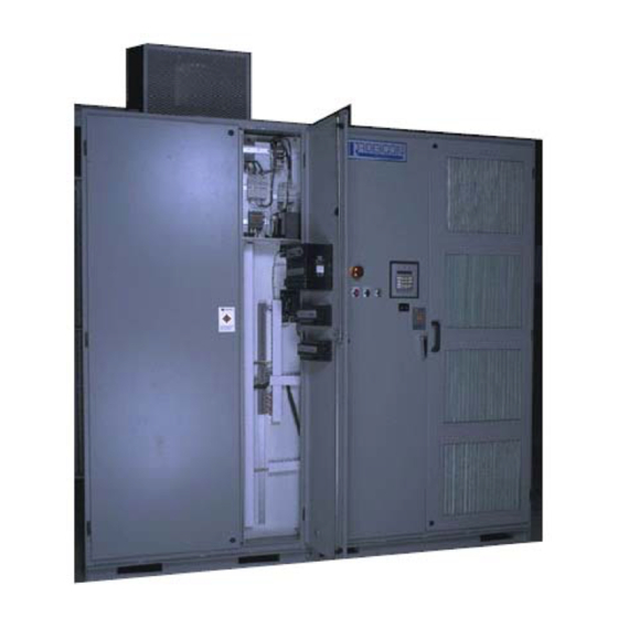
Page 17: Transformer Section
Perfect Harmony GENIII/e User’s Manual Hardware Components Figure 2-2: Typical GENIII/e style VFDs 2.1.1 Transformer Section The Transformer Section of the Perfect Harmony drive contains the input power transformer. Input power wires enter the drive through this section and output wires to the motor exit the drive through this section. The input and output power wiring can enter and exit the drive from either the top or bottom of this section. - Page 18 Hardware Components Perfect Harmony GENIII/e User’s Manual Blower Transformer Transformer Section Figure 2-3: Typical Power Input Cabinet (Front, Door Removed, and Side Views) s s s s A1A19000405A: Version 1.3...
- Page 19 Perfect Harmony GENIII/e User’s Manual Hardware Components Table 2-1: Field Connections and Major Components in the Transformer Section Item Description L1, L2, L3 Input power terminals T1, T2, T3 Output power terminals Multi-secondary, phase-shifting power transformer Control power transformer F24 - F35 Control fuses F21, F22 Blower fuses...
- Page 20 Hardware Components Perfect Harmony GENIII/e User’s Manual Figure 2-4: Field Connections and Major Components in the GEN III Transformer Section s s s s A1A19000405A: Version 1.3...
-
Page 21: Customer I/O Section
Perfect Harmony GENIII/e User’s Manual Hardware Components Figure 2-5: Field Connections and Major Components in the GENIII/e Transformer Section (left) and Cell Section (right) 2.1.2 Customer I/O Section The customer I/O section of the GEN III-style Perfect Harmony drive contains terminal blocks for customer control wiring connections, control power connections, and the blower control panel. -
Page 22: Cell And Control Sections (Geniii Cell Specifications)
Siemens’GEN III AC drive system is offered in 5 basic cell sizes (current ratings), grouped to provide output operating voltages of 3300 VAC (3 cells in series), 4160 VAC (4 cells in series), 4800 VAC (5 cells in series), and 6600 VAC (6 cells in series). - Page 23 Perfect Harmony GENIII/e User’s Manual Hardware Components Table 2-2: GENIII Cell Specification Details Output Cells in Drive Line-to-Line hp Range Available Cell Sizes Cells Per (Without Voltages(VAC) Phase Spares) 3,300 up to 1500 70A, 100A, 140A,200A, 260A 4,160 up to 2000 70A, 100A, 140A,200A, 260A 6,600 up to 3000...
- Page 24 Hardware Components Perfect Harmony GENIII/e User’s Manual Figure 2-8: Typical GENIII/e Cell Figure 2-9: Details of GENIII/e Terminals and Indicators s s s s 2-10 A1A19000405A: Version 1.3...
- Page 25 Perfect Harmony GENIII/e User’s Manual Hardware Components Blower Figure 2-10: Cell Section (Typical) of a GENIII style Perfect Harmony Drive A switch mode power supply located on the Cell Control/Gate Driver Board allows the control power to be derived from the individual 3-phase secondary connections of the transformer. The Control Section contains PC boards, which provide central control of the Perfect Harmony drive system.
- Page 26 Hardware Components Perfect Harmony GENIII/e User’s Manual Table 2-4: 3,300 VAC GENIII Cell Specifications: 9 Cells Total, 3 (630 VAC) Cells in Series Amps In Amps Out Losses Ventilation Length Weight Size 20,000 4,400 4,800 30,000 4,400 4,800 40,000 4,400 5,600 50,000 4,400...
- Page 27 Perfect Harmony GENIII/e User’s Manual Hardware Components Table 2-6: 6,600 VAC GENIII Cell Specifications: 18 Cells Total, 6 (630 VAC) Cells in Series Amps In Amps Out Losses Ventilation Length Weight Size 60,000 8,800 7,700 70,000 8,800 9,000 80,000 8,800 9,000 90,000 8,800...
- Page 28 Hardware Components Perfect Harmony GENIII/e User’s Manual Amps In Amps Out Losses Ventilation Length Weight Size 2500 190,000 15,000 12,000 375H 3000 228,000 15,000 13,400 500H 3500 266,000 15,000 14,900 660H 4000 304,000 15,000 16,400 660H Table 2-9: 4,160 VAC GENIII/e Cell Specifications: 12 Cells Total, 4 (690 VAC) Cells in Series Amps In Amps Out Losses...
- Page 29 Perfect Harmony GENIII/e User’s Manual Hardware Components Table 2-11: 6,600 VAC GENIII/e Cell Specifications: 18 Cells Total, 6 (690 VAC) Cells in Series Amps In Amps Out Losses Ventilation Length Weight Size 3500 266,000 28,000 21,900 315H 4000 304,000 28,000 23,800 315H 5000...
-
Page 30: Cell Bypass Option
Hardware Components Perfect Harmony GENIII/e User’s Manual 2.1.4 Cell Bypass Option As an option, each cell in the system can be equipped with a bypass contactor. This contactor will be automatically energized by the VFD master control if the associated cell malfunctions. Once the contactor is energized, the damaged cell is no longer electrically part of the system, which allows the VFD to resume operation. - Page 31 Perfect Harmony GENIII/e User’s Manual Hardware Components information and system program for the VFD, and therefore allows the Microprocessor Board to be replaced without the need to re-program the VFD. Note: If the Microprocessor Board is replaced, the Flash Disk should be moved to the new board. See Figure 2-13.
- Page 32 Hardware Components Perfect Harmony GENIII/e User’s Manual Modulator board Fiber Optic Cable Fiber Optic Interface boards To By-pass Board Communications board System Interface board Analog to Digital board Microprocessor board Power Supply connection Figure 2-12: Master Control System s s s s 2-18 A1A19000405A: Version 1.3...
- Page 33 Perfect Harmony GENIII/e User’s Manual Hardware Components Flash Disk Figure 2-13: Location of Flash Disk on Microprocessor Board s s s s A1A19000405A: Version 1.3 2-19...
- Page 34 Hardware Components Perfect Harmony GENIII/e User’s Manual Cell Special Transformer With 18 Isolated Cell Secondaries (9 for 3300 VAC) Keypad Cell Cell Cell Fiber RS485 Optic Interface Board Cell Input Power 3-phase AC Cell see Section 2.4.1 Microprocessor Cell Board Cell Cell ISA Bus...
-
Page 35: The Power Circuit
Perfect Harmony GENIII/e User’s Manual Hardware Components 2.4 The Power Circuit The basic power schematic for an 18 cell (4160 VAC) system is shown in Figure 2-14. Besides the direct operating information received from each cell by the Fiber Optic System, input voltage, output voltage, and current are also directly monitored. - Page 36 Hardware Components Perfect Harmony GENIII/e User’s Manual Input fuses for GENIII/e are not located in Cell Figure 2-15: Typical Power Cell Schematic ∇ ∇ ∇ s s s s 2-22 A1A19000405A: Version 1.3...
-
Page 37: Chapter 3: The Keypad And Display Interface
Perfect Harmony GENIII/e User’s Manual The Keypad and Display Interface CHAPTER The Keypad and Display Interface 3.1 Introduction The menu system is the software program that allows operators to navigate through hierarchical structures (menus), which contain related menu items. Menu items include parameters, pick lists, functions, and submenus (“nested” menus). -
Page 38: Fault Reset Key
The Keypad and Display Interface Perfect Harmony GENIII/e User’s Manual Figure 3-1: The Keypad and Display Interface of the Perfect Harmony Series Note: Parameter values are stored in a Flash Disk: a non-volatile memory area. When a parameter value is changed, the new value is saved internally. -
Page 39: Automatic Key
Perfect Harmony GENIII/e User’s Manual The Keypad and Display Interface • Acknowledge the alarm by pressing the [FAULT RESET] key on the keypad. Acknowledging an alarm will cause all alarms to be no longer displayed on the keypad display. However, if any alarm condition still exists, the Fault LED will flash red. -
Page 40: The 0-9 Key
The Keypad and Display Interface Perfect Harmony GENIII/e User’s Manual Figure 3-2: Comparison of the two Manual Control Modes 3.2.5 The 0-9 Key Numeric keys are centrally located on the keypad of the Perfect Harmony system. These 10 keys (labeled 0 through 9) provide the following functions: •... - Page 41 Perfect Harmony GENIII/e User’s Manual The Keypad and Display Interface Table 3-1: Hexadecimal Digit Assignments on the Perfect Harmony Keypad Key Combination HEX Value Decimal Equivalent Figure 3-3: Anatomy of a Numeric Keypad Key In addition to the speed menu feature, a second menu access feature is available for all remaining menus in the Perfect Harmony system.
- Page 42 The Keypad and Display Interface Perfect Harmony GENIII/e User’s Manual the [ENTER] key. If the number was a valid ID number, and the current security level permits access to that item, then the desired item will be displayed. Refer to Figure 3-4. Note: Any menu, parameter, or pick list can be accessed by ID.
-
Page 43: The Enter/Cancel Key
Perfect Harmony GENIII/e User’s Manual The Keypad and Display Interface 3.2.6 The Enter/Cancel Key The [ENTER] key is located below the up and down arrow keys on the right side of the keypad. This key is similar to the Return or Enter key on a standard PC keyboard. It is used to choose/accept a selection or confirm an operation. For example, after locating and displaying a parameter within the Perfect Harmony menu structure, the operator may use the [ENTER] key to edit the parameter’s value. -
Page 44: Arrow Keys
The Keypad and Display Interface Perfect Harmony GENIII/e User’s Manual 3.2.8 Arrow Keys There are four yellow arrow keys on the Perfect Harmony keypad. The up and down arrow keys ([ ] and [ ]) are located in the upper right corner of the keypad. The left and right arrow keys ([ ] and [ ]) are located on the lower row of the keypad. - Page 45 Perfect Harmony GENIII/e User’s Manual The Keypad and Display Interface Table 3-2: Summary of Common [SHIFT] Key Sequences Key Combination Description Speed menu to the Motor menu (from the default meter display) Enters hexadecimal “A” (from value edit and security prompts) Speed menu to the Drive menu (from the default meter display) Enters hexadecimal “B”...
- Page 46 The Keypad and Display Interface Perfect Harmony GENIII/e User’s Manual Key Combination Description Cancels/aborts the current action/keystroke or exits menu system Enters “numerical menu access mode”. The operator is then prompted to enter 1, 2, or 3 digit number for the associated menu Returns to the top of the current menu or submenu Restores the security level back to 0.
- Page 47 Perfect Harmony GENIII/e User’s Manual The Keypad and Display Interface Another feature of the arrow keys is that they can be used to edit the values of parameters. To edit a parameter value, the operator must first navigate through the menu structure (using the arrow keys) and locate the parameter to be changed.
-
Page 48: Diagnostic Indicators
The Keypad and Display Interface Perfect Harmony GENIII/e User’s Manual Table 3-3: Summary of Common Arrow Key Sequences Key Combination Description Used individually to navigate through the menu structure. Also used to change the active digit of parameter value (when in edit mode). -
Page 49: The Display
3.2.10 The Display After power up or reset, the Siemens identification and software version number is displayed for 2-3 seconds. Afterward, the meter display is shown on the LCD by default. The meter display is the starting point of the menuing system. - Page 50 The Keypad and Display Interface Perfect Harmony GENIII/e User’s Manual The following illustrations depict the 2-line, 24-character display in various modes of access as the operator attempts to locate and change the Ratio Control and Motor Frequency parameters. Figure 3-12 depicts the display immediately, following power up or system reset. Note that the first three variable displays (from the right) can be selected from a pick list using the Display Parameters (8000).
- Page 51 Perfect Harmony GENIII/e User’s Manual The Keypad and Display Interface Ratio control (2070) Figure 3-16: Status Display After [ ] Key Sequence Ratio control CANCEL ENTER ± 001 .0 (edit) Figure 3-17: Status Display After [ENTER] Key to Change a Parameter Ratio control *(edit) -03.0...
- Page 52 The Keypad and Display Interface Perfect Harmony GENIII/e User’s Manual Table 3-4: Summary of Operation Mode Displays: Line 1 of Mode Display Code Meaning Description Displayed after the [FAULT RESET] button is pressed. FRST Fault reset Note: This may not be visible because of the speed of response to a Fault Reset.
- Page 53 Perfect Harmony GENIII/e User’s Manual The Keypad and Display Interface Table 3-5: Summary of Operation Mode Displays: Line 2 of Mode Display Code Meaning Description NOMV No medium voltage No input line voltage detected. CR3 inhibit The CR3 or “Drive inhibit” input is asserted. Idle state The drive is ready to run but is in an idle state.
-
Page 54: Menu Descriptions
The Keypad and Display Interface Perfect Harmony GENIII/e User’s Manual 3.3 Menu Descriptions The following sections contain a condensed description of all parameter items available in the Perfect Harmony menu structure. Table 3-6 depicts main menus and submenus of the system. Each menu and submenu is associated with an ID shown in the ID column. - Page 55 Perfect Harmony GENIII/e User’s Manual The Keypad and Display Interface Table 3-6: Perfect Harmony Menu and Submenu Summary Menu Submenu Names Table Page Description Motor Parameter 1000 Table 3-7 3-23 Limits 1120 Table 3-8 3-24 Used to enter Motor Menu motor-specific data.
- Page 56 The Keypad and Display Interface Perfect Harmony GENIII/e User’s Manual Menu Submenu Names Table Page Description Speed Profile 4000 Table 3-32 3-44 Analog Inputs 4090 Table 3-33 3-45 Used to configure various speed setpoint, profile, and Analog Outputs 4660 Table 3-39 3-49 critical speed avoidance and...
- Page 57 Perfect Harmony GENIII/e User’s Manual The Keypad and Display Interface Menu Submenu Names Table Page Description Event Log 6180 Table 3-51 3-57 Used to configure and inspect the Logs Menu Alarm/Fault Log 6210 Table 3-52 3-57 event, alarm/fault, and historic logs of the VFD.
-
Page 58: Motor Menu (1) Options
The Keypad and Display Interface Perfect Harmony GENIII/e User’s Manual 3.3.1 Motor Menu (1) Options The Motor Menu (1) consists of the following menu options: • Motor Parameter Menu (1000) • Sync Motor Menu (1100) • Limit Protection Menu (1120) •... - Page 59 Perfect Harmony GENIII/e User’s Manual The Keypad and Display Interface Table 3-7: Motor Parameter Menu (1000) Parameter Units Default Description Enter the rated or base frequency of Motor frequency 1020 the motor from the nameplate. Enter the full load speed of the motor Full load speed 1030 1780...
- Page 60 The Keypad and Display Interface Perfect Harmony GENIII/e User’s Manual Table 3-8: Limits Menu (1120) Parameter Units Default Description Selects the type of motor thermal over- load protection from: Constant (fixed current-based): Use when only current limit based alarm is required.
- Page 61 Perfect Harmony GENIII/e User’s Manual The Keypad and Display Interface Parameter Units Default Description Enables or disables underload Underload enable 1180 Disable protection. Sets the current underload level based I underload 1182 10.0 90.0 on the rated motor current. Underload timeout 1186 10.0 0.01...
- Page 62 The Keypad and Display Interface Perfect Harmony GENIII/e User’s Manual Table 3-9: Speed Derate Curve Menu (1151) Parameter Units Default Description 0 Percent Break Sets the maximum motor load at 0% 1152 200.0 Point speed. 10 Percent Break Sets the maximum motor load at 10% 1153 31.6 200.0...
-
Page 63: Drive Menu (2) Options
Perfect Harmony GENIII/e User’s Manual The Keypad and Display Interface Table 3-11: Encoder Menu (1280) (Closed Loop Vector Control Only) Parameter Units Default Description Enter the number of pulses per revolu- Encoder 1 PPR 1290 10000 tion delivered by the encoder. Sets the gain of the filter for encoder Encoder filter gain feedback. - Page 64 The Keypad and Display Interface Perfect Harmony GENIII/e User’s Manual Parameter Units Default Description Control loop algorithm type selection. Volts per Hertz (V/Hz) for parallel motors. Open Loop Vector Control (OLVC) for single induction motors. Closed Loop Vector Control (CLVC) for single induction motors with Control loop type 2050...
- Page 65 Perfect Harmony GENIII/e User’s Manual The Keypad and Display Interface Table 3-13: Speed Setup Menu (2060) Parameter Units Default Description Used to adjust the scaling of the Ratio control 2070 100.0 -125.0 125.0 speed reference value. The forward max speed Speed fwd max limit 1 2080 100.0...
- Page 66 The Keypad and Display Interface Perfect Harmony GENIII/e User’s Manual Table 3-14: Speed Ramp Setup Menu (2260) Parameter Units Default Description Accel time 1 2270 3200.0 Acceleration time 1 in seconds. Decel time 1 2280 3200.0 Deceleration time 1 in seconds. Accel time 2 2290 3200.0...
- Page 67 Perfect Harmony GENIII/e User’s Manual The Keypad and Display Interface RPM = 120 x Freq/# of Poles Freq = RPM x (# of Poles)/120 Skip Freq 3 Skip Band 3 Skip Freq 2 Skip Band 2 Skip Freq 1 Skip Band 1 Controller Output (% Demand)
- Page 68 The Keypad and Display Interface Perfect Harmony GENIII/e User’s Manual Table 3-16: Spinning Load Menu (2420) Parameter Units Default Description Enable/Disable Spinning Load and set the direction of frequency scans: • • Forward • Reverse Spinning load • Both mode 2430 Enable Spinning Load if the drive is See Note below...
- Page 69 Perfect Harmony GENIII/e User’s Manual The Keypad and Display Interface Table 3-18: Cell Menu (2520) Parameter Units Default Description Installed cells/phase 2530 Installed cells per phase in the drive. Min cells/phase count 2540 Minimum cells per phase count. (n/3) Sets the value of the cell rated voltage: Cell voltage 2550...
- Page 70 The Keypad and Display Interface Perfect Harmony GENIII/e User’s Manual Parameter Units Default Description Displays bypass status: Same format as for cell status. Display Bypass Status 2620 Function A = available, B = active, U = unavailable. Allows bypassed cells to be reset when the drive is in an idle state.
- Page 71 Perfect Harmony GENIII/e User’s Manual The Keypad and Display Interface Table 3-19: Sync Transfer Menu (2700) Parameter Units Default Description Integral gain of the phase loop used dur- Phase I gain 2710 15.0 ing Up transfer. Proportional gain of the phase loop used Phase P gain 2720 12.0...
-
Page 72: Stability Menu (3) Options
The Keypad and Display Interface Perfect Harmony GENIII/e User’s Manual Table 3-21: Output Connection Menu (2900) Parameter Units Default Description Secondary side turns (assuming primary Filter CT 2910 turns = 5) of the CTs used to measure Secondary Turns filter capacitor currents. Sets the output filter inductor (impedance) value as a ratio of the base Filter Inductance... - Page 73 Perfect Harmony GENIII/e User’s Manual The Keypad and Display Interface Table 3-22: Stability Menu (3) (Parameters) Parameter Units Default Description Input Contains all of the submenus related to Processing 3000 Submenu drive line side processing. Menu See Table 3-23. Output Contains all of the submenus related to Processing 3050...
- Page 74 The Keypad and Display Interface Perfect Harmony GENIII/e User’s Manual Table 3-24: Output Processing Menu (3050) Parameter Units Default Description Menu contains parameters that effect Low freq comp 3060 Submenu motor flux calculation. See Table 3-25. This menu contains the flux control Flux control 3100 Submenu...
- Page 75 Perfect Harmony GENIII/e User’s Manual The Keypad and Display Interface Table 3-25: Low Frequency Compensation Menu (3060) Parameter Units Default Description Low Freq Wo 3070 12.6 100.0 Pole of hardware RC integrator. Low Frequency compensation gain for Low freq com gain 3080 scaling estimated flux.
- Page 76 The Keypad and Display Interface Perfect Harmony GENIII/e User’s Manual Table 3-27: Speed Loop Menu (3200) Parameter Units Default Description Speed PI regulator proportional gain Speed reg prop gain 3210 0.02 term. Automatically calculated after Auto-Tuning stage 2. Speed PI regulator integral gain Speed reg integral 3220 0.046...
- Page 77 Perfect Harmony GENIII/e User’s Manual The Keypad and Display Interface Table 3-29: Stator Resistance Estimator Menu (3300) Parameter Units Default Description This parameter enables or disables the stator resistance estimator Stator resistance est 3310 function. • • Stator resistance estimator filter Stator resis filter gain 3320 gain.
-
Page 78: Auto Menu (4) Options
The Keypad and Display Interface Perfect Harmony GENIII/e User’s Manual Table 3-31: Control Loop Test Menu (3460) Parameter Units Default Description This pick list selects the type of loop test desired (speed or torque). Test type 3470 Speed • Speed •... - Page 79 Perfect Harmony GENIII/e User’s Manual The Keypad and Display Interface Table 3-32: Speed Profile Menu (4000) Parameter Units Default Description Sets the % of speed cmd at which the Entry point 4010 200.0 drive begins following the speed cmd. Sets the % of speed cmd at which the Exit point 4020 150.0...
- Page 80 The Keypad and Display Interface Perfect Harmony GENIII/e User’s Manual Table 3-33: Analog Input Menu (4090) Parameter Type Description Analog input #1 4100 Submenu Menu for Analog input #1. See Table 3-34. Analog input #2 4170 Submenu Menu for Analog input #2. See Table 3-35. Auxiliary input #1 4500 Submenu...
- Page 81 Perfect Harmony GENIII/e User’s Manual The Keypad and Display Interface Table 3-34: Analog Input #1 Menu (4100) Parameter Units Default Description This parameter sets the input source for analog input #1 Source 4105 • • Ext 1-24 This parameter sets the operational mode for analog input 1.
- Page 82 The Keypad and Display Interface Perfect Harmony GENIII/e User’s Manual Parameter Units Default Description Select loss of signal action. • Preset Loss of signal action 4220 Preset • Maintain • Stop Loss of signal set- 4230 20.0 200.0 Loss of signal preset speed. point Table 3-36: Analog Input #3 Menu (4232) Parameter...
- Page 83 Perfect Harmony GENIII/e User’s Manual The Keypad and Display Interface Table 3-37: Auxiliary Input #1 Menu (4500) Parameter Units Default Description Auxiliary input source Source 4510 • • Ext 1-3 This parameter sets the operational mode for auxiliary input 1. Type 4520 4 –...
- Page 84 The Keypad and Display Interface Perfect Harmony GENIII/e User’s Manual Table 3-38: Auxiliary Input #2 Menu (4580) Parameter Units Default Description Auxiliary input source Source 4590 • • Ext 1-3 4 – 20mA This parameter sets the operational Type 4600 mode for analog input 1.
- Page 85 Perfect Harmony GENIII/e User’s Manual The Keypad and Display Interface Table 3-40: Pick list for Analog Variable parameters (all units are %) Motor Voltage Total Current Average Power Analog Input #1 Motor Speed Speed Demand Speed Reference Analog Input #2 Raw Flux Demand Flux Reference Current (RMS)
- Page 86 The Keypad and Display Interface Perfect Harmony GENIII/e User’s Manual Parameter Units Default Description Programmable speed setpoint that can be selected through an Speed setpoint 7 4310 -18000 18000 external contact and the system program. Programmable speed setpoint that can be selected through an Speed setpoint 8 4320 -18000...
- Page 87 Perfect Harmony GENIII/e User’s Manual The Keypad and Display Interface Table 3-42: Incremental Speed Setup Menu (4970) Parameter Units Default Description When selected through the SOP it will Speed increment 1 4971 200.0 increase the speed demand by the program amount. When selected through the SOP, it will Speed decrement 1 4972...
- Page 88 The Keypad and Display Interface Perfect Harmony GENIII/e User’s Manual Table 3-44: Comparator Setup Menu (4800) Submenu Description Submenus that contain 32 sets of comparators for custom use in the system program. Each comparator set (Compare 1 through Compare 32) consists of three parameters that are located in the comparator setup menus.
-
Page 89: Main Menu (5) Options
Perfect Harmony GENIII/e User’s Manual The Keypad and Display Interface Analog Input 11 Analog Input 23 Analog Input 12 Analog Input 24 3.3.5 Main Menu (5) Options The Main Menu (5) consists of the following menu options: • Motor Menu (1) •... - Page 90 The Keypad and Display Interface Perfect Harmony GENIII/e User’s Manual Table 3-47: Main Menu (5) Options Parameter (ID) Type Description Motor Menu Submenu Provides access to the Motor Menu. See Table 3-7. Drive Menu Submenu Provides access to the Drive Menu. See Table 3-12. Stability Menu Submenu Provides access to the Stability Menu.
- Page 91 Perfect Harmony GENIII/e User’s Manual The Keypad and Display Interface Table 3-48: Security Edit Functions Menu (5000) Parameter Type Description This function is used to change a menu item’s security level. When active, an “x” will appear as the first character on the second line of Change the display.
-
Page 92: Log Control Menu (6) Options
Proprietary Factory Use Only Note that menu options above security level 5 are more technical in nature and are typically used by Siemens personnel during commissioning or servicing. The Security Edit Menu (5000) can be accessed to change the factory default security settings. When the Perfect Harmony is configured for security level 7 access, the Security Edit Menu (5000) is visible from the Main Menu (5). - Page 93 Perfect Harmony GENIII/e User’s Manual The Keypad and Display Interface Table 3-53: Historic Log Menu (6250) The event log is stored in non-volatile battery backed up RAM. Seventy-eight “snapshots” are recorded at the slow cycle update rate, 58 before a fault occurs and 20 after. If the “Store in event log” is “On”, several historical logs can be stored.
-
Page 94: Protect Menu (7) Options
The Keypad and Display Interface Perfect Harmony GENIII/e User’s Manual Table 3-54: Pick List Variables for Historic Log (all units are %) Abbreviation Description Mtr Spd Motor speed Spd Ref Speed reference Spd Dmd Raw Speed Demand Trq I Cmd Torque Current Command Trq I Fdbk Torque Current Feedback... - Page 95 Perfect Harmony GENIII/e User’s Manual The Keypad and Display Interface Table 3-55: Drive Protect Menu (7) Parameters Parameter Units Default Description Input protection parameters. See Input Protection 7000 Submenu Table 3-56. Drive instantaneous overcurrent Drive IOC Setpoint 7110 150.0 50.0 200.0 setpoint (as a percentage of drive output rating).
- Page 96 The Keypad and Display Interface Perfect Harmony GENIII/e User’s Manual Table 3-56: Input Protect Menu (7000) Parameter Units Default Description Single phasing protection Single phasing 7010 Submenu parameters. See Table 3-57. Under voltage PI regulator Undervoltage prop gain 7060 10.0 proportional gain term.
-
Page 97: Meter Menu (8) Options
Perfect Harmony GENIII/e User’s Manual The Keypad and Display Interface Table 3-57: Single Phasing Menu (7010) Parameter Units Default Description Single phase detector PI regulator SPD prop gain 7020 10.0 proportional gain term. Single phase detector PI regulator integral SPD integral gain 7030 0.001 gain term. - Page 98 The Keypad and Display Interface Perfect Harmony GENIII/e User’s Manual Table 3-59: Display Parameters Menu (8000) Parameter Default Description Select variable 1 to be displayed on the LCD Status variable 1 8001 DEMD display. Pick List – See Table 3-60. Select variable 2 to be displayed on the LCD Status variable 2 8002...
- Page 99 Perfect Harmony GENIII/e User’s Manual The Keypad and Display Interface Table 3-60: Pick List Variables for the Front Display Abbreviation Description & Units Abbreviation Description & Units IMRF Magnetizing current ref (A) VAIN Phase A input voltage (V) ITRF Torque current ref (A) VBIN Phase B input voltage (V) FLDS...
- Page 100 The Keypad and Display Interface Perfect Harmony GENIII/e User’s Manual Abbreviation Description & Units Abbreviation Description & Units IAIN Phase A input current (A) SMFC Synch Motor Field Current (A) Phase B input current (A) %ESP Encoder Speed (%) ICIN Phase C input current (A) ERPM Encoder Speed (RPM)
-
Page 101: Communications Menu (9) Options
Perfect Harmony GENIII/e User’s Manual The Keypad and Display Interface Table 3-62: Input Harmonics Menu (8140) Parameter Units Default Description Selection for Harmonic Analysis • • Selection for HA 8150 • • • • Harmonics order 8160 30.0 Harmonic Order Harmonics integral 8170 0.001... - Page 102 The Keypad and Display Interface Perfect Harmony GENIII/e User’s Manual Table 3-63: Communications Menu (9) Parameters Parameter Units Default Description This menu contains all serial port Serial port setup 9010 Submenu setup parameters. See Table 3-64. Network Control 9943 Submenu Network 1 Configure 9900 Submenu...
- Page 103 Perfect Harmony GENIII/e User’s Manual The Keypad and Display Interface Table 3-64: Serial Port Setup Menu (9010) Parameter Units Default Description Designates the usage of the on board serial port. Serial port use 9020 Local • Local • Tool Designates the type of flow control used by the Xon/ serial port.
- Page 104 The Keypad and Display Interface Perfect Harmony GENIII/e User’s Manual Table 3-65: Serial Functions Menu (9110) Parameter Units Default Description Used to transfer the system program System program download 9120 Function to a remote system. Used to transfer the system program System program upload 9130 Function...
-
Page 105: Menu Setup For Multiple Configuration Files (Slaves)
Perfect Harmony GENIII/e User’s Manual The Keypad and Display Interface Table 3-66: TCP/IP Setup Menu (9300) Parameter Units Default Description Used to enter the system IP address 9310 172.16.106.16 0.0.0.0 255.255.255.255 IP address in dotted decimal. Used to enter the system Subnet mask 9320 255.255.0.0... - Page 106 The Keypad and Display Interface Perfect Harmony GENIII/e User’s Manual This function allows you to map the name of the flag in the SOP file, SOPConfigFileX_O, SOPConfigFileX_O where X = 1 to 8, to a name of a slave configuration file. Then, when the SOP program is (X = 1 to 8) running and this flag is set to ‘true’, the configuration file will be switched into memory.
- Page 107 Perfect Harmony GENIII/e User’s Manual The Keypad and Display Interface Table 3-67: Slave Parameter Parameter Units Default Description Enable multiple config file Multiple config files 9185 operation. Show active config file 9195 Display current active config file. Set the displayed file to be the Set active config file 9196 Defaults.sfg...
- Page 108 The Keypad and Display Interface Perfect Harmony GENIII/e User’s Manual Table 3-68: Parameter Menu - Slave Parameter Parameter Motor Menu Motor kW rating 1010 50 Percent Break Point 1156 Motor frequency 1020 100 Percent Break Point 1157 Full load speed 1030 Maximum Load Inertia 1159...
- Page 109 Perfect Harmony GENIII/e User’s Manual The Keypad and Display Interface Parameter Parameter Speed fwd max limit 1 2080 Skip bandwidth 2 2390 Speed fwd min limit 1 2090 Skip bandwidth 3 2400 Speed fwd max limit 2 2100 Freq avoid accel time 2410 Speed fwd min limit 2 2110...
- Page 110 The Keypad and Display Interface Perfect Harmony GENIII/e User’s Manual Parameter Parameter Flux reg prop gain 3110 Integ gain during brake 3290 Flux reg integral gain 3120 Enable braking 3360 Flux Filter Time Const 3130 Pulsation frequency 3370 Flux demand 3150 Brake power loss 3390...
- Page 111 Perfect Harmony GENIII/e User’s Manual The Keypad and Display Interface Parameter Parameter Historic log variable 1 6260 Historic log variable 5 6300 Historic log variable 2 6270 Historic log variable 6 6310 Historic log variable 3 6280 Historic log variable 7 6320 Historic log variable 4 6290...
- Page 112 The Keypad and Display Interface Perfect Harmony GENIII/e User’s Manual s s s s 3-76 A1A19000405A: Version 1.3...
-
Page 113: Appendix A: Glossary Of Terms
Perfect Harmony GENIII/e User’s Manual Glossary of Terms APPENDIX Glossary of Terms This appendix contains definitions of terms and abbreviations used throughout the Perfect Harmony series manuals. AND - AND is a logical Boolean function whose output is true if all of the inputs are true in SOP notation, AND is represented as “∗”... - Page 114 Glossary of Terms Perfect Harmony GENIII/e User’s Manual Debug Tool - see ToolSuite definition. DC link - The DC link is a large capacitor bank between the converter and inverter section of the drive. The DC link, along with the converter, establishes the voltage source for the inverter. De Morgan’s Theorem - The duality principal of Boolean algebra used to convert system logic equations into sum- of-products notation.
- Page 115 Perfect Harmony GENIII/e User’s Manual Glossary of Terms numbers in powers of 10, the base 16 number system uses the numerals 0, 1, 2, 3, 4, 5, 6, 7, 8, 9, A, B, C, D, E, and F to make numbers in powers of 16. Historic log - The historic log is a troubleshooting/diagnostic tool of the Perfect Harmony NXG control.
- Page 116 Glossary of Terms Perfect Harmony GENIII/e User’s Manual Manual mode - Manual mode is a control scheme of the Perfect Harmony in which the desired velocity of the drive is set manually by the operator. In local manual mode, the desired velocity is set using the up and down arrow keys on the front keypad of the drive.
- Page 117 (2) SOP, when used as a filename extension, refers to System Operating Program. SOP Utilities - The program within the Siemens LD A ToolSuite used for converting between text and machine loadable code. It can also be used for uploading and downloading files over the RS232 connection.
- Page 118 Glossary of Terms Perfect Harmony GENIII/e User’s Manual ToolSuite - Is the suite of programs developed by Siemens that allows easier access to the NXG drive for programming and monitoring. It is comprised of the following components: • ToolSuite Launcher - also referred to as ToolSuite; used for coordinating other tools.
-
Page 119: Appendix B: Commonly Used Abbreviations
Perfect Harmony GENIII/e User’s Manual Commonly Used Abbreviations APPENDIX Commonly Used Abbreviations This appendix contains a list of symbols and abbreviations commonly used throughout the Perfect Harmony series of manuals. s s s s A1A19000405A: Version 1.3... - Page 120 Commonly Used Abbreviations Perfect Harmony GENIII/e User’s Manual Table B-1: Commonly Used Abbreviations Abbreviation Meaning • Boolean AND function Addition or Boolean OR ≥ greater than or equal to ≤ less than or equal to ° degrees “ inches Σ Summation τ...
- Page 121 Perfect Harmony GENIII/e User’s Manual Commonly Used Abbreviations Abbreviation Meaning Digital-to-analog (converter) Decibel Direct Current Digital Control Rack Distributed Control System decel Deceleration deg, ° Degrees DHMS Down hole monitoring system Division Demand Error Electrically Commutated Extra Low Voltage Electromagnetic Compatibility Electromotive Force Electromagnetic Interference Encoder Power Supply...
- Page 122 Commonly Used Abbreviations Perfect Harmony GENIII/e User’s Manual Abbreviation Meaning Hertz Integral (PID) Identification International Electrotechnical Commission IEEE Institute of Electrical and Electronic Engineers IGBT Insulated Gate Bipolar Transistor Input in, “ Inches Inhibit Input(s)/Output(s) I/O Breakout Board Instantaneous Overcurrent Input Protection 1,000 (e.g., Kohm) KiloHertz...
- Page 123 Perfect Harmony GENIII/e User’s Manual Commonly Used Abbreviations Abbreviation Meaning Normally Closed NEMA National Electrical Manufacturer’s Association Non-Maskable Interrupt Normally Open NVRAM Non-Volatile Random Access Memory Next Generation Control NXG II Next Generation Control II oamp Output Current OLVC Open Loop Vector Control Overmodulation Out of Saturation (IGBT) overld...
- Page 124 Commonly Used Abbreviations Perfect Harmony GENIII/e User’s Manual Abbreviation Meaning Revolutions Per Minute Resistance Temperature Detector Remote Terminal Unit Receive (RS232 Communications) Second(s) Signal Conditioning Board Silicon Controlled Rectifier Second(s) Serial Synchronous Motor Control Sum of Products; System Operating Program Speed stab Stability...
- Page 125 Perfect Harmony GENIII/e User’s Manual Commonly Used Abbreviations ∇ ∇ ∇ s s s s A1A19000405A: Version 1.3...
- Page 126 Commonly Used Abbreviations Perfect Harmony GENIII/e User’s Manual s s s s A1A19000405A: Version 1.3...
- Page 127 Perfect Harmony GENIII/e User’s Manual Index Index Numerics cell control system 2-16 cell control/gate driver board 2-11 2-16 12-pulse wave form 1-1 cell malfunctions 2-16 3-phase secondary connections 2-11 Cell Menu (2520) 3-27 50 Hz 2-11 cells 6-pulse wave form 1-1 damage due to overheating iv cells control 2-11 cells control boards 2-9...
- Page 128 Index Perfect Harmony GENIII/e User’s Manual Control Loop Test Menu (3460) 3-19 3-36 3-42 Encoder Menu (1280) 3-19 3-27 control power iv 2-11 2-16 Enter Fixed Value 3-52 warning on disconnecting iv Enter Security Code Function 3-54 control power connections 2-7 enter security level 3-55 Control power disconnect switch 2-5 event log 3-21...
- Page 129 Perfect Harmony GENIII/e User’s Manual Index Manuals v master cell current 2-15 I/O section 2-7 master control 2-9 IEEE 519-1992 requirements 1-1 master control components 2-8 induction motors 1-2 master control system 2-11 Inhibit 3-55 master control system module 2-16 input 2-3 medium voltage input control power cable access 2-2...
- Page 130 Index Perfect Harmony GENIII/e User’s Manual preventing changes to 3-56 security features 3-20 prohibiting changes to 3-55 security level parameters storage in system module 2-16 changing 3-55 PCplus 3-68 security levels 3-56 PED A-4 setting 3-56 Perfect Harmony Features 1-3 Select Language Function 3-54 phase shifting transformer 2-11 separation points 2-2...
- Page 131 Perfect Harmony GENIII/e User’s Manual Index terminal strip for metering 2-5 thermally hot components iii torque and velocity loop gains 3-19 torque pulsations (VFD-induced) 1-2 total harmonic distortion of the source current 1-1 Transformer 2-1 transformer 2-5 2-15 transformer cabinet 2-1 transmit data 3-68 transporting precautions iv troubleshooting iii...
- Page 132 Index Perfect Harmony GENIII/e User’s Manual A1A19000405A: Version 1.3...
-
Page 133: Notes
Perfect Harmony GENIII/e User’s Manual NOTES NOTES s s s s A1A19000405A: Version 1.3... - Page 134 NOTES Perfect Harmony GENIII/e User’s Manual s s s s A1A19000405A: Version 1.3...
- Page 135 Perfect Harmony GENIII/e User’s Manual NOTES s s s s A1A19000405A: Version 1.3...
- Page 136 NOTES Perfect Harmony GENIII/e User’s Manual ∇ ∇ ∇ s s s s A1A19000405A: Version 1.3...
-
Page 137: Reader Comments Form
After completing this form, please remove this page from the manual (or photocopy it) and either mail, E-mail or fax it back to the Documentation Department at Siemens LD A. These are mechanisms through which you can positively effect the documentation that you receive from Siemens. Thank you for your feedback. - Page 138 Perfect Harmony GENIII/e User’s Manual Additional Comments Thank you for your comments. Please mail, fax or e-mail your comments to: Attention: Documentation Control Siemens LD A 500 Hunt Valley Road New Kensington, PA 15068 Phone: (724) 339-9500 Fax: (724) 339-9562 E-mail: DocumentControl@siemens.com...
-
Page 139: Startup/Warranty Registration And Service Solutions
• On-Site Training at your Location • Spare Parts Kits Return this information to Siemens at the address below, or fax it to (724) 339-9562, or call 1-800-333-7421 for Technical assistance. Please visit our web site at www.siemens.com. Attention: Customer Service Operations... - Page 140 Startup/Warranty Registration and Service Solutions Perfect Harmony GENIII/e User’s Manual s s s s A1A19000405A: Version 1.3...
Need help?
Do you have a question about the PERFECT HARMONY GENIII/E Series and is the answer not in the manual?
Questions and answers