
Related Manuals for Kramer MV-4X


Summary of Contents for Kramer MV-4X
- Page 1 USER MANUAL MODEL: MV-4X 4 Window Multi-viewer/4x2 Seamless Matrix Switcher P/N: 2900-301566 Rev 1 www.kramerAV.com...
-
Page 2: Table Of Contents
Kramer Electronics Ltd. Contents Introduction Getting Started Overview Typical Applications Defining MV-4X 4 Window Multi-viewer/4x2 Seamless Matrix Switcher Mounting MV-4X Connecting MV-4X Connecting the Output to a Balanced/Unbalanced Stereo Audio Acceptor Connecting to MV-4X via RS-232 Wiring RJ - 45 Connectors... -
Page 3: Introduction
Kramer Electronics Ltd. Introduction Welcome to Kramer Electronics! Since 1981, Kramer Electronics has been providing a world of unique, creative, and affordable solutions to the vast range of problems that confront the video, audio, presentation, and broadcasting professional on a daily basis. In recent years, we... -
Page 4: Overview
European Advanced Recycling Network (EARN) and will cover any costs of treatment, recycling and recovery of waste Kramer Electronics branded equipment on arrival at the EARN facility. For details of Kramer’s recycling arrangements in your particular country go to our recycling pages at www.kramerav.com/il/quality/environment. -
Page 5: Typical Applications
Picture-in-picture (PiP) window. • Medical – Quad view for operating theatres. • Shopping malls and residential – Shows multiple images at the same time. • Video editing, post production and applications that require chroma keying. MV-4X – Introduction... - Page 6 Kramer Electronics Ltd. Controlling your MV-4X Control your MV-4X directly via the front panel push buttons, with on-screen menus, or: • By RS-232 serial commands transmitted by a touch screen system, PC, or other serial controller. • Remotely through the Ethernet using built-in user-friendly Web pages.
-
Page 7: Defining Mv-4X 4 Window Multi-Viewer/4X2 Seamless Matrix Switcher
PANEL LOCK Button To lock, press and hold PANEL LOCK button for about 3 seconds. To unlock, press and hold PANEL LOCK and RESET TO buttons for about 3 seconds. MV-4X – Defining MV-4X 4 Window Multi-viewer/4x2 Seamless Matrix Switcher... - Page 8 12V/2A DC Connector Connect to the supplied power adapter. The terms HDMI, HDMI High-Definition Multimedia Interface, and the HDMI Logo are trademarks or registered trademarks of HDMI Licensing Administrator, Inc. MV-4X – Defining MV-4X 4 Window Multi-viewer/4x2 Seamless Matrix Switcher...
-
Page 9: Mounting Mv-4X
Kramer Electronics Ltd. Mounting MV-4X This section provides instructions for mounting MV-4X. Before installing, verify that the environment is within the recommended range: • Operation temperature – 0 to 40C (32 to 104F). • Storage temperature – -40 to +70C (-40 to +158F). -
Page 10: Connecting Mv-4X
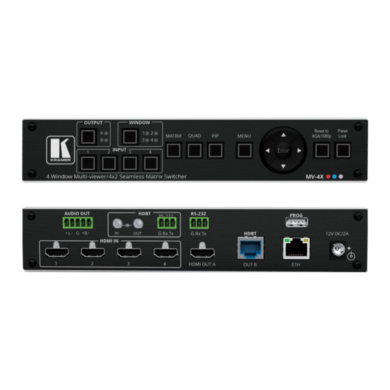
Kramer Electronics Ltd. Connecting MV-4X Always switch off the power to each device before connecting it to your MV-4X. After connecting your MV-4X, connect its power and then switch on the power to each device. Figure 3: Connecting to the MV-4X Rear Panel... -
Page 11: Connecting The Output To A Balanced/Unbalanced Stereo Audio Acceptor
Figure 4: Connecting to a Balanced Stereo Audio Figure 5: Connecting to an Unbalanced Stereo Audio Acceptor Acceptor Connecting to MV-4X via RS-232 You can connect to MV-4X via an RS-232 connection using, for example, a PC. MV-4X features an RS-232 3-pin terminal block connector allowing the RS-232 to control MV-4X. -
Page 12: Operating And Controlling Mv-4X
14. • Setting up the Picture Parameters on page 14. • Defining the Audio Output Settings on page 15. • Setting the Input EDID on page 15. • Configuring HDCP Mode on page 16. MV-4X – Operating and Controlling MV-4X... - Page 13 Auto mode when there are 2 active sources. Auto Layout 3 Select the preferred window PoP Side or PoP Bottom arrangement to use in Auto mode when there are 3 active sources. MV-4X – Operating and Controlling MV-4X...
- Page 14 To set the window layout mode: 1. On the front panel press MENU. The menu appears. 2. Click Window Layout. 3. Select an input: ▪ When in Matrix mode, select an input and perform the following actions: MV-4X – Operating and Controlling MV-4X...
- Page 15 Mirror Select Yes to flip the currently selected input No (default), Yes horizontally. (Horizontal) Border On/Off Enable or disable the color border around On, Off (default) the currently selected window. MV-4X – Operating and Controlling MV-4X...
- Page 16 Chroma key is now configured. Setting up the Picture Parameters MV-4X enables setting the image parameters. To set the picture parameters: 1. On the front panel press MENU. The menu appears. MV-4X – Operating and Controlling MV-4X...
- Page 17 EDID to all the inputs at once or to each input separately. User EDID can be uploaded via the PROG USB port using a memory stick. To set the EDID parameters 1. On the front panel press MENU. The menu appears. MV-4X – Operating and Controlling MV-4X...
- Page 18 Select the HDCP behavior for each input. Off, On (default) Select Off to disable HDCP support on the selected input. OUT A/OUT B Set the HDMI output to follow Input or Output. Follow Output (default), Follow Input HDCP is configured. MV-4X – Operating and Controlling MV-4X...
- Page 19 OSD menu (10 means fully transparency). Background Set the color of the background of the Black, Gray (default), Cyan OSD menu. Text Color Set the OSD text color White (default), Yellow, Magenta OSD parameters are set. MV-4X – Operating and Controlling MV-4X...
- Page 20 8-bit *.BMP format with a resolution of 1920×1080. • Select Yes. • Insert the USB memory stick into the PROG USB port on the rear panel. The 4K logo stored in the memory stick uploads automatically. MV-4X – Operating and Controlling MV-4X...
- Page 21 IP Address (Static Mode) Set the IP address. x.x.x.x (192.168.1.39 default) Subnet Mask (Static Mode) Set the subnet mask. x.x.x.x (255.255.0.0 default) Gateway (Static Mode) Set the gateway. x.x.x.x (192.168.0.1 default] Network parameters are defined. MV-4X – Operating and Controlling MV-4X...
- Page 22 Set auto switching status for output A/B: Off (default), Auto Scan, Last Connected Select Off for manual switching. Select Auto Scan to switch a valid input when no signal is found on the selected input. MV-4X – Operating and Controlling MV-4X...
-
Page 23: Operating Via Ethernet
Ethernet Port via a Network Hub on page 24). Note: If you want to connect via a router and your IT system is based on IPv6, speak to your IT department for specific installation instructions. MV-4X – Operating and Controlling MV-4X... - Page 24 4. Highlight either Internet Protocol Version 6 (TCP/IPv6) or Internet Protocol Version 4 (TCP/IPv4) depending on the requirements of your IT system. 5. Click Properties. The Internet Protocol Properties window relevant to your IT system appears as shown in Figure 7 Figure MV-4X – Operating and Controlling MV-4X...
- Page 25 6. Select Use the following IP Address for static IP addressing and fill in the details as shown in Figure For TCP/IPv4 you can use any IP address in the range 192.168.1.1 to 192.168.1.255 (excluding 192.168.1.39) that is provided by your IT department. MV-4X – Operating and Controlling MV-4X...
- Page 26 8. Click Close. Connecting Ethernet Port via a Network Hub or Switch You can connect the Ethernet port of MV-4X to the Ethernet port on a network hub or using a straight-through cable with RJ-45 connectors. MV-4X – Operating and Controlling MV-4X...
-
Page 27: Using Embedded Web Pages
Kramer Electronics Ltd. Using Embedded Web Pages MV-4X enables you to configure settings via Ethernet using built-in, user-friendly web pages. The Web pages are accessed using a Web browser and an Ethernet connection. You can also configure MV-4X via Protocol 3000 commands (see... - Page 28 Defining MV-4X User Access on page 47. • Defining Advanced Settings on page 48. • Defining OSD Settings on page 51. • Configuring a Logo on page 52. • Viewing the About Page on page 54. MV-4X – Using Embedded Web Pages...
-
Page 29: General Operation Settings
Set the different operation mode parameters via the tabs in the AV Settings page, as described in the following sections. Once defined, use the Active Mode drop-down box on the top right to select the operation mode to output to the acceptors. Figure 12:Selecting the Active Mode MV-4X – Using Embedded Web Pages... - Page 30 Mirror the image horizontally (green). ▪ Apply a Border to the image (green). ▪ Set the Border color of the image from the drop-down box. ▪ Rotate each input image independently by 90, 180 or 270 degrees. MV-4X – Using Embedded Web Pages...
- Page 31 If you need to make identical adjustments for all the inputs, check Apply adjustments to all inputs and adjust the video parameters on that input only. These parameters then apply to the other inputs. ▪ If required, reset adjustments to default settings. Inputs are adjusted. MV-4X – Using Embedded Web Pages...
- Page 32 5. Mute/unmute each output. 6. Select the auto switching mode (Off-Manual, Auto Scan or Last Connected). 7. Select audio source from HDMI or DVI (analog audio source). 8. Select the output resolution from the drop-down list. MV-4X – Using Embedded Web Pages...
-
Page 33: Defining The Matrix Mode Parameters
Once defined, you can set the Matrix mode to the active mode. Switching an input to an output A green indication light next to an input or output indicates that an active signal is present on these ports. MV-4X – Using Embedded Web Pages... - Page 34 2. From the top menu bar, select Matrix. The Matrix page appears and the gray indication to the right of the Matrix mode turns green. Figure 16: AV Settings Page – Matrix Mode Settings 3. Enable input Fade in & Out, using the slider on the side. MV-4X – Using Embedded Web Pages...
- Page 35 Click TEST to check the Chroma Key settings on the display. ▪ If required, click REVERT to revert settings to their default values. ▪ Click SAVE when results are satisfactory. Chroma Key is set. MV-4X – Using Embedded Web Pages...
-
Page 36: Defining The Multi-View Parameters
2. From the top menu bar, select Multi View. 3. Select the Quad mode. The Quad mode view appears and the gray indication to the right of the Multi View mode turns green. Figure 18: Multi View Tab – Quad Mode MV-4X – Using Embedded Web Pages... - Page 37 For each window select the video source and set window parameters. To set the inputs and outputs in the PoP mode see: • Adjusting Input Parameters on page 28. MV-4X – Using Embedded Web Pages...
- Page 38 Next to Size, define the size of the window and then click ▪ Set the position of the window by entering its exact location (H and V), by aligning it to a display side and clicking , or by simply clicking and dragging a window. MV-4X – Using Embedded Web Pages...
- Page 39 16). 2. From the top menu bar, select Multi View. 3. Select the PiP mode. The PiP mode view appears and the gray indication to the right of the Multi View mode turns green. MV-4X – Using Embedded Web Pages...
- Page 40 Figure 23: PםP Mode – Setting the Position of a Window ▪ Mirror the image horizontally using the Mirror slider. ▪ Enable a border around the window using the Border slider. ▪ Select the Border Color from the drop-down box. MV-4X – Using Embedded Web Pages...
- Page 41 Multi View mode turns green. Figure 24: Multi View Tab – Preset Mode 4. For each window you can: ▪ Set Display slider to enable the display of the selected window. ▪ Select the video source. MV-4X – Using Embedded Web Pages...
-
Page 42: Defining The Auto-Layout Parameters
The Auto Layout operation mode becomes active automatically and the defined layout is viewed immediately when the number of the of active sources changes. To set the inputs and outputs mode see: • Adjusting Input Parameters on page 28. • Adjusting Output Parameters on page 30. MV-4X – Using Embedded Web Pages... -
Page 43: Managing Edid
EDIDs that can be assigned to all inputs at the same time, or to each input independently. When a new EDID is read to an input, you may view a brief blink on the output. MV-4X – Using Embedded Web Pages... - Page 44 2. Under STEP 1: SELECT SOURCE, click the required EDID source from the default EDID options, the outputs, or select one of the User uploaded EDID configuration files (for example, the default EDID file). Figure 28: Selecting the EDID Source MV-4X – Using Embedded Web Pages...
- Page 45 The EDID file is uploaded to the User. In some cases, an uploaded EDID may cause compatibility issues with certain sources. If this happens, we recommended that you copy a default EDID to the input. MV-4X – Using Embedded Web Pages...
-
Page 46: Defining General Settings
1. In the Navigation Pane, click Device Settings. The General tab in the Device Settings page appears. Figure 31: MV-4X Device Settings – General 2. Next to Device Name, enter the new device name (Max. 14 characters). 3. Click SAVE. - Page 47 To restart/reset the device: 1. In the navigation bar, click the Device Settings tab. The Device General Settings page appears (Figure 31). 2. Click RESTART/RESET. Figure 32: Restart/Reset the Device 3. Click OK. The device restarts/resets. MV-4X – Using Embedded Web Pages...
-
Page 48: Defining Interface Settings
This requires entering mask and gateway addresses. ▪ Mask Address – Enter subnet mask. Gateway address – Enter the gateway address. ▪ 4. Define TCP (default, 5000) and UDP (default, 50000) ports. Interface settings are defined. MV-4X – Using Embedded Web Pages... -
Page 49: Defining Mv-4X User Access
Figure 34: Device Settings – Users Tab 3. Click On next to Security Status to enable web page authentication (Off by default). Figure 35: Security Tab – Security On 4. Click SAVE. Security is enabled and access requires authentication. MV-4X – Using Embedded Web Pages... -
Page 50: Defining Advanced Settings
7. Click SAVE. Password has changed. Defining Advanced Settings This section describes the following actions: • Defining Auto Sync Mode on page 49. • Enabling HDR on page 50. • View System Status on page 50. MV-4X – Using Embedded Web Pages... - Page 51 1. In the Navigation pane, click Advanced. The Advanced page appears. Figure 37: Advanced Page 2. In the Auto Sync Off drop-down box, select the sync mode (Off, Slow, Fast or Immediate). Auto Sync Off mode is set. MV-4X – Using Embedded Web Pages...
- Page 52 To view system status: 1. In the Navigation pane, click Advanced. The Advanced page appears. 2. In System Status area, view temperature indicators. System status is viewed. MV-4X – Using Embedded Web Pages...
-
Page 53: Defining Osd Settings
Select the menu background color to Black, Gray or Cyan. ▪ Define information display status to On or off, or after a setting change (Info). ▪ Select menu text color to White, Magenta or Yellow. OSD menu parameters are defined. MV-4X – Using Embedded Web Pages... -
Page 54: Configuring A Logo
To define OSD logo settings: 1. In the Navigation pane, click OSD Settings. The General tab in the OSD Settings page appears. 2. Select the Logo tab. The Logo tab appears. Figure 39: Configuring the Logo MV-4X – Using Embedded Web Pages... - Page 55 Boot VGA Source – When the output resolution is set to VGA or less, select Default ▪ to display the default the default graphic image upon booting, or select User to upload a graphic. MV-4X – Using Embedded Web Pages...
-
Page 56: Viewing The About Page
▪ Click RESET to remove the current boot logo. Boot logos are defined. Viewing the About Page View the firmware version and Kramer Electronics Ltd details in the About page. Figure 40: About Page MV-4X – Using Embedded Web Pages... -
Page 57: Technical Specifications
Shipping Dimensions (W, D, H) 39.4cm x 29.6cm x 9.1cm (15.5" x 11.6" x 3.6") Net Weight 1.29kg (2.8lbs) Shipping Weight 1.84kg (4lbs) approx. Accessories Included Power cord and adapter Specifications are subject to change without notice at www.kramerav.com MV-4X – Technical Specifications... -
Page 58: Default Communication Parameters
Native/preferred timing.. 3840x2160p at 60Hz (16:9) Modeline...."3840x2160" 594.000 3840 4016 4104 4400 2160 2168 2178 2250 +hsync +vsync Detailed timing #1..1920x1080p at 60Hz (16:9) Modeline...."1920x1080" 148.500 1920 2008 2052 2200 1080 1084 1089 1125 +hsync +vsync MV-4X – Technical Specifications... - Page 59 CEC physical address..1.0.0.0 Supports AI (ACP, ISRC).. No Supports 48bpp... Yes Supports 36bpp... Yes Supports 30bpp... Yes Supports YCbCr 4:4:4..Yes Supports dual-link DVI... No Maximum TMDS clock..300MHz Audio/video latency (p).. n/a Audio/video latency (i).. n/a MV-4X – Technical Specifications...
- Page 60 Maximum TMDS clock..35MHz YCbCr 4:2:0 capability map data Data payload..... 0F000003 Report information Date generated... 16/06/2022 Software revision..2.91.0.1043 Data source....Real-time 0x0041 Operating system..10.0.19042.2 Raw data 00,FF,FF,FF,FF,FF,FF,00,2D,B2,0D,06,31,00,00,00,06,1C,01,03,80,1F,11,8C,C2,90,20,9C,54,50,8F,26, 21,52,56,2F,CF,00,A9,40,81,80,90,40,D1,C0,31,59,45,59,61,59,81,99,08,E8,00,30,F2,70,5A,80,B0,58, 8A,00,BA,88,21,00,00,1E,02,3A,80,18,71,38,2D,40,58,2C,45,00,BA,88,21,00,00,1E,00,00,00,FC,00,4D, 56,2D,34,58,0A,20,20,20,20,20,20,20,00,00,00,FD,00,17,3D,0F,88,3C,00,0A,20,20,20,20,20,20,01,38, 02,03,3B,F0,52,10,1F,04,13,05,14,02,11,06,15,22,21,20,5D,5E,5F,60,61,23,09,07,07,83,01,00,00,6E, 03,0C,00,10,00,78,3C,20,00,80,01,02,03,04,67,D8,5D,C4,01,78,80,07,E4,0F,00,00,03,9A,29,A0,D0,51, 84,22,30,50,98,36,00,10,0A,00,00,00,1C,66,21,56,AA,51,00,1E,30,46,8F,33,00,10,09,00,00,00,1E,28, 3C,80,A0,70,B0,23,40,30,20,36,00,10,0A,00,00,00,1A,00,00,00,00,00,00,00,00,00,00,00,00,00,00,E0 MV-4X – Technical Specifications...
-
Page 61: Protocol 3000
(<…>) and must be separated by a period (.). The command framing varies according to how you interface with MV-4X. The following figure displays how the # command is framed using terminal communication software (such as Hercules): MV-4X –... -
Page 62: Protocol 3000 Commands
(refer to device definitions). In devices that enable showing multiple outputs on one display – each in a separate window – this command relates only to the window associated with the output indicated in the out- index parameter. MV-4X – Protocol 3000... - Page 63 #FACTORY<CR> default configuration: #FACTORY<CR> FEEDBACK This command deletes all ~nn@FACTORYok<CR><LF> user data from the device. The deletion can take some time. Your device may require powering off and powering on for the changes to take effect. MV-4X – Protocol 3000...
- Page 64 FEEDBACK 2 – Win 2 ~nn@IMAGE-PROPP1,mode<CR><LF> 3 – Win 3 4 – Win 4 – Status mode 0 – Full 1 – 16:9 2 – 16:10 3 – 4:3 4 – Best Fit 5 – User MV-4X – Protocol 3000...
- Page 65 Get DHCP mode for port: 0 – Static #NET-DHCP?<CR> #NET-DHCP?<CR> 1 – DHCP For Backward compatibility, FEEDBACK parameter can be ~nn@NET-DHCPmode<CR><LF> omitted. In this case, the Network ID, by default, is 0, which is the Ethernet control port. MV-4X – Protocol 3000...
- Page 66 3 – IN 3 4 – IN 4 angle – For inputs: 0 – Off 1 – 90 degrees to the left 2 – 90 degrees to the right 3 – 180 degrees 4 – Mirror MV-4X – Protocol 3000...
- Page 67 FEEDBACK ~nn@STANDBYvalue<CR><LF> – On/Off value UPDATE-EDID Upload the User EDID COMMAND Upload EDID to User 2: 1 – User 1 #UPDATE-EDIDedid_user<CR> #UPDATE-EDID2<CR> 2 – User 2 FEEDBACK 3 – User 3 ~nn@UPDATE-EDIDedid_user<CR><LF> 4 – User 4 MV-4X – Protocol 3000...
- Page 68 6=848X480P@60Hz, 7=1024X768P@60Hz, 8=1280X720P@50Hz, 9=1280X720P@60Hz, 10=1280X768P@60Hz, 11=1280X800P@60Hz, 12=1280X960P@60Hz, 13=1280X1024P@60Hz, 14=1360X768P@60Hz, 15=1366X768P@60Hz, 16=1400X1050P@60Hz, 17=1440X900P@60Hz, 18=1600X900P@60RBHz, 19=1600X1200P@60Hz, 20=1680X1050P@60Hz, 21=1920X1080P@24Hz, 22=1920X1080P@25Hz, 23=1920X1080P@30Hz, 24=1920X1080P@50Hz, 25=1920X1080P@60Hz, 26=1920X1200P@60HzRB, 27=2048X1152P@60HzRB, 28=3840X2160P@24Hz, 29=3840X2160P@25Hz, 30=3840X2160P@30Hz, 31=4096X2160P@24Hz, 32=4096X2160P@25Hz, 33=R4096X2160P@30Hz, 34=4096X2160P@50Hz, 35=4096X2160P@59Hz, 36=4096X2160P@60Hz, 37=3840X2160P@50Hz, 38=3840X2160P@59Hz, 39=3840X2160P@60Hz, 40=3840X2400P@60Hz RB MV-4X – Protocol 3000...
- Page 69 7 – Cyan value (refer to device 8 – White definitions). 9 – Dark Red 10 – Dark Green 11 – Dark Blue 12 – Dark Yellow 13 – Dark Magenta 14 – Dark Cyan 15 – Gray MV-4X – Protocol 3000...
- Page 70 Enable/disable window border. COMMAND Enable window 1 border: #WND-BRDwin_num,enable<CR> border: #WND-BRD1,1<CR> 1 – Win 1 FEEDBACK 2 – Win 2 ~nn@WND-BRDwin_num,enable<CR><LF> 3 – Win 3 4 – Win 4 – value 0 – Disable 1 – Enable MV-4X – Protocol 3000...
- Page 71 Set window 1 V sharpness #W-SHARP-Vwin_num,value<CR> value to 20: vertical sharpness 1 – Win 1 #W-SHARPNESS- FEEDBACK H1,20<CR> 2 – Win 2 ~nn@W-SHARP-Vwin_num,value<CR><LF> 3 – Win 3 4 – Win 4 – V sharpness value:0-100 value MV-4X – Protocol 3000...
- Page 72 2 – Win 2 ~nn@W-SRCwin_num,src<CR><LF> 3 – Win 3 4 – Win 4 – Input source to connect to window 1 – HDMI 1 2 – HDMI 2 3 – HDMI 3 4 – HDMI 4 MV-4X – Protocol 3000...
-
Page 73: Result And Error Codes
(Reserved) ERR_RESERVED_8 (Reserved) ERR_RESERVED_9 (Reserved) ERR_RESERVED_10 (Reserved) ERR_RESERVED_11 (Reserved) ERR_RESERVED_12 (Reserved) ERR_EDID_CORRUPTED EDID corrupted ERR_NON_LISTED Device specific errors File has the same CRC – not changed ERR_SAME_CRC ERR_WRONG_MODE Wrong operation mode ERR_NOT_CONFIGURED Device/chip was not initialized MV-4X – Protocol 3000... - Page 74 This limited warranty gives you specific legal rights, and you may have other rights which vary from country to country or state to state. This limited warranty is void if (i) the label bearing the serial number of this product has been removed or defaced, (ii) the product is not distributed by Kramer Electronics or (iii) this product is not purchased from an authorized Kramer Electronics reseller.
- Page 75 SAFETY WARNING Disconnect the unit from the power supply before opening and servicing For the latest information on our products and a list of Kramer distributors, visit our website where updates to this user manual may be found. We welcome your questions, comments, and feedback.
Need help?
Do you have a question about the MV-4X and is the answer not in the manual?
Questions and answers