
Related Manuals for Kramer VP-778


Summary of Contents for Kramer VP-778
- Page 1 USER MANUAL MODEL: VP-778 Presentation Matrix Switcher/Dual Scaler P/N: 2900-300445 Rev 1 www.Kramerav.com...
-
Page 6: Table Of Contents
Recycling Kramer Products Overview HDCP Compliance for HDMI inputs About HDBaseT™ Technology Using Twisted Pair Cable Defining the VP-778 Presentation Matrix Switcher/Dual Scaler Installing in a Rack Connecting the VP-778 Wiring the RJ-45 Connectors Connecting the Balanced Stereo Audio Line Output... - Page 7 Kramer Protocol 3000 Syntax 14.7 Protocol 3000 Commands Figures Figure 1: VP-778 Presentation Matrix Switcher/Dual Scaler Front Panel Figure 2: VP-778 Presentation Matrix Switcher/Dual Scaler Rear Panel Figure 3: Connecting the VP-778 Presentation Matrix Switcher/Dual Scaler Figure 4: TP PINOUT...
- Page 8 Figure 52: Port Tunneling Figure 53: Firmware Upgrade – list of Files to Upgrade Figure 54: Firmware Upgrade – Upgrade Process Figure 55: Firmware Upgrade – Upgrade Complete Figure 56: Firmware Upgrade – list of Files to Rollback VP-778 – Contents...
-
Page 9: Introduction
Introduction Welcome to Kramer Electronics! Since 1981, Kramer Electronics has been providing a world of unique, creative, and affordable solutions to the vast range of problems that confront video, audio, presentation, and broadcasting professionals on a daily basis. In recent years, we have redesigned and upgraded most of our... -
Page 10: Getting Started
Avoid interference from neighboring electrical appliances that may adversely influence signal quality Position your VP-778 away from moisture, excessive sunlight and dust This equipment is to be used only inside a building. It may only be connected to other equipment that is installed inside a building. -
Page 11: Recycling Kramer Products
Kramer Electronics has made arrangements with the European Advanced Recycling Network (EARN) and will cover any costs of treatment, recycling and recovery of waste Kramer Electronics branded equipment on arrival at the EARN facility. For details of Kramer’s recycling arrangements in your particular country go to our recycling pages at www.kramerav.com/support/recycling. -
Page 12: Overview
Overview VP-778 is an 8 Input ProScale™ Presentation Matrix Switcher/Dual Scaler with seamless video cuts and 4K30 UHD output support. VP-778 can be configured as a single 4K output (4K@30 UHD (3840x2160)) or dual HD scaler with full PIP capabilities. - Page 13 (2.25Gbps per graphic channel) System range (HDBaseT) – Up to 130m (430ft) normal mode; up to 180m (590ft) in ultra-mode (1080p @60Hz @24bpp) when using Kramer cables. For optimum range and performance use the recommended Kramer cables available at www.kramerav.com/product/VP-778.
- Page 14 By RS-232 serial commands transmitted by a touch screen system, PC, or other serial controller The VP-778 is housed in a 19” 1U rack mountable enclosure, with handles and rack ears included, and is fed from a 100-240 VAC universal switching power supply.
-
Page 15: Hdcp Compliance For Hdmi Inputs
If an HDMI signal is HDCP protected, it can only appear on HDMI outputs that are connected to HDCP compliant displays. The VP-778 will not output a picture on an HDMI display that is not HDCP compliant; instead it will show a green screen. -
Page 16: Figure 1: Vp-778 Presentation Matrix Switcher/Dual Scaler Front Panel
Figure 1: VP-778 Presentation Matrix Switcher/Dual Scaler Front Panel Feature Function IR LED Lights red when the unit accepts IR remote commands IR Receiver Accepts IR remote commands MODE Button Select the operation mode: audio follow video (AFV), Video or audio... - Page 17 Feature Function Button// Section 6 Navigation Press to move to the previous level in the OSD screen (see ). When not within the OSD menu, press to decrease the Buttons VOLUME Audio CH1 volume Button Button // Section ...
-
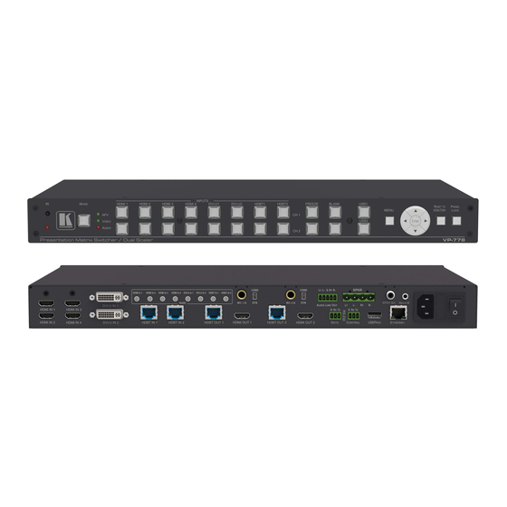
Page 18: Figure 2: Vp-778 Presentation Matrix Switcher/Dual Scaler Rear Panel
DVI-U IN Connectors Connect to the video source that can be HDMI, VGA, Component or Composite video (from 1 to 2) Connect to an HDBT Transmitter (for example, the Kramer TP-580Txr) to pass audio and video HDBT IN Connectors signals as well as serial commands (from 1 to 2) AUDIO HDMI IN 3.5mm Mini Jack... - Page 19 Feature Function Channel 1 output HDBT OUT 1 RJ-45 Connect to an HDBT receiver (for example, Kramer TP-580Rxr) to pass Ethernet, audio and video connectors signals, as well as serial commands HDMI OUT 1 Connect to an HDMI acceptor Channel 2 Output...
-
Page 20: Installing In A Rack
Installing in a Rack This section provides instructions for rack mounting the unit. VP-778 - Installing in a Rack... -
Page 21: Connecting The
Alternatively, you can connect the DVI connector on the DVD player to the HDMI connector on the VP-778 via a DVI-HDMI adaptor. You can connect the audio signal via the AUDIO IN HDMI 3.5mm mini jack, or use the embedded audio 2. - Page 22 RS-232 CONTROL terminal block connectors (see RS-232 DATA terminal block connectors for sending RS-232 Section 8 commands via HDBT (see Section 8 Ethernet connector (see 12. Connect the power cord (not shown in Figure VP-778 - Connecting the VP-778...
-
Page 23: Figure 3: Connecting The Vp-778 Presentation Matrix Switcher/Dual Scaler
Figure 3: Connecting the VP-778 Presentation Matrix Switcher/Dual Scaler VP-778 - Connecting the VP-778... -
Page 24: Wiring The Rj-45 Connectors
This section defines the TP pinout, using a straight pin-to-pin cable with RJ-45 connectors. Figure 4: TP PINOUT EIA /TIA 568B Wire Color Orange / White Orange Green / White Blue Blue / White Green Brown / White Brown VP-778 - Connecting the VP-778... -
Page 25: Connecting The Balanced Stereo Audio Line Output
Microphone Pinout This section defines the microphone pinout. The microphone 6mm jack pinout for a condenser microphone. Figure 7: Condenser Microphone Pinout The microphone 6mm jack pinout for a dynamic microphone. Figure 8: Dynamic Microphone Pinout VP-778 - Connecting the VP-778... -
Page 26: Osd Menu
OSD Menu The OSD menu lets you set the VP-778 operation parameters. Note that the OSD appears only on the CH 2 output in the Overlay mode. The OSD sub-menu operations appear in the OSD title, as shown in the example in Section ... - Page 27 (Scale in this example) After selecting Output (which is the second Level), it appears in the subtitle The subtitle shows the current, Level 3, selection and the menu list shows the function (HDMI2) VP-778 - OSD Menu...
- Page 28 Data is saved per window and per input (to a dedicated input + window memory), as applicable The control buttons let you control the VP-778 via the OSD menu. Press the: MENU (or ) button to enter the menu, exit the menu, and when in the OSD menu, move to the previous level and change menu settings in the OSD screen.
-
Page 29: Inputs Menu
HDMI/HDBT input Color Space Select the color space for each input to RGB, YPbPr or Follow Input Volume Slide the progress bar to set the audio level for each input VP-778 - OSD Menu... -
Page 30: Layout Menu
1920x1200@60RB, 480p60, 576p50, 720p50, 720p59.94, 720p60, 1080i50, 1080i60, 1080p23.976, 1080p24, 1080p25, 1080p29.97, 1080p30, 1080p50, 1080p59.94, 1080p60, 2k50, 2k60, 4k2k30 Note that setting the output resolution to 4k2k30 will automatically change the window settings to Single Window in the Overlay mode. VP-778 - OSD Menu... - Page 31 By setting the output resolution to Native, the VP-778 is triggered to read the EDID of the main display and change the output resolution value according to the native resolution of the display.
-
Page 32: Channel 1 / Channel 2 Menus
Zoom Shift Mode > Auto) Window Slide the progress bar to set the H position and Width, V position and Width which will Customization appear when selecting Customized Single/Dual in Layout>Overlay Settings, see Section 6 .3 VP-778 - OSD Menu... - Page 33 Slide the progress bar to set the Mosquito NR Mosquito NR The higher the level, the stronger the filtering of the image Slide the progress bar to set the Combing NR Combing NR Improves the quality of the subtitles VP-778 - OSD Menu...
- Page 34 This is useful, for example, when the output is connected to a projector, and the projector will automatically shut down when it has no input. Press any front panel button or key on the IR remote control transmitter to exit the Sync Off mode VP-778 - OSD Menu...
- Page 35 Set to pass-through to On to pass the input audio to the output or set Pass-Through to Off. Section 6 Mic Effect For Channel 1 only (see .4.1) Note that the audio settings do not apply for Channel 2 when in the Overlay mode VP-778 - OSD Menu...
-
Page 36: Figure 12: Talkover Mode
Mic Volume Slide the progress bar to set the Mic volume Mic Delay Slide the progress bar to set the microphone delay time: 1 to 40ms Mic Mute Set to On or Off Figure 12: Talkover Mode VP-778 - OSD Menu... - Page 37 Selecting the Correct Aspect Ratio You can configure the aspect ratio of any output image to fit your application. The VP-778 offers four different aspect ratio settings: Follow Input, Follow Output, Best Fit and Letterbox. Here is how each of these settings works.
-
Page 38: Figure 13: Changing The Size Of The Window
The following example shows how to increase the width of the window Figure 14: Increasing the Width 4. Select V Height (an OSD slide bar appears) and press + to increase the height, or – to decrease the height, see Figure VP-778 - OSD Menu... -
Page 39: Figure 15: Increasing The Height
Use the H Position and V Position items in the OSD to change the position of the window using the + and – buttons on the front panel or remote control transmitter (as illustrated in Figure 16). Figure 16: Positioning the Window VP-778 - OSD Menu... -
Page 40: Figure 17: Window Customization
1. Check that window control is set as required (for example, PiP Window Control). 2. Select Window Customization. The following Window appears: Figure 17: Window Customization 3. To move the picture to the right, select H Position. An OSD slide bar appears: Figure 18: H-Position Slide Bar VP-778 - OSD Menu... -
Page 41: Misc Menu
The sequence in which you change the size and position of the window is insignificant, as long as you make sure that the resized image does not go beyond the window boundaries. Misc Menu Figure 20: Misc Menu VP-778 - OSD Menu... - Page 42 Disconnect all the port tunneling connections Power Set the power amplifier (SPKR OUT) level to Off or to levels 1 to 4 Amplifier This submenu item is specific for the power amplifier on top of the general volume level VP-778 - OSD Menu...
- Page 43 The factory reset process takes up to 3 minutes in which all the front panel button lights turn off (except for the PANEL LOCK button) and then turn on again; the image on the displays reappears and only then you can turn the machine off if required VP-778 - OSD Menu...
- Page 44 Channel 1 window show through. To use this feature it is recommended to set the Channel 2 image as follows: use low-luminance colors for the background (the key image portion) and high-luminance colors for the logo. VP-778 - OSD Menu...
-
Page 45: Layout
In the transition mode you can setup the input, view it via the Channel 2 output and then switch it to the Channel 1 output. The VP-778 has two output channels (Channel 1 and Channel 2). Each channel includes an HDMI connector and an HDBT port: Each of these channels functions independently. - Page 46 3. Define the transition settings: Speed, Mode, Effect and Direction. 4. Press the desired CH 2 INPUT front panel button. 5. Press ENTER to carry out the transition. To set the channel 1 input, repeat the above procedures using the Channel 2 menu. VP-778 - VP-778 Layout...
-
Page 47: Overlay Mode
In this case the PiP and Main windows appear as set in Channel 1/2>Advanced>No Signal?>Gray/Blue/Black. The preset PiP configurations are available: Picture-in-Picture, with a smaller PiP window superimposed over a full main window image VP-778 - VP-778 Layout... - Page 48 To set the PiP window in the Overlay mode: 1. In the Layout menu select Overlay Settings. When in the Overlay display mode 2. Select the type of image you want displayed: Picture in Picture, Picture + Picture, Split or Single Window. VP-778 - VP-778 Layout...
-
Page 49: Figure 21: Vga Superimposed Over Hdmi
4. In the Channel 1/Channel 2 menu, select Source. 5. Select an input (from 1 to 8). 6. Press the ENTER button. 7. Press the MENU a few times until you exit the OSD menu (changes are saved upon exit). VP-778 - VP-778 Layout... -
Page 50: Controlling The
The infrared remote control transmitter (see Section Controlling via the Front Panel Buttons The VP-778 includes the following front panel buttons: Input selector buttons for selecting the required input: HDMI (1 to 4), DVI-U (1 and 2) and HDBT (1 and 2), see Section 3 .4... - Page 51 An orange button indicates that only the video signal of that input is selected A red button indicates that only the audio signal of that input is selected A dim button indicates an ineffective signal (for all button colors) A dim blue button indicating Auto switching VP-778 - Controlling the VP-778...
- Page 52 HDMI1 and the video remains in HDMI4. Press CH 2 HDBT2 – the audio only switches to HDBT2 and the video remains in HDBT2 so that audio follows video and the button light green VP-778 - Controlling the VP-778...
- Page 53 CH 1 and CH 2 inputs as follows, from: When in the Transition mode, pressing the ENTER front panel button in the Follow mode will switch the CH 1 inputs to follow the CH 2 inputs: VP-778 - Controlling the VP-778...
- Page 54 8.1.3 Button Behavior in the Overlay Mode When in the overlay mode, the VP-778 does not pass the CH 2 audio signal to the output. In the Overlay dual mode the CH 2 audio input button is dimmed: Section 7 When in the Overlay mode, in the Single Window setting (see .2), the...
- Page 55 You can view the command via the Data Display item in the USR KeyPad menu. 3. Launch the USR Keypad command in any of the following ways: Pressing USR 1 on the VP-778 front panel or IR remote control transmitter. Selecting Misc>Advance>USR KeyPad>Launch via Y commands, see Section ...
-
Page 56: Connecting To The Vp-778 Via
RS-232 DATA to pass data to and from the machines that are connected to the HDBT connectors RS-232 CONTROL to control the VP-778 Connect the RS-232 terminal block on the rear panel of the VP-778 to a PC/controller, as follows (see Figure 22): ... -
Page 57: Figure 23: Local Area Connection Properties Window
8.3.1 Connecting the Ethernet Port Directly to a PC You can connect the Ethernet port of the VP-778 directly to the Ethernet port on your PC using a crossover cable with RJ-45 connectors. This type of connection is recommended for identifying the VP-778 with the factory configured default IP address. -
Page 58: Figure 24: Internet Protocol Version 4 Properties Window
Protocol Version 4 (TCP/IPv4) depending on the requirements of your IT system. 5. Click Properties. The Internet Protocol Properties window relevant to your IT system appears as shown in Figure 24 Figure Figure 24: Internet Protocol Version 4 Properties Window VP-778 - Controlling the VP-778... -
Page 59: Figure 25: Internet Protocol Version 6 Properties Window
6. Select Use the following IP Address for static IP addressing and fill in the details as shown in Figure For TCP/IPv4 you can use any IP address in the range 192.168.1.1 to 192.168.1.255 (excluding 192.168.1.39) that is provided by your IT department. VP-778 - Controlling the VP-778... -
Page 60: Controlling Via The Osd Menu
8. Click Close. 8.3.1.1 Connecting the ETHERNET Port via a Network Hub or Switch You can connect the Ethernet port of the VP-778 to the Ethernet port on a network hub or network router, via a straight-through cable with RJ-45 connectors. -
Page 61: Controlling Via The Infrared Remote Control Transmitter
Controlling via the Infrared Remote Control Transmitter You can control the VP-778 from the infrared remote control transmitter: Keys Function POWER Toggle the power save mode ON or OFF RESET Press to reset to the default resolution (toggles between RESET TO XGA and 720p) - Page 62 60 meters when used with three IR extension cables. Before using the external IR receiver, be sure to arrange for your Kramer dealer to insert the internal IR connection cable with the 3.5mm connector that fits into the REMOTE IR opening on the rear panel.
-
Page 63: Using The Embedded Web Pages
Using the Embedded Web Pages The VP-778 can be operated remotely using the embedded web pages. The web pages are accessed using a web browser and an Ethernet connection. Before attempting to connect: Perform the procedures in Section ... -
Page 64: Figure 28: Routing And Scaling Page With Navigation List On Left
Click the arrow to hide the navigation list on the left (note that the page icons remain visible allowing you to select a Web page even if the list is hidden). Click the button to view the Web pages in full screen and click to exit. VP-778 - Using the Embedded Web Pages... -
Page 65: Routing & Scaling The Image
Setting or muting the output volume (see Section .2.7). Functions that are specific to the Transition or Overlay modes are specified in sections and 9 .2.8 .2.9, respectively. VP-778 - Using the Embedded Web Pages... -
Page 66: Figure 29: Routing And Scaling Page
9.2.1 Setting the Operation Mode The Routing & Scaling page enables you to set the VP-778 either to the Transition Section 7 Section 7 mode (see .1) or the Overlay mode (see .2). To set the operation mode: 1. - Page 67 ) to freeze the image or click to set a blank display. To select a test pattern: 1. In the Navigation pane, click Routing & Scaling. The Routing & Scaling page appears: 2. Click a test pattern button. VP-778 - Using the Embedded Web Pages...
-
Page 68: Figure 30: Routing & Scaling Page - Auto Switching Window
2. Click Auto Switching. The following Window Appears: Figure 30: Routing & Scaling Page – Auto Switching Window 3. Open the dropdown list to set the switching mode (Off, Scan or Last Connected). VP-778 - Using the Embedded Web Pages... -
Page 69: Figure 31: Routing & Scaling Page - Scan Mode
4. Select the switching mode (for example, select Scan). The Auto Switching window is enabled: Figure 31: Routing & Scaling Page – Scan Mode 5. Check the inputs that should be active in the scan and uncheck to disable others. VP-778 - Using the Embedded Web Pages... -
Page 70: Figure 32: Routing & Scaling Page - Setting Priorities
The Zoom button lets you zoom the image up to 4000% and shift the image to zoom into a specific area. Note that if there is no active signal on the input, the Zoom window will not open. VP-778 - Using the Embedded Web Pages... -
Page 71: Figure 33: Routing And Scaling Page - Program - Zoom Window
In that case the zoom shift mode will return to Auto mode. The Customized mode in which the zoom and shift are set manually and do not change even if the source/input resolution are changed. VP-778 - Using the Embedded Web Pages... -
Page 72: Figure 34: Routing And Scaling Page - Transition Take
Set the size and the position of the Main and PIP images. Set the layout of the Overlay mode. Set the customized image size. Keep aspect ratio when resizing the image. VP-778 - Using the Embedded Web Pages... -
Page 73: Figure 35: Routing And Scaling Page - Changing The Image Size
1. Click the desired layout button: Single Window, Picture in Picture, Picture + Picture, Split or customized (as defined when setting the size and the position of the image): Figure 36: Routing and Scaling Page – Selecting the Layout VP-778 - Using the Embedded Web Pages... -
Page 74: Figure 37: Routing And Scaling Page - Setting The Layout
For example, setting the Picture in Picture layout results in the following: Figure 37: Routing and Scaling Page – Setting the Layout Setting to customized Dual shows the manually defined images: Figure 38: Routing and Scaling Page – Customized Dual Layout VP-778 - Using the Embedded Web Pages... -
Page 75: Transition Settings Page
.2.1) Set the Transition (see Section .3.1) 9.3.1 Transition effects Set the transition mode type, effect and speed of the transition and then press Take to carry out the transition. VP-778 - Using the Embedded Web Pages... - Page 76 Swap mode: Channel 1 and Channel 2 inputs swap places. 3. Set the transition effect, click cut ( ) or fade ( 4. Set the speed of the transition. 5. Click Take to carry out the transition setup. VP-778 - Using the Embedded Web Pages...
-
Page 77: Audio Settings Page
Set AFV or audio breakaway mode (see Section .4.1). Adjust the Bass, Middle, Treble, balance and Lip Sync (see Section .4.2). Adjust the output volume (see Section .4.3). VP-778 - Using the Embedded Web Pages... -
Page 78: Figure 41: Mic Settings Page
2. Select the Audio tab. 3. Set the source to AFV or to any of the 8 analog inputs. If an analog audio source is selected, the AFV source is disabled and is set to Analog. VP-778 - Using the Embedded Web Pages... - Page 79 3. Set the operation mode to Mix or TalkOver. 9.4.5 Setting the Delay time To set the delay time: 1. In the Navigation pane, click Audio Settings. The Audio Settings page appears. 2. Select the Mic tab. VP-778 - Using the Embedded Web Pages...
- Page 80 3. Use the volume slider on the right side to set the Microphone volume and the Line out volume, and click the speaker button to mute ( ) or unmute ) the audio output. VP-778 - Using the Embedded Web Pages...
-
Page 81: Output Settings Page
Master connection (HDMI 1, HDBT 1, HDMI 2 or HDBT 2) Deep color settings (Follow Output or Off) Color space (RGB, YPbPr422 or YPbPr444) HDCP mode (Follow Input or Follow Output) VP-778 - Using the Embedded Web Pages... -
Page 82: Device Settings Page
Unit name (type the name and click the Set button) Ethernet parameters View the Information and HDBT information windows (see Section 9 .6.2 Section .6.3) Perform factory reset (see Section .6.4) Figure 43: Device Settings Page VP-778 - Using the Embedded Web Pages... -
Page 83: Figure 44: Device Settings Page – Communication Warning
When setting DHCP OFF, the DHCP OFF window lets you select the default IP address or a custom IP address: Figure 45: Device Settings Page – DHCP Window Click Apply to confirm changes. VP-778 - Using the Embedded Web Pages... -
Page 84: Figure 46: Device Settings Page – Dhcp On Notification
Section 1 pages or via the #net-ip? Protocol command (see 4.7.2.4). 9.6.2 Viewing VP-778 Information Click the Information button ( ) to view the device information: Figure 47: Device Settings Page – Info Window VP-778 - Using the Embedded Web Pages... -
Page 85: Figure 48: Device Settings Page – Hdbt Info Window
2. Click Factory Reset. The following message appears: Figure 49: Device Settings Page – Communication Warning 3. Check Include Ethernet if you also want to reset Ethernet parameters to their default value. VP-778 - Using the Embedded Web Pages... -
Page 86: About Page
The following message appears on the screen: Figure 50: Device Settings Page – Factory Reset Message About Page The VP-778 About page lets you view the Web page version and Kramer Electronics Ltd details. Figure 51: About Page VP-778 - Using the Embedded Web Pages... -
Page 87: Port Tunneling
Port Tunneling The port tunneling feature lets you send and receive simple RS-232 signals between a controller and a serial device via the VP-778 which is connected to the Ethernet and outputs via TP cable. The example, illustrated in Figure 52, shows a Kramer room controller that is connected to the VP-778 via the Ethernet. - Page 88 4.2.2. UART protocol 3000 command – see Section 1 4.7.4.2. 3. Make sure that the VP-778 is connected to Ethernet. The VP-778 is now ready to tunnel RS-232 signals via Ethernet port tunneling. VP-778 - Port Tunneling...
-
Page 89: Routing Serial Data
Routing Serial Data The VP-778 lets you route serial data through its various ports in the following ways: Serial matrix – up to eight sets of connections are created for passing serial data from a selected source to a selected destination. -
Page 90: Flash Memory Upgrade
12.1 Firmware Upgrade Process Unzip the firmware files on your desktop to a folder named “VP-778” and then copy that folder to an empty, FAT32-formated USB memory stick (with at least 30Mb of free space) as a root folder. After copying the “VP-778” folder as a single root folder, the USB memory stick is ready to be used by attaching it into the device. -
Page 91: Figure 53: Firmware Upgrade – List Of Files To Upgrade
The OSD shows the firmware version found in the memory stick: Figure 53: Firmware Upgrade – list of Files to Upgrade 3. Click the ENTER button on the front panel. Wait for the completion of the upgrade process: Figure 54: Firmware Upgrade – Upgrade Process VP-778 - Flash Memory Upgrade... -
Page 92: Rollback
1. On the front panel click the MENU button, select FW Upgrade and then Section 6 select Rollback (see .5). The OSD shows the firmware version found in the system: Figure 56: Firmware Upgrade – list of Files to Rollback VP-778 - Flash Memory Upgrade... - Page 93 2. Press the ENTER button or the left arrow to proceed. Wait for completion of the procedure. 3. Reboot the machine by turning it off and then on again. VP-778 - Flash Memory Upgrade...
-
Page 94: Technical Specifications
52.5cm x 33cm x 10.7cm (20.7” x 13” x 4.2”) W, D, H Shipping Dimensions: Weight: 2.6kg (5.7lbs) approx. Shipping Weight: 3.8kg (8.4lbs) approx. Included Accessories: Power cord, rack ears, IR remote control, 2 ADC-DMA/5BF cables. 2 AD-DM/GF adaptors Specifications are subject to change without notice at www.kramerav.com VP-778 - Technical Specifications... -
Page 95: Default Communication Parameters
Factory reset via the Device Settings embedded web page (including or excluding ETH) Including ETH: use Factory Reset command “Including ETH” Protocol 3000: or #Y 0,561,1<CR> Excluding ETH: use Factory Reset command “Excluding ETH” or #Y 0,562,1<CR> VP-778 - Technical Specifications... -
Page 96: Input Resolutions
1024x768_85 1440x900_60 625_P50 1080_P25 800x600_56 1152x864_75 1400x1050_60 720_P24 1080_P30 800x600_60 1280x800_60 1400x1050_75 720_P25 1080_P50 800x600_72 1280x960_85 1600x900_60 720_P30 1080_P60 800x600_75 1280x768_60 1600x1200_60 720_P50 2k50 800x600_85 1280x1024_60 1680x1050_60 720_P60 2k60 848x480_60 1280x1024_75 1920x1200_60RB 1080_I50 640X480_60 1024x768_60 1280x1024_85 VP-778 - Technical Specifications... -
Page 97: Output Resolutions
1920x1200@60 1080p50 800x600@50 1280x1024@75 480p60 1080p59.94 800x600@60 1360x768@60 576p50 1080p60 800x600@75 1366x768@50 720p50 1080i50 1024x768@50 1366x768@60 720p59.94 1080i60 1024x768@60 1400x1050@50 720p60 2k50 1024x768@75 1400x1050@60 1080p23.976 2k60 1280x768@50 1600x900@60 1080p24 4k2k@30 1280x768@60 1600x1200@50 1080p25 1280x800@60 1600x1200@60 1080p29.97 VP-778 - Technical Specifications... -
Page 98: Rs-232 Communication Protocol
The Kramer Protocol lets you control the VP-778 from any standard terminal ® software (for example, the Windows HyperTerminal Application). 14.1 Using the Communication Protocol There are three different methods to control the VP-778 RS-232 or the Ethernet: Protocol commands mimicking the OSD, see Section 1 4.2 ... - Page 99 Main menu and the 3 item in the Layout Section 6 submenu (see also .1). When navigating in the OSD MENU you will be able to see the Overlay Settings valid parameters. VP-778 - VP-778 RS-232 Communication Protocol...
- Page 100 720p60 1080p50 1080p60 (default) 2k50 2k60 Color Depth 12 BPP 1x22 8 BPP Modeline Multiple Modeline 1x23 Single Modeline Audio Channels 1x24 Stereo HDCP Mode Color Space YPbPr Follow Input Volume <progress bar> [-80:+20] VP-778 - VP-778 RS-232 Communication Protocol...
- Page 101 Video Resolution NATIVE 640x480p60 640x480p75 800x600p50 800x600p50 800x600p75 1024x768p50 1024x768p60 1024x768p75 1280x768p50 1280x768p60 1280x800p60 1280x1024p50 1280x1024p60 1280x1024p75 1360x768p60 1366x768p50 1366x768p60 1400x1050p50 1400x1050p60 1600x900p60 1600x1200p50 1600x1200p60 1680x1050p60 1920x1200p60RB 480p60 576p50 720p50 720p59_94 720p60 1080p23_976 1080p24 VP-778 - VP-778 RS-232 Communication Protocol...
- Page 102 Range Func. Notes 1080p25 1080p29_97 1080p30 1080p50 1080p59_94 1080p60 1080i50 1080i60 2k50 2k60 4k2k30 Master HDMI1 Connection HDBT1 HDMI2 HDBT2 Deep Color Follow Output Color Space YPbPr422 YPbPr444 HDCP Mode Follow Output Follow Input VP-778 - VP-778 RS-232 Communication Protocol...
- Page 103 9300K Gamma Mode Gamma Off Gamma 0.4 Gamma 0.8 Gamma 1.2 354/454 Gamma 1.6 Gamma 2.0 Gamma 2.4 Gamma 2.8 Color Correction <progress bar> [0:4] 355/455 Blue Color Correction <progress bar> [0:4] 356/456 Green VP-778 - VP-778 RS-232 Communication Protocol...
- Page 104 <countdown 3832/4832 action> Test Pattern 384/484 Slide Bar Color Bar No Signal Gray 385/485 Blue Black Fade-Thru Black 386/486 Freeze Auto Switching Mode 3871/4871 Scan Mode Last Connected Priority see Priority Commands table below VP-778 - VP-778 RS-232 Communication Protocol...
- Page 105 Mic Effect See Audio Mic Effect table below Priority commands 4th Level 5th Level 6th Level 7th Level Range Func. CH1/CH2 Priority Input HDMI1 3872x1/4872x1 HDMI2 HDMI3 HDMI4 DVI-U1 DVI-U2 HDBT1 HDBT2 Active 3872x2/4872x2 VP-778 - VP-778 RS-232 Communication Protocol...
- Page 106 30 Sec 60 Sec Keying Chroma Keying Red <progress bar> [0:240] Chroma Keying <progress bar> [0:240] Green Chroma Keying Blue <progress bar> [0:240] Chroma Keying Luma Keying Upgrade <action Upgrade screen> Rollback <action screen> VP-778 - VP-778 RS-232 Communication Protocol...
- Page 107 5535 screen> Power Amplifier Power Level 1 Power Level 2 Power Level 3 Power Level 4 USR KeyPad USR1 / USR2 Baudrate 1200 555x1 2400 4800 9600 19200 92400 57600 115200 Data Bits 555x2 VP-778 - VP-778 RS-232 Communication Protocol...
- Page 108 Mark Space Stop Bits 555x4 Destination Port Tunneling 555x5 DATA HDBT-IN1 HDBT-IN2 HDBT-OUT1 HDBT-OUT2 None <action Data Display 555x6 screen> Launch <action 555x7 screen> <action Factory Reset Including ETH screen> Excluding ETH <action screen> VP-778 - VP-778 RS-232 Communication Protocol...
-
Page 109: Protocol Table: Mimicking Remote And Front Panel Buttons
RIGHT KEYCODE KEYCODE PROG KEYCODE PREV RESET KEYCODE KEYCODE PROG KEYCODE PROG LOCK MUTE KEYCODE PROG KEYCODE PREV USR1 MUTE USR2 KEYCODE PROG KEYCODE POWER KEYCODE KEYCODE PROG MODE KEYCODE KEYCODE PREV PREV BLANK VP-778 - VP-778 RS-232 Communication Protocol... -
Page 110: Protocol 3000 Common Operation Commands
Protocol 3000 Common Operation Commands The VP-778 can be operated using the Kramer Protocol 3000 serial commands. The command framing varies according to how you interface with the VP-778. For example, a basic video input switching command that routes a layer 1 video signal to HDMI out 1 from HDMI input 2 (ROUTE 1,1,2), is entered as follows: ... -
Page 111: Understanding Protocol 3000
You can enter commands directly using terminal communication software (e.g., Hercules) by connecting a PC to the serial or Ethernet port on the VP-778. To enter CR press the Enter key (LF is also sent but is ignored by the command parser). - Page 112 Spaces between parameters or command terms are ignored. Commands in the string do not execute until the closing character is entered. A separate response is sent for every command in the chain. VP-778 - VP-778 RS-232 Communication Protocol...
-
Page 113: Kramer Protocol 3000 Syntax
14.6 Kramer Protocol 3000 Syntax The Kramer Protocol 3000 syntax uses the following delimiters: CR = Carriage return (ASCII 13 = 0x0D) LF = Line feed (ASCII 10 = 0x0A) SP = Space (ASCII 32 = 0x20) Some commands have short name syntax in addition to long name syntax to enable faster typing. -
Page 114: Protocol 3000 Commands
Protocol handshaking Get: Response ~nn@ CR LF Notes Validates the Protocol 3000 connection and gets the machine number Step-in master products use this command to identify the availability of a device K-Config Example “#”,0x0D VP-778 - VP-778 RS-232 Communication Protocol... - Page 115 Notes This command deletes all user data from the device. The deletion can take some time. Your device may require powering off and powering on for the changes to take effect. K-Config Example “#FACTORY”,0x0D VP-778 - VP-778 RS-232 Communication Protocol...
- Page 116 Functions Permission Transparency Set: PROT-VER? Get: End User Public Description Syntax Set: #PROT-VER?CR Get: Get device protocol version Response ~nn@PROT-VERSP3000:versionCR LF Parameters version - XX.XX where X is a decimal digit K-Config Example “#PROT-VER?”,0x0D VP-778 - VP-778 RS-232 Communication Protocol...
- Page 117 Syntax Set: #SN?CR Get: Get device serial number Response ~nn@SNSPserial_numberCR LF Parameters serial_number – 14 decimal digits, factory assigned Notes This device has a 14 digit serial number that are displayed K-Config Example “#SN?”,0x0D VP-778 - VP-778 RS-232 Communication Protocol...
- Page 118 The machine name is not the same as the model name. The machine name is used to identify a specific machine or a network in use (with DNS feature on). K-Config Example Set the DNS name of the device to “room-442”: “#NAME room-442”,0x0D VP-778 - VP-778 RS-232 Communication Protocol...
- Page 119 Get: Response SPOKCR LF ~nn@NAME-RST Notes Factory default of machine (DNS) name is “VP-778-” + 4 last digits of device serial number K-Config Example Get the input signal lock status of HDMI In: “#NAME-RST”,0x0D VP-778 - VP-778 RS-232 Communication Protocol...
- Page 120 Set power mode #POWER-MODE?CR Get: Get power mode status Response CR LF ~nn@POWERSPpower_modeSP Parameters Power_mode – power state: Power Off=0 (Off, enter standby mode), power On=1 (On) K-Config Example Set power to Off “#power 0”,0x0D VP-778 - VP-778 RS-232 Communication Protocol...
- Page 121 ETHPort – TCP / UDP port number=1-65535, 0=reset port to factory default (50000 for UDP, 5000 for TCP) Notes If the port number you enter is already in use, an error is returned K-Config Example Set the Ethernet port protocol for TCP to port 12457: “#ETH-PORT TCP,12457”,0x0D VP-778 - VP-778 RS-232 Communication Protocol...
- Page 122 A network gateway connects the device via another network, possibly over the Internet. Be careful of security problems. Consult your network administrator for correct settings. K-Config Example Set the gateway IP address to 192.168.0.1: “#NET-GATE 192.168.000.001”,0x0D VP-778 - VP-778 RS-232 Communication Protocol...
- Page 123 Transparency Set: NET-MAC? Get: End User Public Description Syntax Set: #NET-MAC?CR Get: Get MAC address Response ~nn@NET-MACSPmac_addressCR LF Parameters mac_address – unique MAC address. Format: XX-XX-XX-XX-XX-XX where X is hex digit K-Config Example “#NET-MAC?”,0x0D VP-778 - VP-778 RS-232 Communication Protocol...
- Page 124 – Scaler: Channel 1=0, Channel 2=1 src – Input numbers: HDMI 1=0, HDMI 2=1, HDMI 3=2, HDMI 4=3, DVI-U1=4, DVI-U2=5, HDBT 1=6, HDBT 2=7 K-Config Example Route Video to channel 1 from HDMI 4: “#ROUTE 1,0,3”,0x0D VP-778 - VP-778 RS-232 Communication Protocol...
- Page 125 – none, odd, even, mark, space, n, o, e, m, s stop_bits – 1, 2 stop bits K-Config Example Set baud rate to 9600, 8 data bits, parity to none and stop bit to 1: “#UART 9600,8,node,1”,0x0D VP-778 - VP-778 RS-232 Communication Protocol...
- Page 126 START_TOKEN = “[“ = HEX 5B = 0x5B P2 – command data (binary) END_TOKEN = “]” = HEX 5D = 0x5D K-Config Example Program USR1 Keypad to a 4-byte command (0X01, 0X82, 0X80, 0X81): “#DBIN USR1,4,[”,0X01,0X82,0X80,0X81,“]”,0x0D VP-778 - VP-778 RS-232 Communication Protocol...
- Page 127 When P2 is set to 1 to 1024, P3 and its tokens are mandatory to the BIN command syntax K-Config Examples Launch USR1 Keypad programmed command: “#BIN USR1,UART,-1”,0x0D Launch one-time custom command (6-byte; 0X01, 0X82, 0X80, 0X81, 0X50, 0X71 command) using USR1 Section 1 Keypad configuration (CBIN, see 4.7.4.3): “#BIN USR1,UART,6,[”,0X01,0X82,0X80,0X81,0X50,0X71,“]”,0x0D VP-778 - VP-778 RS-232 Communication Protocol...
- Page 128 CR LF ~nn@VOLUMESPP1SP Parameters P1 – -80 to 20 (audio level) minus sign precedes negative values. ++ increase current value, -- decrease current value K-Config Example Set the output volume to 75: “#VOLUME 75”,0x0D VP-778 - VP-778 RS-232 Communication Protocol...
- Page 129 Get video on output status Response CR LF ~nn@VMUTESPoutput_id,flagSP Parameters output_id –Output number: Channel 1=0, Channel 2=1 flag – video mute status: Off=0, On=1 K-Config Example Set channel 1 video mute to on: “#MUTE 0,1”,0x0D VP-778 - VP-778 RS-232 Communication Protocol...
- Page 131 For the latest information on our products and a list of Kramer distributors, visit our Web site where updates to this user manual may be found. We welcome your questions, comments, and feedback. Web site: www.Kramerav.com E-mail: info@kramerel.com SAFETY WARNING...
Need help?
Do you have a question about the VP-778 and is the answer not in the manual?
Questions and answers