Table of Contents
Advertisement
Quick Links
Advertisement
Table of Contents

Subscribe to Our Youtube Channel
Related Manuals for Kramer VS-162V


Summary of Contents for Kramer VS-162V
- Page 1 Kramer Electronics, Ltd. USER MANUAL Model: VS-162V 16x16 Video Matrix Switcher...
-
Page 2: Table Of Contents
Overview Your Video Matrix Switcher Using the IR Transmitter Installing the VS-162V in a Rack Installing and Operating a Single VS-162V - Overview Configuring the VS-162V Video Matrix Switcher Configuring the Standalone VS-162V 7.1.1 Configuring a 16x16 Composite Video Switcher 7.1.2... - Page 3 11.11 Choosing the AUTO STORE Current SETUP 11.12 Identifying the MACHINE 11.13 Choosing the Initial RESET Upgrading the Flash Memory 12.1 Connecting the PC to the RS-232 Port 12.2 Upgrading the Firmware Technical Specifications Communication Protocol KRAMER: SIMPLE CREATIVE TECHNOLOGY...
- Page 4 Figure 4: Configuring the VS-162V for s-Video (Y/C) Figure 5: Configuring the VS-162V for YUV (RGB) Figure 6: Configuring the VS-162V for RGBS Figure 7: Configuring a 16x16 YUV (RGB) Switcher with 3 VS-162V Units Figure 8: MACHINE ADDRESS # Designation Figure 9: Configuring a 32x16 Switcher...
-
Page 5: Introduction
Scan Converters and Scalers; GROUP 8: Cables and Connectors; GROUP 9: Room Connectivity; GROUP 10: Accessories and Rack Adapters; GROUP 11: Sierra Products 2 Download the latest software from our Web site at http://www.kramerelectronics.com 3 Download up-to-date Kramer user manuals from our Web site at http://www.kramerelectronics.com... - Page 6 Getting Started KRAMER: SIMPLE CREATIVE TECHNOLOGY...
-
Page 7: Overview
• 4x4 for RGBS signals A main advantage of the VS-162V is that it forms part of the series of 16x16 matrix switchers that includes, but is not limited to, VS-1616A (a 16x16 analog balanced stereo audio matrix switcher), VS-1616SDI (a... -
Page 8: Your Video Matrix Switcher
• Avoid interference from neighboring electrical appliances that may adversely influence signal quality and position your Kramer VS-162V in a location free from moisture and away from excessive sunlight and dust Your Video Matrix Switcher Figure 1 Table 1 define the front and rear panels of the VS-162V. -
Page 9: Figure 1: Vs-162V 16X16 Video Matrix Switcher
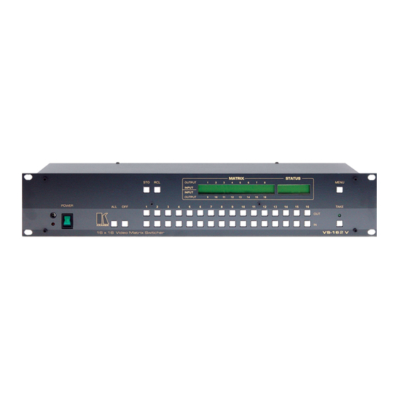
Your Video Matrix Switcher Figure 1: VS-162V 16x16 Video Matrix Switcher... -
Page 10: Table 1: Front Panel Vs-162V 16X16 Video Matrix Switcher Features
Your Video Matrix Switcher Table 1: Front Panel VS-162V 16x16 Video Matrix Switcher Features Feature Function IR Receiver The red LED is illuminated when receiving signals from the Infrared remote control transmitter ALL Button Pressing ALL followed by an INPUT button, connects that input to... -
Page 11: Using The Ir Transmitter
This distance can be extended to up to 60 meters when used with three extension cables Before using the external IR receiver, be sure to arrange for your Kramer dealer to insert the internal IR connection cable with the 3.5mm connector 1 1 F that fits into the REMOTE IR opening on the rear panel. -
Page 12: Installing The Vs-162V In A Rack
Pay particular attention to situations where • If you are using a Kramer rack electricity is supplied indirectly (when the power cord adapter kit (for a machine that is not is not plugged directly into the socket in the wall), for 19"), see the Rack Adapters user... -
Page 13: Installing And Operating A Single Vs-162V - Overview
Unlock front panel TAKE; TAKE Change default setup Press the Menu button several times until you reach the appropriate Menu setup command and follow the instructions 1 Switch OFF the power on each device before connecting it to your VS-162V... -
Page 14: Configuring The Vs-162V Video Matrix Switcher
Configuring the VS-162V Video Matrix Switcher Configuring the VS-162V Video Matrix Switcher Using the VS-162V unit and/or other 16x16 matrix switchers in the series you can assemble the following kinds of systems: • A standalone switcher (see section 7.1) •... -
Page 15: Configuring An 8X8 S-Video (Y/C) Switcher
Figure 3: Configuring the VS-162V for Composite Video (CV) 7.1.2 Configuring an 8x8 s-Video (Y/C) Switcher To configure a single VS-162V switcher as an 8x8 video matrix switcher (with 8 inputs and 8 outputs) for s-Video (Y/C), group the inputs and... -
Page 16: Configuring A 5X5 Yuv/Rgb Switcher
Configuring the VS-162V Video Matrix Switcher 7.1.3 Configuring a 5x5 YUV/RGB Switcher To configure a single VS-162V switcher as a 5x5 video matrix switcher for YUV (or RGB), group the inputs and outputs into sets of 3, as shown in Figure 5 . -
Page 17: Configuring 16X16 Multi-Channel Video Switchers
For example, for composite configuration, a single VS-162V unit provides 16 inputs and 16 outputs. However, for s-Video (Y/C) configuration you need two VS-162V units to provide 16 inputs and 16 outputs. In a multi-channel video switcher configuration, one unit must be the master (with DIP 6 OFF) while the other units are slaves (with DIP 6 ON). -
Page 18: Configuring A 3-Unit 16X16 Yuv/Rgb Switcher
VS-162V switchers, as shown in Figure 7 Figure 7: Configuring a 16x16 YUV (RGB) Switcher with 3 VS-162V Units 1 For a description of how to connect the RS-485 connectors between the VS-162V switchers, refer to section KRAMER: SIMPLE CREATIVE TECHNOLOGY... -
Page 19: Configuring A 4-Unit 16X16 Rgbs Switcher
Configuring the VS-162V Video Matrix Switcher 7.2.3 Configuring a 4-Unit 16x16 RGBS Switcher To configure four VS-162V switchers as a 16x16 RGBS video matrix switcher, combine three VS-162V switchers for YUV (RGB) as shown in Figure Configuring a Multi-Unit Matrix Switcher... -
Page 20: Configuring A 32X16 Switcher
Figure 1. Set the MACHINE # on both VS-162V units to #1 (see section 8.2). 2. Set the MACHINE ADDRESS # on one VS-162V unit to 1 and on the other VS-162V unit to 7 (refer to Figure 3. -
Page 21: Configuring A 32X32 Switcher
(refer to Figure 3. Set DIP 6 OFF on each of the four VS-162V units. 4. Using T-connectors, connect INPUTS 1 to 16 on the VS-162V unit designated as MACHINE ADDRESS # 2 with INPUTS 1 to 16 on the VS- 162V unit designated as MACHINE ADDRESS # 1. -
Page 22: Configuring A System Of Interconnected Switchers
Figure 10: Connecting the 32x32 Switcher Configuring a System of Interconnected Switchers A major advantage of the VS-162V is that it belongs to the series of 16x16 matrix switchers that can interconnect with other switchers in the series. This series includes, but is not limited to, VS-1616A (a 16x16 analog... -
Page 23: Figure 11: Assembling A System Of Interconnected Switchers
Configuring the VS-162V Video Matrix Switcher Figure 11: Assembling a System of Interconnected Switchers Refer to section for how to set the DIP-switches, and to section how to control this group of interconnected varied-format 16x16 series switchers, and other configurations. -
Page 24: Understanding Addressing And System Modes
Understanding Addressing and System Modes Understanding Addressing and System Modes In order to control multiple machines, the VS-162V uses a system of addressing that includes hardware DIP-switches and menu commands. The DIP-switches are used to set the MACHINE# and menu commands are used to set the MACHINE ADDRESS #. -
Page 25: Setting The Machine
A valid MACHINE ADDRESS # is from 1 to 36. Understanding the SYSTEM Mode DIP-switch 5 defines whether the VS-162V unit communicates with other switchers via a common control line. You can set DIP 5 OFF to disable the Follow-SYSTEM mode in the following applications: •... -
Page 26: Understanding The Slave Mode
In the example shown in Figure 7, the first VS-162V unit is the master (with DIP 6 set OFF disabling the slave mode) and the second and third VS-162V units are slaves (with DIP 6 set ON enabling the slave mode). -
Page 27: Connecting The Rs-232 Control Interface
The RS-232 daisy chain switcher arrangement is transparent. This lets you arrange the switchers (from the series of 16x16 matrix switchers) according to your requirements, and not according to a fixed sequence dependent on the MACHINE # and/or MACHINE ADDRESS #. Figure 13: Connecting a PC to 4 VS-162V Units... -
Page 28: Connecting Two Units With A Null-Modem Adapter
2. On the second VS-162V unit, set DIP 7 ON (disabling null-modem adapter 9.1.3 Connecting to a 9-pin PC COM Port with a Null-Modem Adapter To connect the 9-pin D-sub COM port of a PC to a VS-162V unit, using a null-modem adapter: 1. -
Page 29: Connecting To A 9-Pin Pc Com Port Without A Null-Modem Adapter
) on the VS-162V unit. 9.1.5 Connecting to a 25-pin PC COM Port with a Null-Modem Adapter To connect the 25-pin D-sub COM port of a PC to a VS-162V unit, using a null-modem adapter: 1. Connect a flat cable... -
Page 30: Connecting The Rs-485 Control Interface
1. Connect the “+” PIN on the first VS-162V unit to the “+” PIN on the second VS-162V unit or other unit 2. Connect the “-” PIN on the first VS-162V unit to the “-” PIN on the second VS-162V unit or other unit 3. -
Page 31: Figure 16: Connecting The Rs-485 Connectors Between Two Vs-162V Units
Connecting a Control Interface Figure 16: Connecting the RS-485 Connectors between Two VS-162V Units Figure 17 illustrates the RS-485 line that connects: • Between each VS-162V unit • To the PC via a Kramer Tools VP-43xl Interface Converter (connect the 9-pin D-sub PC COM port to the “RS-232 in” 9-pin D-sub port on the VP-43xl. -
Page 32: Figure 17: An Rs-485 Control Interface Setup
Connecting a Control Interface Figure 17: An RS-485 Control Interface Setup KRAMER: SIMPLE CREATIVE TECHNOLOGY... -
Page 33: Configuring The Sync
Connecting a Control Interface Configuring the Sync On the VS-162V, you can select one of the following, as the sync input: • EXTERNAL (“sync in” BNC connector) • INPUT # 1 BNC connector • MTX (Sync from Matrix) RS-485 terminal block connector, when... -
Page 34: Operating Your Video Matrix Switcher
After switching on the power, the MATRIX and STATUS displays show the following screens in sequence: 1 For instructions on using Kramer Windows 95/98/NT Control Software, refer to the separate user manual (included on the CD-ROM in .pdf format), Kramer Control Software 2 Version 1.5 is shown in the Status Display as an example;... -
Page 35: Using The Front Panel Buttons
Operating Your Video Matrix Switcher Figure 19: Default Startup Status Display Sequence 10.2 Using the Front Panel Buttons You can switch (see section 10.4) and clear (see section 10.5): • One input to one output • Several inputs to several outputs •... -
Page 36: Toggling Between The At Once And Confirm Modes
One input to all outputs (see section 10.4.3) 10.4.1 Switching One Input to One Output Pressing an OUT-IN combination when your VS-162V operates in the AT ONCE mode implements the switch immediately. To switch one input to one output (AT ONCE mode): 1. -
Page 37: Switching Several Inputs To Several Outputs
# y Where x is the output number and y is the input number Pressing an OUT-IN combination when your VS-162V operates in the CONFIRM mode (and the TAKE LED is lit), requires user confirmation. To switch one input to one output (CONFIRM mode): 1. -
Page 38: Switching One Input To All Outputs
The MATRIX display shows the identical two non-flashing digits (representing that input number) for all outputs. 1 Continuously, within the limit of the timeout (approximately 30 seconds to one minute) 2 That corresponds with the second OUT button KRAMER: SIMPLE CREATIVE TECHNOLOGY... -
Page 39: Clearing
Operating Your Video Matrix Switcher 10.5 Clearing You can clear (delete): • One output (see section 10.5.1) • Several outputs (see section 10.5.2) • All outputs (see section 10.5.3) 10.5.1 Clearing an Output To clear an output (in the AT ONCE mode): 1. -
Page 40: Clearing Several Outputs
The MATRIX display shows the sets of two flashing digits, representing the present input number for each specific output. 1 For example, pressing OUT button 9 shows the flashing digits 01 if input 1 was previously routed to OUT 9 KRAMER: SIMPLE CREATIVE TECHNOLOGY... -
Page 41: Clearing All Outputs
Operating Your Video Matrix Switcher 6. After completing the sequence, press the TAKE button to confirm the actions. The inputs are cleared and the TAKE LED lights. The MATRIX display does not show any Input # in its place. 10.5.3 Clearing All Outputs To clear all outputs (in the AT ONCE mode): 1. -
Page 42: Recalling Setups
TAKE LED flashes. The STATUS Display shows the message: 1 However, pressing # 3 followed by the TAKE button will also enter the # 3 2 However, pressing # 3 followed by the TAKE button will also enter the # 3 KRAMER: SIMPLE CREATIVE TECHNOLOGY... -
Page 43: Menu Commands
MENU Commands SETUP # xy Load ? Where xy are the OUT buttons. 3. Preview the setup to decide whether to implement it. If not, you can scan the other setups, by pressing different OUT buttons. To stop previewing the setups, press a non-relevant button, such as an IN button. -
Page 44: Figure 20: Sequence Of Menu Commands
MACHINE yes -> TAKE, next -> MENU initial RESET yes -> TAKE, next -> MENU Figure 20: Sequence of MENU Commands You can stop changing a setup at any time by pressing any IN button. KRAMER: SIMPLE CREATIVE TECHNOLOGY... -
Page 45: Locking And Unlocking The Front Panel
MENU Commands 11.1 Locking and Unlocking the Front Panel To prevent changing the settings accidentally or tampering with the unit via the front panel buttons, lock your VS-162V. Unlocking releases the protection mechanism. • To lock the VS-162V: 1. Press the MENU button once. -
Page 46: Choosing The Follow Or Breakaway From System Mode
4 Also applies to a VS-1616A unit or a VS-1616AD unit 5 The VS-162V unit changes its status immediately and goes to the Follow-system mode 6 Or VS-1616A or VS-1616AD unit (as well as other 16x16 matrix switchers in the same series) -
Page 47: Choosing The Video Format Setting
UNIT is set in mode FOLLOW system If the status of the VS-162V unit differs from that of the other unit(s), set the VS-162V unit to the Follow-SYSTEM mode. The MATRIX display flashes the new status of the switcher and the TAKE LED flashes. Pressing... -
Page 48: Setting The Machine Address
1 If currently configured for composite (CV) 2 Depending on the required video format 3 Pressing OUT button # 1 when the machine is already configured for composite (CV) will show the message: requested the same format NO CHANGES made KRAMER: SIMPLE CREATIVE TECHNOLOGY... -
Page 49: Changing The Standalone Machine Address To A Large Matrix
MENU Commands Plan your system according to the chart in Figure 8 before setting the MACHINE ADDRESS, because in a matrix configuration you need to enter the highest MACHINE ADDRESS as well as the MACHINE ADDRESS. 11.4.1 Changing the Standalone MACHINE ADDRESS to a Large Matrix To set the MACHINE ADDRESS: 1. -
Page 50: Changing The Large Matrix Machine Address To Standalone
-> TAKE, next -> MENU 2. Press the TAKE button. The displays show the messages: OUTkey 1: Stand-Alone UNIT Current Matrix 2: Large Matrix 1 Indicating that the machine is not set to standalone KRAMER: SIMPLE CREATIVE TECHNOLOGY... -
Page 51: Changing To A Different Large Matrix Machine Address
MENU Commands 3. Press the OUT button # 1. The displays show the messages: STAND ALONE UNIT (Mach# 01)? Current Press TAKE to confirm Matrix 4. Press the TAKE button again. The MATRIX display shows the message: MACHINE ADDRESS changed now STAND-ALONE 11.4.3 Changing to a Different Large Matrix MACHINE ADDRESS To set the MACHINE ADDRESS:... -
Page 52: Choosing The Switching Method Setting
11.5.2 describes how to configure a SWITCHING METHOD. 11.5.1 Understanding the SWITCHING METHOD Settings Setting the VS-162V unit as a Stand-Alone UNIT provides a choice of three SWITCHING METHOD settings: • NoVIS - switching occurs immediately after completion of front panel or dry-contact operation or immediately after receiving an RS-232 or RS-485 command, or an IR command. -
Page 53: Figure 21: Choosing The Mtx (Sync From Matrix) Setting
INT# 1 (internal sync) - switching occurs during the vertical interval of the video reference signal connected to IN # 1 Setting the VS-162V unit as a Large Matrix (instead of as a Stand-Alone UNIT) provides a choice of 4 SWITCHING METHOD settings: •... -
Page 54: Configuring A Switching Method
The displays show the messages: Outkey 1: External keys OFF current: 2: External keys ON X-key ON 1 Indicating that the machine is currently set to the external switching method setting 2 Indicating that the external keys are currently activated KRAMER: SIMPLE CREATIVE TECHNOLOGY... -
Page 55: Setting The Store/Recall Keyboard Mode
MENU Commands 3. Press the OUT button 1 to deactivate the External keys. The TAKE LED flashes and the displays show the messages: Turn OFF external keys? current: Press TAKE to execute X-key ON 4. Press the TAKE button. The displays show the messages: External Keyboard mode current: changed... -
Page 56: Choosing The Communication Setting
To choose the No Reply response option, for example, do the following: 1. Press the MENU button until you reach the COMMUNICATION setting. The MATRIX display shows the message: COMMUNICATION setting yes -> TAKE, next -> MENU KRAMER: SIMPLE CREATIVE TECHNOLOGY... -
Page 57: Setting The Ir Remote Control
2: InfraredREMOTE ON remote OFF 1 After enabling the IR REMOTE control command, remotely control the VS-162V via the RC-IR2 remote control transmitter pointed at the remote receiver on the VS-162V’s front panel (item 1 in Figure 2 You can download it from the Internet at this URL http://www.kramerelectronics.com/manuals.html... -
Page 58: Choosing The Auto Store Current Setup
Press TAKE to execute NO save 4. Press the TAKE button again. The displays show the messages: AUTOSAVE mode Current: changed AutoSave 1 For example, press # 6 followed by # 2 to switch input 2 to output 6 KRAMER: SIMPLE CREATIVE TECHNOLOGY... -
Page 59: Identifying The Machine
1 Without having to switch the power off and on 2 Sometimes called a “soft reset” 3 Each VS-162V unit ships in its factory default state that is a 16x16 composite video matrix, with all setups empty and each input connected to its corresponding output (for example, 1-to-1) -
Page 60: Upgrading The Flash Memory
12.1 Connecting the PC to the RS-232 Port Before installing the latest Kramer firmware version on a VS-162V unit, connect: • The COM port on your PC to the RS-232 IN port on the VS-162V unit When simultaneously upgrading the firmware on several VS-162V units: •... -
Page 61: Upgrading The Firmware
At this stage, and at any time previously, you can cancel the operation by pressing any button, other than the TAKE button. 1 Refer to section for full details 2 Upgrading firmware resets your VS-162V unit to the factory default. This includes erasing all setups... - Page 62 Start transmission from PC Note: If upgrading the firmware on more than one VS-162V unit, be sure to perform the above steps, 5 to 9, on each VS-162V unit before continuing. 11. From the K-Sender program of your PC, click the Send button.
-
Page 63: Technical Specifications
Technical Specifications Table 9 includes the technical specifications: Table 9: Technical Specifications of the VS-162V Video Matrix Switcher 16 composite video, or 8 s-Video, or 4 RGBS, or 5 YUV, 1 Vpp / 75Ω on BNC INPUTS: connectors 16 composite video, or 8 s-Video, or 4 RGBS, or 5 YUV, 1 Vpp / 75Ω... -
Page 64: Table 10: Hex Table For The Vs-162V Video Matrix Switcher
Communication Protocol Table 10: Hex Table for the VS-162V Video Matrix Switcher KRAMER: SIMPLE CREATIVE TECHNOLOGY... - Page 65 EXCLUSION OF DAMAGES The liability of Kramer for any effective products is limited to the repair or replacement of the product at our option. Kramer shall not be liable for: 1. Damage to other property caused by defects in this product, damages based upon inconvenience, loss of use of the product, loss of time, commercial loss;...
- Page 66 For the latest information on our products and a list of Kramer distributors, visit our Web site: www.kramerelectronics.com where updates to this user manual may be found. We welcome your questions, comments and feedback. Safety Warning: Disconnect the unit from the power supply before opening/servicing.
Need help?
Do you have a question about the VS-162V and is the answer not in the manual?
Questions and answers