Table of Contents
Advertisement
Quick Links
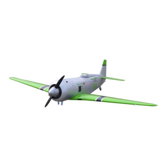
Code : SEA 302
ASSEMBLY MANUAL
Speciications:
Wingspan--------------- 70.9 in (180.0 cm)
Wing area--------------- 850.3 sq.ins (54.9 sq.dm)
Weight------------------- 13.2 lbs (6.0 kg)
Length------------------- 54.6 in (138.8 cm)
Engine/Motor size----- 30-35cc gasoline
Radio--------------------- 7 channels with 7 servos
1
Advertisement
Table of Contents

Subscribe to Our Youtube Channel
Related Manuals for Seagull Models YAK 11


Summary of Contents for Seagull Models YAK 11
- Page 1 Code : SEA 302 ASSEMBLY MANUAL Speciications: Wingspan--------------- 70.9 in (180.0 cm) Wing area--------------- 850.3 sq.ins (54.9 sq.dm) Weight------------------- 13.2 lbs (6.0 kg) Length------------------- 54.6 in (138.8 cm) Engine/Motor size----- 30-35cc gasoline Radio--------------------- 7 channels with 7 servos...
-
Page 2: Kit Contents
Instruction Manual. RENO AIR CARE YAK-11 “PERESTROIKA” INTRODUCTION hank you for choosing the RENO AIR CARE YAK-11 “PERESTROIKA” ARTF by SG MODELS . he RENO AIR CARE YAK-11 “PERESTROIKA” was designed with the inter- mediate/advanced sport lyer in mind. It is a semi scale airplane which is easy to ly and quick to assemble. -
Page 3: Additional Items Required
KIT CONTENTS HINGING THE FLAP SEA302 RENO AIR CARE YAK-11 “PERESTROIKA” 1. Fuselage 2. Wing set (2) 3. Tail set (2) 4. Canopy 5. Cowling 6. Wing tube 7. Pilot 8. landing gear 9. Fuel tank 10. Tail wheel 2x10mm 11. -
Page 4: Hinging The Aileron
Instruction Manual. RENO AIR CARE YAK-11 “PERESTROIKA” Slide the wing panel on the aileron until there is only a slight gap. he hinge is now centered on the wing panel and aileron. Remove the T-pins and snug the aileron against the wing panel. A gap of 1/64” or less should be maintained between the wing panel and aileron. - Page 5 Turn the wing panel over and delect the aileron in the opposite direction from the opposite side. Apply thin C/A glue to each hinge, making sure that the C/A penetrates into both the aileron and wing panel. Using C/A remover/debonder and a paper towel, remove any excess C/A glue that may have accumulated on the wing or in the Ailerons control horn...
- Page 6 Instruction Manual. RENO AIR CARE YAK-11 “PERESTROIKA” Before the epoxy fully cures, remove the tape from around the control horn. his will allow the epoxy to low around the control horn, creating a small ilet between the control horn and surface for a iished look and secure bond.
-
Page 7: Installing The Aileron Servos
Minimum servo spec. Torque : 80 oz-in (5.8 kg-cm) @ 4.8V; 100 oz-in (7.2 kg-cm) @ 6.0V Because the size of servos difer, you may need to adjust the size of the precut opening in the mount. he notch in the sides of the mount allow the servo lead to pass through. - Page 8 Instruction Manual. RENO AIR CARE YAK-11 “PERESTROIKA” Remove the string from the wing at the servo location and use the tape to attach it to the servo extension lead. Pull the lead through the wing and remove the string. C/A glue Use dental loss or heatshrink tube to secure the connection so they cannot be- come unplugged.
-
Page 9: Aileron Pushrod Installation
Set the aileron hatch in place and use a Phillips screw driver to install it with four wood screws. 2x10mm 75mm M3 lock nut M3 clevis INSTALLING THE FLAP SERVO Repeat the procedure for the lap servo. INSTALLING THE FLAP PUSHROD Repeat the procedure for the aileron pushrod. -
Page 10: Wing Assembly
Instruction Manual. RENO AIR CARE YAK-11 “PERESTROIKA” M3 lock nut M3 clevis INSTALLING RETRACTABLE LANDING GEAR Locate items necessary to install Sprin Landing Gear. WING ASSEMBLY You use this fork set JP ER-120-90degree. - Page 11 head locker glue 3x20mm...
- Page 12 Instruction Manual. RENO AIR CARE YAK-11 “PERESTROIKA” 3x10mm...
-
Page 13: Installing The Fuselage Servos
INSTALLING THE FUSELAGE SERVOS Because the size of servos difer, you may need to adjust the size of the precut opening in the mount. he notch in the sides of the mount allow the servo lead to pass through. Install the rubber grommets and brass collets into all servos. -
Page 14: Installing The Stopper Assembly
Instruction Manual. RENO AIR CARE YAK-11 “PERESTROIKA” INSTALLING THE ENGINE SWITCH hrottle servo arm Rudder servo arm Elevator servo arm Trim and cut INSTALLING THE RECEIVER SWITCH Install the switch into the precut hole in the side, in the fuselage. 3/32”... -
Page 15: Fuel Tank Installation
When satisied with the alignment of the stopper assembly tighten the 3x20mm ma- chine screw until the rubber stopper expands and seals the tank opening. Do not overtight- en the assembly as this could cause the tank to split. FUEL TANK INSTALLATION Vent tube Fuel pick up tube Fuel ill tube... -
Page 16: Mounting The Engine
Instruction Manual. RENO AIR CARE YAK-11 “PERESTROIKA” Connect the lines from the tank to the You should mark which tube is the vent and which is the fuel pickup when you attach engine and muler. he vent line will fuel tubing to the tubes in the stopper. Once connectto the muler and the line from the tank is installed inside the fuselage, it may the clunk tothe carburetor. - Page 17 M5x100mm 5.1mm 160mm Position the engine with the drive washer (160mm) forward of the irewall.
- Page 18 Instruction Manual. RENO AIR CARE YAK-11 “PERESTROIKA” Use medium CA to glue the pushrod standof to the inside of the fuselage and the pushrod tube. Ignition Module Reinstall the servo horn by sliding the connector over the pushrod wire. Cent- er the throttle stick and trim and install the servo horn perpendiular to the servo center line.
- Page 19 COWLING Please see below pictures. Tape the cowl to the fuselage using low- tack tape.
- Page 20 Instruction Manual. RENO AIR CARE YAK-11 “PERESTROIKA” Install the muler and muler extension onto the engine and make the cutout in the cowl for muler clearance. Connect the fuel and pressure lines to the carbu- retor, muler and fuel iler valve. Secure the cowl to fuselage using the M3x10mm socket head screws.
- Page 21 - Motor: 160 - 2700 Watts - Propeller: 18x8 ~ 20x10 - ESC: 70A - 100A - 9S - 10S Lipo Attach the electric motor box to the ire- wall centered with the cross lines drawn on the electric motor box and irewall. Using M4x25mm to secure the motor box to the irewall.
- Page 22 Instruction Manual. RENO AIR CARE YAK-11 “PERESTROIKA” Attach the motor mount to the front of the electric motor box using four 4mm blind nut, four M4x20mm hex head bolts to se- cure the motor. Please see picture shown. Blind nut Attach the motor to the front of the elec- tric motor box using four 4mm blind nut, four M4x20mm hex head bolts to secure...
-
Page 23: Installing The Spinner
Balsa stick Epoxy Battery Attach the speed control to the side INSTALLING THE SPINNER of the motor box using two-sided tape and tie wraps. Connect the appropriate leads from the speed control to the mo- Install the spinner backplate, propeller tor. -
Page 24: Hinging The Elevator
Instruction Manual. RENO AIR CARE YAK-11 “PERESTROIKA” HINGING THE ELEVATOR ElevatorFiberglass control horn Glue the elevator hinges in place using the same techniques used to hinge the ai- lerons. Epoxy. INSTALLING THE HORIZONTAL STABILIZER Using a ruler and a pen, locate the cen- INSTALL ELEVATOR CONTROL HORN terline of the horizontal stabilizer, at the trailing edge, and place a mark. - Page 25 Slide the stabilizer into place in the When cutting through the covering to precut slot in the rear of the fuselage. he remove it, cut with only enough pressure to stabilizer should be pushed irmly against only cut through the covering itself. Cutting the front of the slot.
-
Page 26: Hinging The Rudder
Instruction Manual. RENO AIR CARE YAK-11 “PERESTROIKA” Epoxy HINGING THE RUDDER Glue the top two rudder hinges in place using the same techniques used to hinge the ailerons. he lower hinge will be glued when the Rudder Fiberglass control horn i/rudder assembly is attached to the fu- selage. - Page 27 While holding the vertical stabilizer im- ly in place, use a pen and draw a line on eachside of the vertical stabilizer where it meets the top of the fuselage. Epoxy Vertical Stabilizer. Horizontal 90º Stabilizer. Slide the vertical stabilizer into the slot in the top of the fuselage.
- Page 28 Instruction Manual. RENO AIR CARE YAK-11 “PERESTROIKA” When you are sure that everything is hread one clevis and M2 lock nut on aligned correctly, mix up a generous to each elevator control rod. hread the amount of Flash 30 Minute Epoxy. Ap- horns on until they are lush with the ply a thin layer to the mounting slot ends of the control rods.
-
Page 29: Mounting The Tail Wheel
Nylon snap keeper MOUNTING THE TAIL WHEEL Locate items necessary to install tail wheel. RUDDER PUSHROD INSTALLATION Repeat steps as same as steps done for elevator. M2 clevis M2 lock nut... - Page 30 Instruction Manual. RENO AIR CARE YAK-11 “PERESTROIKA”...
- Page 31 INSTALLATION PILOT AND CANOPY Locate items necessary to install pilot and canopy. A scale pilot is included with this ARF. he Pilot included itting well to the cock- pit. (or you can order others scale pilot igures made by SG Models. hey are available at SG Models distributors.) If you are going to install a pilot igure, please use a sanding bar to sand the base...
- Page 32 Instruction Manual. RENO AIR CARE YAK-11 “PERESTROIKA” Wrap the receiver and battery pack in the protective foam rubber to protect them from vibration. Route the antenna in the antenna tube inside the fuselage and secure it to the bottom of fuselage using a plastic tape. 110mm Epoxy Battery...
- Page 33 Wing bolt Epoxy hen, install wing guns on the wings.
-
Page 34: Apply The Decals
Instruction Manual. RENO AIR CARE YAK-11 “PERESTROIKA” BALANCING 1) It is critical that your airplane be balanced correctly. Improper balance will cause your plane to lose control and crash. THE CENTER OF GRAV- ITY IS LOCATED 170-180MM BACK FROM THE LEADING EDGE OF THE WING AT THE WING ROOT. -
Page 35: Control Throws
Lit the model. If the tail drops when CONTROL THROWS you lit, the model is “tail heavy” and you must add weight* to the nose. If the nose Ailerons: Rudder: drops, it is “nose heavy” and you must High Rate : High Rate : add weight* to the tail to balance. -
Page 36: Flight Preparation
Instruction Manual. RENO AIR CARE YAK-11 “PERESTROIKA” FLIGHT PREPARATION PREFLIGHT CHECK Check the operation and direction of the 1) Completely charge your transmit- elevator, rudder, ailerons and throttle. ter and receiver batteries before your irst day of lying. A) Plug in your radio system per the 2) Check every bolt and every glue manufacturer’s instructions and turn eve- joint in the RENO AIR CARE YAK-11... - Page 37 If you have any queries, or are interested in our products, please feel free to contact us Factory : 12/101A - Hamlet 4 - Le Van Khuong Street - Dong hanh Ward - Hoc Mon District - Ho Chi Minh City - Viet Nam. Oice : 62/8 Ngo Tat To Street - Ward 19 - Binh hanh District - Ho Chi Minh City - Viet Nam Phone : 848 - 86622289 or 848- 36018777...
Need help?
Do you have a question about the YAK 11 and is the answer not in the manual?
Questions and answers