Table of Contents
Advertisement
Quick Links
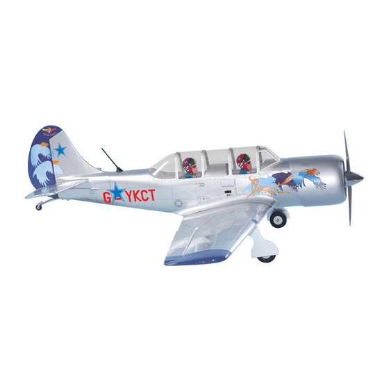
YAK 52
MS:119
ASSEMBLY MANUAL
"Graphics and specifications may change without notice".
Specifications:
Wing span ----------------------------63.4in (161cm).
Wing area -----------------689.8sq.in (44.5sq dm).
Weight ------------------------9.3-10.1lbs (4.2-4.6kg).
Length ------------------------------51.7in (131.3cm).
Engine ------------------ 0.91cu.in ---------2-stroke.
1.20cu.in ---------4-stroke.
Radio -------------------6 channels with 8 servos.
Retracts landing gear (included).
Advertisement
Table of Contents

Related Manuals for Seagull Models YAK 52


Summary of Contents for Seagull Models YAK 52
- Page 1 YAK 52 MS:119 ASSEMBLY MANUAL “Graphics and specifications may change without notice”. Specifications: Wing span ----------------------------63.4in (161cm). Wing area -----------------689.8sq.in (44.5sq dm). Weight ------------------------9.3-10.1lbs (4.2-4.6kg). Length ------------------------------51.7in (131.3cm). Engine ------------------ 0.91cu.in ---------2-stroke. 1.20cu.in ---------4-stroke. Radio -------------------6 channels with 8 servos.
-
Page 2: Kit Contents
YAK 52 INTRODUCTION. Thank you for choosing the YAK 52 ARTF by SEAGULL MODELS. The YAK 52 was designed with the intermediate/advanced sport flyer in mind. It is a semi scale airplane which is easy to fly and quick to assemble. The airframe is conventionally built using balsa, plywood to make it stronger than the average ARTF , yet the design allows the aeroplane to be kept light. -
Page 3: Hinging The Ailerons
www.seagullmodels.com CONTEN.TS HINGING THE AILERONS . Note: The control surfaces, including the Fuselage ailerons, elevators, and rudder, are Left wing panel prehinged with hinges installed, but Right wing panel Tail set (2) the hinges are not glued in place. It Canopy is imperative that you properly Aluminum wing tube... -
Page 4: Hinging The Elevator
Instruction Manual. YAK 52 Hinge. 5) Turn the wing panel over and deflect the 4) Deflect the aileron and completely aileron in the opposite direction from the saturate each hinge with thin C/A glue. The opposite side. Apply thin C/A glue to each... -
Page 5: Hinging The Rudder
www.seagullmodels.com HINGING THE RUDDER. Glue the rudder hinges in place using the same techniques used to hinge the ailerons. 1) Attach the plastic wing tip to the wing. Use a hobby knife to remove the covering at the wing end. Remove covering. - Page 6 Instruction Manual. YAK 52 3) Once the epoxy cures and use a covering iron to seal the covering on the wing and over the wing tip. Masking tape. 3mm. Place epoxy into hole. This will harden the threads and prevent the crews from pulling loose.
- Page 7 www.seagullmodels.com INSTALL FLAP CONTROL HORN. T-pin. Install the flap control horn using the same method as same as the aileron control horns. C/A glue. 2 sets. 3x30mm. T-pin. C/A glue. C/A glue. Hinge. CONTROL HORN M3 SCREW. Aluminum Washer. Epoxy. Flap control horn.
- Page 8 Instruction Manual. YAK 52 INSTALL RUDDER CONTROL HORN. Repeat steps to install the rudder control horn as same as steps done for ailerons. 3mm. 1 sets. 3x50mm. CONTROL HORN M3 SCREW. Aluminum Washer. Epoxy. Horizontal Elevator Stabilizer 3mm. Aluminum Washer.
-
Page 9: Engine Mount Installation
www.seagullmodels.com Thread locker glue. Rudder control horn. ENGINE MOUNT INSTALLATION. 1) Locate the items necessary to install the engine mount included with your model. . 4x30mm. 2) Use four 4x30mm head bolts and four 4mm washers to attach the engine mount rails to the firewall. -
Page 10: Fuel Tank Installation
Instruction Manual. YAK 52 You should mark which tube is the vent and which is the fuel pickup when you attach fuel tubing to the tubes in the stopper. Once the tank is installed inside the fuselage, it may be difficult to determine which is which. -
Page 11: Installing The Fuselage Servos
www.seagullmodels.com 9) Connect the lines from the tank to the engine and muffler. The vent line will connect to the muffler and the line from the clunk to the Rudder servo. carburetor. Throttle servo. Elevator servo. M3 x 10mm. THROTTLE SERVO ARM INSTALLATION. Install adjustable servo connector in the servo arm as same as picture below: Blow through one of the lines to en-... -
Page 12: Mounting The Engine
Instruction Manual. YAK 52 Trim and cut. 4.5mm. 4) On the fire wall has the location for the throttle pusshrod tube (pre-drill). Switch. MOUNTING THE ENGINE. 1) Position the engine with the drive washer (150mm) forward of the firewall as shown. -
Page 13: Installing The Battery
www.seagullmodels.com Epoxy. 8) Reinstall the servo horn by sliding the connector over the pushrod wire. Center the throttle stick and trim and install the servo horn perpendicular to the servo center line. Battery. Tie wrap. COWLING. 9) Move the throttle stick to the closed position and move the carburetor to closed. - Page 14 Instruction Manual. YAK 52 2) While keeping the back edge of the 2) Attach the electric motor box to the firewall suitable with the cross lines drawn on the electric cowl flush with the marks, align the front of motor box and firewall. Using epoxy and balsa the cowl with the crankshaft of the engine.
- Page 15 www.seagullmodels.com Epoxy. 150mm. 5.2mm. Balsa stick. Blind nut. 3) Attach the motor to the front of the electric motor box using four 4mm blind nut, four M4x15mm hex head bolts to secure the motor. Please see picture shown. Electric motor. M4 x 15mm.
-
Page 16: Installing The Aileron - Flap Servos
Instruction Manual. YAK 52 Battery. M3 x 15mm. 5) Attach the speed control to the side of the motor box using two-sided tape and tie wraps. Connect the appropriate leads from the speed control to the motor. Make sure the leads will not interfere with the operation of the motor. - Page 17 www.seagullmodels.com 3) Use drill bit in a pin vise to drill the mouting holes in the blocks. 8) A string has been provided in the wing to pull the aileron lead through to the wing root. Remove the string from the wing at the servo 4) Apply 2-3 drops of thin C/A to each of the location and use the tape to attach it to the mounting holes.
- Page 18 Instruction Manual. YAK 52 AILERON PUSHROD HORN INSTALLATION Mark. Pen. 1) Mark the control wire where it crosses the servo arm hole. Bend at the mark. 8mm. Cut. 9) Set the aileron hatch in place and use a Phillips screw driver to install it with four wood 2) Make a 90-degree bend at the mark and cut screws.
- Page 19 www.seagullmodels.com 3) Connect the linkage as shown and secure Metal clevis. M2 lock nut. the control wire with a snap keeper. Aileron. Snap keeper. M2 lock nut. Servo arm. Wing. Snap keeper. Repeat the procedure for the other aileron servo. INSTALLING THE FLAP SERVO.
-
Page 20: Wing Assembly
Instruction Manual. YAK 52 3) Install the led light to the black plastic mount to hold the LED in place with C/A glue as shown. C/A glue. C/A glue. 5) Use transparent plastic to cover the LED light with C/A glue as shown. - Page 21 www.seagullmodels.com SERVO GEAR INSTALLATION. Metal connector. 25mm. Epoxy. Servo arm. Servo for retractable only. Adjustable servo Servo arm. connector. Loctile Epoxy. secure. 25mm. Wing bottom. Epoxy. Electric wire. INSTALLING RETRACTABLE LANDING GEAR. Epoxy. Masking tape. 1) Locate the items necessary to install the retracts landing gear and retract linkage instal- lation.
- Page 22 Instruction Manual. YAK 52 Epoxy. Epoxy. 200mm. 220mm. 4) Position the landing gear onto the landing gear rails. Mark the location of the holes for mouting the landing gear. 2) Cut the covering from the bottom of the wing for retracts landing gear installation.
- Page 23 www.seagullmodels.com 5) Install the linkage into the connector on the end of the retract unit as shown. Mounting the landing gear to the rail with four M3x 25mm. M3x25mm. M2 lock nut. M2 clevis. Cut. 6) Install a wheel and two wheel collars on the main landing gear.
- Page 24 Instruction Manual. YAK 52 Wheel Fairing. Open Position. servo arm. Close Position. 12mm. servo arm.
-
Page 25: Installing The Horizontal Stabilizer
www.seagullmodels.com Remove the covering. Cut. 3) Put the stabilizer into place in the position of the fuselage. 4) Install the stabilizer onto the fuselage. Align the centerline drawn on the top and the rear of the stabilizer with the centre of the fu- selage. -
Page 26: Installing The Vertical Stabilizer
Instruction Manual. YAK 52 Epoxy. Pen. Epoxy. 7) Remove the stabilizer. Using the lines you just drew as a guide, carefully remove the covering from between them using a model- ing knife. Remove the covering. Fill epoxy. When cutting through the covering to... - Page 27 www.seagullmodels.com 1) Using a modeling knife, remove the covering from over the precut hinge slot cut into the lower rear portion of the fuselage. Remove covering. Epoxy. 4) When you are sure that everything is aligned correctly, mix up a generous amount of Fill epoxy.
- Page 28 Instruction Manual. YAK 52 ELEVATOR PUSHROD HORN INSTALLATION. 1) Install the elevator control horn using the same method as with the aileron control horns. 2) Position the elevator control horn on the both side of elevator. Elevator control horn. Elevator pushrod.
- Page 29 www.seagullmodels.com 8mm. Pen. 8mm. Cut. RUDDER PUSHROD HORN INSTALLATION. M2 lock nut . M2 clevis. 8mm. Control horn. Elevator pushrod. M2 lock nut. Rudder pushrod. Metal clevis.
- Page 30 Instruction Manual. YAK 52 Elevator control horn. Elevator pushrod. C/A glue. Rudder control horn. Rudder pushrod. Elevator pushrod. C/A glue. 1) Elevator and rudder pushrods assembly follow pictures below. Elevator control horn. Rudder. Throttle. Elevator. Rudder control horn.
-
Page 31: Mounting The Tail Wheel
www.seagullmodels.com 2) Install servos arm to servos. Notice the M3x30mm. position of the servo arms on the servos. See picture below. Rudder. Elevator. Throttle. MOUNTING THE TAIL WHEEL. Locate items necessary to install tail gear. C/A glue. Spring. M3x30mm. M3x25mm. Tail landing gear. - Page 32 Instruction Manual. YAK 52 - Use scissors to trim the wing fillets. If you are going to install a pilot figure, please use a sanding bar to sand the base of the figure so that it is flat. 3) Position the pilot figure on the canopy floor as show.
-
Page 33: Apply The Decals
www.seagullmodels.com APPLY THE DECALS. Remove covering to see hole. 1) If all the decals are precut and ready to stick. Please be certain the model is clean and free from oily fingerprints and dust. Position decal on the model where desired, using the photos on the box and aid in their location. -
Page 34: Control Throws
Instruction Manual. YAK 52 Accurately mark the balance point on the top ATTACHMENT WING-FUSELAGE. of the wing on both sides of the fuselage. The balance point is located 95 mm back from the Use the two wing bolts to attach the wing to leading edge of the wing at the wing root. -
Page 35: Flight Preparation
A) Plug in your radio system per the 2) Check every bolt and every glue joint manufacturer's instructions and turn every- in the YAK 52 to ensure that thing on. everything is tight and well bonded. B) Check the elevator first. Pull back 3) Double check the balance of the air- on the elevator stick.
Need help?
Do you have a question about the YAK 52 and is the answer not in the manual?
Questions and answers