Table of Contents
Advertisement
Quick Links
Code : SEA 302
ASSEMBLY MANUAL
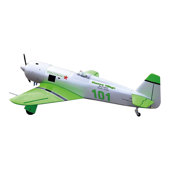
Specifications:
Wingspan--------------- 70.9 in (180.0 cm).
Wing area--------------- 850.3 sq.ins (54.9 sq.dm).
Weight------------------- 11.9 lbs (5.4 kg).
Length------------------- 54.6 in (138.8 cm).
Engine/Motor size----- 20-26cc gasoline.
Radio--------------------- 7 channels with 9 servos.
1
Advertisement
Table of Contents

Related Manuals for Seagull Models RENO AIR CARE YAK-11 PERESTROIKA


Summary of Contents for Seagull Models RENO AIR CARE YAK-11 PERESTROIKA
-
Page 1: Specifications
Code : SEA 302 ASSEMBLY MANUAL Specifications: Wingspan--------------- 70.9 in (180.0 cm). Wing area--------------- 850.3 sq.ins (54.9 sq.dm). Weight------------------- 11.9 lbs (5.4 kg). Length------------------- 54.6 in (138.8 cm). Engine/Motor size----- 20-26cc gasoline. Radio--------------------- 7 channels with 9 servos. -
Page 2: Kit Contents
Instruction Manual. RENO AIR CARE YAK-11 “PERESTROIKA” INTRODUCTION. Thank you for choosing the RENO AIR CARE YAK-11 “PERESTROIKA” ARTF by SG MODELS . The RENO AIR CARE YAK-11 “PERESTROIKA” was designed with the inter- mediate/advanced sport flyer in mind. It is a semi scale airplane which is easy to fly and quick to assemble. -
Page 3: Additional Items Required
HINGING THE FLAP. KIT CONTENTS. SEA302 RENO AIR CARE YAK-11 “PERESTROIKA” 1. Fuselage 2. Wing set (2) 3. Tail set (2) 4. Canopy 5. Cowling 6. Wing tube 7. Pilot 8. landing gear 9. Fuel tank 10. Tail wheel 2x10mm ADDITIONAL ITEMS REQUIRED. -
Page 4: Hinging The Aileron
Instruction Manual. RENO AIR CARE YAK-11 “PERESTROIKA” 3) Slide the wing panel on the aileron un- til there is only a slight gap. The hinge is now centered on the wing panel and ai- leron. Remove the T-pins and snug the aileron against the wing panel. - Page 5 5) Turn the wing panel over and deflect the aileron in the opposite direction from the opposite side. Apply thin C/A glue to each hinge, making sure that the C/A penetrates into both the aileron and wing panel. 6) Using C/A remover/debonder and a paper Epoxy.
- Page 6 Instruction Manual. RENO AIR CARE YAK-11 “PERESTROIKA” 1) Place the servo between the mounting blocks and space it from the hatch. Use a pencil to mark the mounting hole loca- tions on the blocks. Flap control horn INSTALLING THE ALLERON SERVOS 2) Use drill bit in a pin vise to drill the mouting holes in the blocks.
- Page 7 5) Secure the servo to the aileron hatch using Phillips screwdriver and the screws provided with the servo. 6) Apply 1-2 drops of thin C/A to each of the mounting tabs. Allow the C/A to cure without using accelerator. C/A glue 7) Remove the string from the wing at the servo location and use the tape to attach it to the servo extension lead.
- Page 8 Instruction Manual. RENO AIR CARE YAK-11 “PERESTROIKA” INSTALLING THE FLAP SERVO. Repeat the procedure for the flap servo. AILERON PUSHROD INSTALLATION. Please see below pictures. 35mm. INSTALLING THE FLAP PUSHROD. 55mm.
-
Page 9: Wing Assembly
WING ASSEMBLY. Mark. 2.5mm. 3.5x20mm INSTALLING LANDING GEAR. 1)Locate items necessary to install Sprin Landing Gear. - Page 10 Instruction Manual. RENO AIR CARE YAK-11 “PERESTROIKA” 2) Install servo for Retractable landing gear. 3) Slide the wheel on the axle, then se- M3x10mm cure it using the wheel collar. Ask the customer to use this machine. Torque : 222 oz-in (16 kg-cm) @ 4.8V; 278 oz-in (20 kg-cm) @ 6.0V Collar.
- Page 11 M3x10mm Collar. M3x4mm. 4) Secure the landing gear doors to the landing gear struts.
- Page 12 Instruction Manual. RENO AIR CARE YAK-11 “PERESTROIKA” Mark. OPTIONAL RETRACTABLE LANDING GEAR. Electric retractable landing gear is not included in this kit, however it is a very popular add-on as optional. If you want Drill. 2.5mm to use retracts in your RENO AIR CARE YAK-11 “PERESTROIKA”, we recom- mend that you buy a good set of electric retracts as the Himark AM05 Main Gear...
- Page 13 M3x10mm Collar.
- Page 14 Instruction Manual. RENO AIR CARE YAK-11 “PERESTROIKA” Throttle servo arm. Rudder servo arm. INSTALLING THE FUSELAGE SERVOS. Because the size of servos differ, you may need to adjust the size of the precut opening in the mount. The notch in the Elevator servo arm .
- Page 15 2) Using a modeling knife, cut one length of silicon fuel line. Connect one end of the line to the weighted fuel pick up and the other end to the nylon pick up tube. Switch. INSTALLING THE ENGINE SWITCH. Trim and cut. Vent tube.
-
Page 16: Fuel Tank Installation
Instruction Manual. RENO AIR CARE YAK-11 “PERESTROIKA” 5) With the stopper assembly in place, the weighted pick-up should rest away from the rear of the tank and move freely inside the tank. The top of the vent tube should rest just below the top of the tank. -
Page 17: Mounting The Engine
Thead locker glue. MOUNTING THE ENGINE. Blow through one of the lines to ensure the fuel lines have not become kinked inside 1) Position the engine with the drive the fuel tank compartment. Air should flw washer (145mm) forward of the fiewall as through easily. - Page 18 Instruction Manual. RENO AIR CARE YAK-11 “PERESTROIKA” 3) Use a drill to drill the four holes in the engine mount rails. Pushrod wire. Machine screw M4x30mm 4) On the fie wall has the location for the throttle pushrod tube (pre-drill). 5) Slide the pushrod tube in the fiewall and guide it through the fuel tank mount.
- Page 19 8) Reinstall the servo horn by sliding the connector over the pushrod wire. Cent- er the throttle stick and trim and install the servo horn perpendiular to the servo center line. 9) Move the throttle stick to the closed po- sition and move the carburetor to closed.
- Page 20 Instruction Manual. RENO AIR CARE YAK-11 “PERESTROIKA” 2) Use a drill and drill bit to drill the holes for the cowl mounting screws. Make sure the cowl position is correct before drill- ing each hole. 1) Tape the cowl to the fuselage using low-tack tape.
- Page 21 M3x10mm Because of the size of the cowl, it may be nec- essary to use a needle valve extension for the high speed needle valve. Make this out of suf- ficient length 1.5mm wire and install it into the end of the needle valve. Secure the wire in place by tightening the set screw in the side of the needle valve.
- Page 22 Instruction Manual. RENO AIR CARE YAK-11 “PERESTROIKA” - Motor: 110 - 2000 Watts - Propeller: 17x8 ~ 19x10 - ESC: 850A - 8S- 9S Lipo 3) Attach the electric motor box to the firewall suitable with the cross lines drawn on the electric motor box and fire- wall.
-
Page 23: Installing The Spinner
5) Attach the motor to the front of the 6) Attach the speed control to the side electric motor box using four 4mm blind of the motor box using two-sided tape nut, four M4x40mm hex head bolts to se- and tie wraps. Connect the appropriate cure the motor. -
Page 24: Hinging The Elevator
Instruction Manual. RENO AIR CARE YAK-11 “PERESTROIKA” Fiberglass control horn. The propeller should not touch any part of the spinner cone. If it does, use a sharp modeling knife and carefully trim away the spinner cone where the propel- ler comes in contact with it. Epoxy. - Page 25 Pen. 2) Using a modeling knife, carefully re- 5) Remove the stabilizer. Using the lines you just drew as a guide, carefully remove the move the covering at mounting slot of covering from between them using a mod- horizontal stabilizer ( both side of fuse- eling knife.
-
Page 26: Hinging The Rudder
Instruction Manual. RENO AIR CARE YAK-11 “PERESTROIKA” 7) When you are sure that everything is aligned correctly, mix up a generous amount of 30 Minute Epoxy. Apply a thin layer to the top and bottom of the stabilizer mounting area and to the stabilizer mounting platform sides in the fuselage. -
Page 27: Installing Vertical Stabilizer
INSTALLING VERTICAL STABILIZER 3) While holding the vertical stabilizer fimly in place, use a pen and draw a line on eachside of the vertical stabilizer 1) Using a modeling knife, remove the where it meets the top of the fuselage. covering from over the precut hinge slot cut into the lower rear portion of the fu- selage. - Page 28 Instruction Manual. RENO AIR CARE YAK-11 “PERESTROIKA” 5) When you are sure that everything 3) Thread one clevis and M2 lock nut on is aligned correctly, mix up a gener- to each elevator control rod. Thread the ous amount of Flash 30 Minute Epoxy. horns on until they are flush with the Apply a thin layer to the mounting slot ends of the control rods.
-
Page 29: Rudder Pushrod Installation
Nylon snap keeper. MOUNTING THE TAIL WHEEL. RUDDER PUSHROD INSTALLATION. Locate items necessary to install tail wheel. Repeat steps as same as steps done for elevator. M2 clevis M2 lock nut. - Page 30 Instruction Manual. RENO AIR CARE YAK-11 “PERESTROIKA” INSTALLATION PILOT AND CANOPY. 1) Locate items necessary to install pilot and canopy.
- Page 31 110mm Epoxy. 2) A scale pilot is included with this ARF. The Pilot included fitting well to the cock- 4) Epoxy canopy onto the fuselage. Trace pit. (or you can order others scale pilot around the canopy and onto the fuselage figures made by SG Models.
- Page 32 Instruction Manual. RENO AIR CARE YAK-11 “PERESTROIKA” Battery. Wing bolt. Receiver. Battery. ATTACKMENT WING-FUSELAGE.
-
Page 33: Apply The Decals
Epoxy. Epoxy. APPLY THE DECALS. 1) If all the decals are precut and ready to stick. Please be certain the model is clean and free from oily fingerprints and dust. Position decal on the model where de- sired, using the photos on the box and aid in their location. -
Page 34: Control Throws
Instruction Manual. RENO AIR CARE YAK-11 “PERESTROIKA” 3) With the model inverted, place your CONTROL THROWS. fingers on the masking tape and carefully lift the plane. This is the point at which Ailerons: Rudder: your model should balance for your first High Rate : High Rate : flights. - Page 35 15-20mm 15-20mm 20-30mm Fuselage 20-30mm 15-20mm Wing 15-20mm...
-
Page 36: Flight Preparation
Instruction Manual. RENO AIR CARE YAK-11 “PERESTROIKA” FLIGHT PREPARATION. PREFLIGHT CHECK. Check the operation and direction of the 1) Completely charge your transmit- elevator, rudder, ailerons and throttle. ter and receiver batteries before your first day of flying. A) Plug in your radio system per the 2) Check every bolt and every glue manufacturer’s instructions and turn eve- joint in the RENO AIR CARE YAK-11... - Page 37 If you have any queries, or are interested in our products, please feel free to contact us Factory : 12/101A - Hamlet 4 - Le Van Khuong Street - Dong Thanh Ward - Hoc Mon District - Ho Chi Minh City - Viet Nam. Office : 62/8 Ngo Tat To Street - Ward 19 - Binh Thanh District - Ho Chi Minh City - Viet Nam Phone : 848 - 86622289 or 848- 36018777...
Need help?
Do you have a question about the RENO AIR CARE YAK-11 PERESTROIKA and is the answer not in the manual?
Questions and answers