Seagull Models YAK 54 Assembly Manual
Hide thumbs
Also See for YAK 54:
- Assembly manual (24 pages) ,
- Assembly manual (21 pages) ,
- Assembly manual (39 pages)
Table of Contents
Advertisement
Quick Links
Code : SEA 360
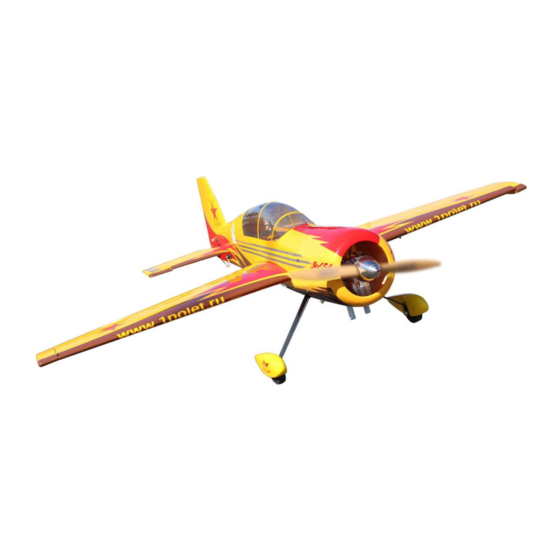
ASSEMBLY MANUAL
Speciications:
Wingspan --------------- 73 in (185.0 cm)
Wing Area -------------- 996.3 sp.in (64.3 dm²)
Weight ------------------ 11.5-12.3 lbs (5.2-5.6 kg)
Length ------------------ 65.7 in (167.0 cm)
Engine ------------------ 35-40cc
Servo-------------------- 5 channels 6 servos
Motor 180/ 3000-3500watt/ ESC 80A-120A/ Lipo
12s 3300-4200mAh
Electric propeller 20x8-21x10
1
Advertisement
Table of Contents

Subscribe to Our Youtube Channel
Related Manuals for Seagull Models YAK 54


Summary of Contents for Seagull Models YAK 54
- Page 1 Code : SEA 360 ASSEMBLY MANUAL Speciications: Wingspan --------------- 73 in (185.0 cm) Wing Area -------------- 996.3 sp.in (64.3 dm²) Weight ------------------ 11.5-12.3 lbs (5.2-5.6 kg) Length ------------------ 65.7 in (167.0 cm) Engine ------------------ 35-40cc Servo-------------------- 5 channels 6 servos Motor 180/ 3000-3500watt/ ESC 80A-120A/ Lipo 12s 3300-4200mAh Electric propeller 20x8-21x10...
-
Page 2: Kit Contents
YAK 54 INTRODUCTION hank you for choosing the YAK 54 ARTF by SG MODELS. he YAK 54 was designed with the intermediate/advanced sport lyer in mind. It is a semi scale airplane which is easy to ly and quick to assemble. he airframe is conventionally built using balsa, plywood to make it stronger than the average ARTF, yet the design allows the aeroplane to be kept light. -
Page 3: Hinging The Aileron
HINGING THE AILERON KIT CONTENTS SEA360 YAK 54 Note : he control surfaces, including the ailer- ons, elevators, and rudder, are prehinged with 1. Fuselage hinges installed, but the hinges are not glued in place. It is imperative that you properly adhere 2. - Page 4 Instruction Manual. YAK 54 Allow the glue to fully cure for at least 6 hours. When fully cured, move each control surface throughout is travel range server- al times to break away any epoxy in the hinge. Be sure to delect the surface fully.
- Page 5 INSTALL THE AILERONS CONTROL HORN Epoxy Fiberglass control horn Prepare the aileron control horns by sand- ing the section that extends into the control surface with medium grit sand paper. Use iso- propyl alcohol and a paper towel to remove any excess debris from the control horn.
-
Page 6: Installing The Aileron Servos
Instruction Manual. YAK 54 Attach the extension to the servo lead and secure with Safety Clip, safety wire, tape or other method. Ensure the plugs will not come apart from vibration or light tension. Epoxy Fiberglass control horn INSTALLING THE AILERON SERVOS Please study images below. - Page 7 INSTALLING THE AILERON PUSHROD hin CA Please study images below. Install servo with servo mounting screws. 38mm...
- Page 8 Instruction Manual. YAK 54 INSTALL HINGE FOR STABILIZER AND ELEVATOR Please study images below. 95mm Epoxy Repeat all the above steps for the other wing. Epoxy...
- Page 9 INSTALL ELEVATOR CONTROL HORN Epoxy Fiberglass control horn...
- Page 10 Instruction Manual. YAK 54 Epoxy Epoxy You cut horizontal tail sevor hole.
- Page 11 Minimum servo spec. Torque : 333.00 oz-in (23.98 kg-cm) @ 6.0V; oz-in (29.02 kg-cm) @ 7.4V...
- Page 12 Instruction Manual. YAK 54 INSTALL HINGE FOR RUDDER AND Please study images below. Please study images below. Epoxy INSTALL RUDDER CONTROL HORN Epoxy...
-
Page 13: Horizontal Tail Installation
HORIZONTAL TAIL INSTALLATION Please study images below. - Page 14 Instruction Manual. YAK 54 ELEVATOR PUSHROD INSTALLATION. Please study images below. 130mm NSTALL RUDDER CABLE AND SERVO NOTE : servos arm is not provided from manufacturer. 38mm...
- Page 15 Tape the rudder balance tab to the top Loop the cable back through the brass leading edge of the vertical in in the swage tube and tighten the second loop neutral position as shown. his ensures through the brass swage tube as shown. the rudder is straight when the cables are attached.
- Page 16 Instruction Manual. YAK 54 Feed one rudder cable through the pre installed cable exit tube in the rear of the fuse toward the front of the fuse. Repeat for other side. hread cable through brass swage tube. hread cable through the threaded coupler hole, and back through the brass swage tube as shown.
-
Page 17: Tail Wheel Installation
TAILWHEEL INSTALLATION Locate items necessary to install tailwheel. Crimp the brass swage tube with a crimping tool or pliers. Epoxy Cut of excess cable as shown. Epoxy... - Page 18 Instruction Manual. YAK 54 INSTALLING THE MAIN LANDING GEAR TO FUSELAGE Loctite Please study images below. 3x15mm...
- Page 19 3x4mm...
- Page 20 Instruction Manual. YAK 54 3x4mm 3x10mm Loctite 3x10mm...
- Page 21 4x25mm Loctite 4x20mm...
-
Page 22: Fuel Tank Assembly
Instruction Manual. YAK 54 Trim and cut Install the switch into the precut hole in the side, in the fuselage. Switch INSTALLING THE RECEIVER SWITCH Install the switch into the precut hole in the FUEL TANK ASSEMBLY side, in the fuselage. - Page 23 3x10mm...
-
Page 24: Mounting The Engine
Instruction Manual. YAK 54 160mm MOUNTING THE ENGINE Attach throttle pushrod to the carburetor throttle arm with the ball link. -
Page 25: Ignition Installation
Install adjustable servo connector in the IGNITION INSTALLATION servo arm as same as picture below. I hread nylon tie through mounting holes. Reinstall the servo horn by sliding the connector over the pushrod wire. Center the throttle stick and trim and install the servo horn perpendicular to the servo center line. - Page 26 Instruction Manual. YAK 54 Secure ignition wire with nylon ties as necessary. COWLING Please study images below.
- Page 27 Install the muler and muler extension Tape the cowl to the fuselage using onto the engine and make the cutout in the low-tack tape. cowl for muler clearance. Connect the fuel and pressure lines to the carburetor, muler and fuel iler valve. Secure the cowl to fuselage using the M3x10mm socket head screws.Putting a small length of silicon fuel tube under the head of the screw helps with...
- Page 28 Instruction Manual. YAK 54 ELECTRIC POWER CONVERSION Locate the items neccessary to install the electric power conversion included with your model. Recommend the items necessary to install the electric power conversion parts included with your model. - M o t o r : 1 8 0 / 3 0 0 0 - 3 5 0 0...
- Page 29 hen, use 5mm drill bit to enlarge the holes on the electric motor box. 6.5mm M5x30mm and washers Attach the motor mount to the front of the electric motor box using four 6.5mm blind nut, four M5x25mm hex head bolts to secure the motor. Please see picture shown.
- Page 30 Instruction Manual. YAK 54 Attach the speed control to the side of the motor box using two-sided tape and tie wraps. Connect the appropriate leads from the speed control to the motor. Make sure the leads will not interfere with the operation of the motor.
-
Page 31: Installing The Spinner
INSTALLING THE SPINNER Install the spinner backplate, propeller and spinner cone. Wing tube he propeller should not touch any part of the spinner cone. If it does, use a sharp modeling knife and carefully trim away the spinner cone where the propel- ler comes in contact with it. -
Page 32: Apply The Decals
Instruction Manual. YAK 54 If all the decals are not precut, please use scissors or a sharp hobby knife to cut the decals from the sheet. Please be certain the model is clean and free from oily in- gerprints and dust. Position decal on the model where desired, using the photos on the box and aid in their location. - Page 33 Lit the model. If the tail drops when you lit, the model is “tail heavy” and you must add weight* to the nose. If the nose drops, it is “nose heavy” and you must add weight* to the tail to balance. 168mm 168mm...
-
Page 34: Control Throws
Instruction Manual. YAK 54 CONTROL THROWS Rudder: Ailerons: High Rate : High Rate : Up : 90 mm Right : 100 mm Down : 90 mm Let : 100 mm Low Rate : Low Rate : Up : 50 mm... -
Page 35: Flight Preparation
A) Plug in your radio system per the 2) Check every bolt and every glue joint manufacturer’s instructions and turn eve- YAK 54 rything on. in the to ensure that everything is tight and well bonded. - Page 36 Instruction Manual. YAK 54 If you have any queries, or are interested in our products, please feel free to contact us Factory : 12/101A - Hamlet 4 - Le Van Khuong Street - Dong hanh Ward - Hoc Mon District - Ho Chi Minh City - Viet Nam.
Need help?
Do you have a question about the YAK 54 and is the answer not in the manual?
Questions and answers