Sign In
Upload
Download
Table of Contents
Contents
Add to my manuals
Delete from my manuals
Share
URL of this page:
HTML Link:
Bookmark this page
Add
Manual will be automatically added to "My Manuals"
Print this page
×
Bookmark added
×
Added to my manuals
Manuals
Brands
Owon Manuals
Test Equipment
XDS3204E
User manual
Owon XDS3204E User Manual
Digital storage oscilloscopes
Hide thumbs
Also See for XDS3204E
:
User manual
(149 pages)
1
2
3
Table Of Contents
4
5
6
7
8
9
10
11
12
13
14
15
16
17
18
19
20
21
22
23
24
25
26
27
28
29
30
31
32
33
34
35
36
37
38
39
40
41
42
43
44
45
46
47
48
49
50
51
52
53
54
55
56
57
58
59
60
61
62
63
64
65
66
67
68
69
70
71
72
73
74
75
76
77
78
79
80
81
82
83
84
85
86
87
88
89
90
91
92
93
94
95
96
97
98
99
100
101
102
103
104
105
106
107
108
109
110
111
112
113
114
115
116
117
118
119
120
121
122
123
124
125
126
127
128
129
130
131
132
133
134
135
136
137
138
139
140
141
142
143
144
145
146
147
148
149
150
151
152
153
154
155
156
page
of
156
Go
/
156
Contents
Table of Contents
Troubleshooting
Bookmarks
Table of Contents
Table of Contents
General Safety Requirements
Safety Terms and Symbols
Junior User Guidebook
Introduction to the Structure of the Oscilloscope
Front Panel
Front Panel Menu Buttons
Rear Panel
Control Area
User Interface Introduction
How to Implement the General Inspection
How to Implement the Function Inspection
How to Implement the Probe Compensation
How to Set the Probe Attenuation Coefficient
How to Use the Probe Safely
How to Implement Self-Calibration
Introduction to the Vertical System
Introduction to the Horizontal System
Introduction to the Trigger System
Touchscreen Controls (Touchscreen Is Optional)
Operate the Menu through Touchscreen
Gestures in Normal Mode
Gestures in Wave Zoom Mode
Other Operations Using Touchscreen
Magnifier Function (Only for XDS3102AP/XDS3202A with Touchscreen)
Advanced User Guidebook
How to Set the Vertical System
Use Mathematical Manipulation Function
Waveform Math
User Defined Function
Digital Filter
Using FFT Function
Use Vertical Position and Scale Knobs
How to Set the Horizontal System
Zoom the Waveform
How to Set the Trigger/Decoding System
Single Trigger
Alternate Trigger (Trigger Mode: Edge)
Logic Trigger
Bus Trigger
Bus Decoding (Optional)
How to Operate the Function Menu
How to Implement Sampling Setup
How to Set the Display System
How to Save and Recall a Waveform
How to Record/Playback Waveforms
How to Clone and Recall a Waveform
How to Implement the Auxiliary System Function Setting
How to Update Your Instrument Firmware
How to Measure Automatically
How to Measure with Cursors
How to Use Autoscale
How to Use Built-In Help
How to Use Executive Buttons
How to Print the Screen Image
Use the Arbitrary Function Generator (Optional)
Output Connection
To Set Channels
To Set Signals
To Output Sine Signals
To Set the Frequency
To Set the Period
To Set the Start Phase
To Set the Amplitude
To Set the Offset
To Set the High Level
To Set the Low Level
To Output Square Signals
To Output Ramp Signals
To Set the Symmetry of Ramp
To Output Pulse Signals
To Set the Pulse Width of Pulse
To Set the Duty Cycle of Pulse
To Output Arbitrary Signals
Create a New Waveform
File Browse
Built-In Waveform
Frequency Response Analysis
Use the Multimeter (Optional)
Input Terminals
DMM Menu
DMM Information Window
Making Multimeter Measurements
Measuring AC or DC Current
Measuring AC or DC Voltage
Measuring Resistance
Testing Diodes
Testing for Continuity
Measuring Capacitance
Multimeter Features
Data Hold Mode
Making Relative Measurements
Information Display
Auto or Manual Range
Multimeter Recorder
Communication with PC
Using USB Port
Using LAN Port
Connect Directly
Connect through a Router
Using Wi-Fi to Connect with PC (Optional)
Connect with PC as Wi-Fi Access Point
Connect with PC as Wi-Fi Station
Communication with Android Device Via Wi-Fi (Optional)
How to Connect
Connect with APP as Wi-Fi Access Point
Connect with APP as Wi-Fi Station
User Interface
Gestures Control
Demonstration
Example 1: Measurement a Simple Signal
Example 2: Gain of a Amplifier in a Metering Circuit
Example 3: Capturing a Single Signal
Example 4: Analyze the Details of a Signal
Example 5: Application of X-Y Function
Example 6: Video Signal Trigger
10. Troubleshooting
11. Technical Specifications
Oscilloscope
Trigger
Waveform Generator (Optional)
Multimeter (Optional)
General Technical Specifications
12. Appendix
Appendix A: Enclosure
Appendix B: General Care and Cleaning
Appendix C: Battery Using Guide
Advertisement
Quick Links
1
Table of Contents
Download this manual
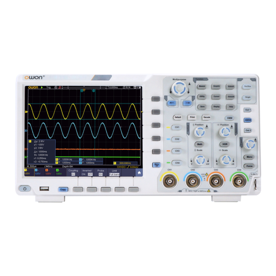
XDS3000 Dual-Channel Series
Digital Storage Oscilloscopes
User Manual
www.owon.com.cn
Table of
Contents
Previous
Page
Next
Page
1
2
3
4
5
Advertisement
Table of Contents
Need help?
Do you have a question about the XDS3204E and is the answer not in the manual?
Ask a question
Questions and answers
Related Manuals for Owon XDS3204E
Test Equipment Owon XDS3000-E Series User Manual
Four-channel digital storage oscilloscopes (149 pages)
Test Equipment Owon XDS3000 Series User Manual
Dual-channel digital storage oscilloscopes (157 pages)
Test Equipment Owon XDS3104A User Manual
Dual-channel digital storage oscilloscopes (156 pages)
Test Equipment Owon XDS3204AE Manual
(43 pages)
Test Equipment Owon XDS4000 Series User Manual
Digital storage oscilloscopes (145 pages)
Test Equipment Owon XDS4000 Series Quick Manual
Digital storage oscilloscopes (40 pages)
Test Equipment Owon XDS3104 User Manual
Digital storage oscilloscopes (156 pages)
Test Equipment Owon XDS2000 Series User Manual
Dual-channel digital storage oscilloscopes (113 pages)
Test Equipment Owon XDS Series User Manual
Dual-channel digital storage oscilloscopes (113 pages)
Test Equipment Owon XDS2102A User Manual
Dual-channel digital storage oscilloscopes (113 pages)
Test Equipment Owon XDS2102 User Manual
Dual-channel digital storage oscilloscopes (113 pages)
Test Equipment Owon XDS2202 User Manual
Dual-channel digital storage oscilloscopes (113 pages)
Test Equipment Owon AG4151 User Manual
Arbitrary waveform generator (52 pages)
Test Equipment Owon MSO series User Manual
Portable mixed signal digital storage oscilloscope (108 pages)
Test Equipment Owon SDS series User Manual
Sds series smart digital storage oscilloscopes (98 pages)
Test Equipment Owon PDS5022S User Manual
Pds series portable colour digital storage oscilloscope (93 pages)
This manual is also suitable for:
Xds3062a
Xds3102
Xds3102a
Xds3102ap
Xds3202e
Xds3202a
...
Show all
Xds3202
Xds3302
Xds3000 dual-channel series
Xds3204ae
Xds3104e
Xds3104
Xds3064e
Xds3064ae
Xds3104ae
Table of Contents
Print
Rename the bookmark
Delete bookmark?
Delete from my manuals?
Login
Sign In
OR
Sign in with Facebook
Sign in with Google
Upload manual
Upload from disk
Upload from URL


Need help?
Do you have a question about the XDS3204E and is the answer not in the manual?
Questions and answers