Table of Contents
Advertisement
Quick Links
General Warranty
OWON warrants that the product will be free from defects in materials and workmanship
for a period of 3 years from the date of purchase of the product by the original purchaser
from the OWON Company. The warranty period for accessories such as probes, battery is
12 months. This warranty only applies to the original purchaser and is not transferable to a
third party.
If the product proves defective during the warranty period, OWON will either repair the
defective product without charge for parts and labour, or will provide a replacement in
exchange for the defective product. Parts, modules and replacement products used by
OWON for warranty work may be new or reconditioned like new. All replaced parts,
modules and products become the property of OWON.
In order to obtain service under this warranty, the customer must notify OWON of the
defect before the expiration of the warranty period. Customer shall be responsible for
packaging and shipping the defective product to OWON's designated service centre, a
copy of the customers proof of purchase is also required.
This warranty shall not apply to any defect, failure or damage caused by improper use or
improper or inadequate maintenance and care. OWON shall not be obligated to furnish
service under this warranty a) to repair damage resulting from attempts by personnel other
than OWON representatives to install, repair or service the product; b) to repair damage
resulting from improper use or connection to incompatible equipment; c) to repair any
damage or malfunction caused by the use of non-OWON supplies; or d) to service a
product that has been modified or integrated with other products when the effect of such
modification or integration increases the time or difficulty of servicing the product.
Please contact the nearest OWON's Sales and Service Offices for services or a complete
copy of the warranty statement.
For better after-sales service, please visit
www.owon.com.cn
and register the purchased
product online.
Excepting the after-sales services provided in this summary or the applicable warranty
statements, OWON will not offer any guarantee for maintenance definitely declared or hinted,
including but not limited to the implied guarantee for marketability and special-purpose
acceptability. OWON should not take any responsibilities for any indirect, special or consequent
damages.
This quick guide is only for reference. Visit
www.owon.com.cn
to get the latest version of
user manual.
Advertisement
Table of Contents

Related Manuals for Owon XDS3204AE


Summary of Contents for Owon XDS3204AE
- Page 1 OWON for warranty work may be new or reconditioned like new. All replaced parts, modules and products become the property of OWON. In order to obtain service under this warranty, the customer must notify OWON of the defect before the expiration of the warranty period. Customer shall be responsible for packaging and shipping the defective product to OWON's designated service centre, a copy of the customers proof of purchase is also required.
-
Page 2: Table Of Contents
Table of Contents 1. General Safety Requirements ..................1 2. Safety Terms and Symbols ....................2 3. Quick Start ........................4 Introduction to the Structure of the Oscilloscope ..............4 Front Panel ............................. 4 Rear Panel ............................... 5 Control Area ............................6 User Interface Introduction ...................... - Page 3 6. Communication with PC ....................26 Using USB Port .......................... 27 Using LAN Port ......................... 27 Connect directly ............................ 27 Connect through a router ........................29 Using Wi-Fi to Connect with PC (Optional) ................31 Connect with PC as Wi-Fi Access Point ..................... 31 Connect with PC as Wi-Fi Station ......................
-
Page 4: General Safety Requirements
1.General Safety Requirements 1. General Safety Requirements Before use, please read the following safety precautions to avoid any possible bodily injury and to prevent this product or any other connected products from damage. In order to avoid any contingent danger, ensure this product is only used within the range specified. -
Page 5: Safety Terms And Symbols
2.Safety Terms and Symbols 2. Safety Terms and Symbols Safety Terms Terms in this manual. The following terms may appear in this manual: Warning: Warning indicates the conditions or practices that could result in injury or loss of life. Caution: Caution indicates the conditions or practices that could result in damage to this product or other property. - Page 6 2.Safety Terms and Symbols The diagram of the oscilloscope ground wire connection: Probe Oscilloscope Electrical Outlet Signal Input Power Cord Ground Clip The diagram of the ground wire connection when the battery-powered oscilloscope is connected to the AC-powered PC through the ports: Oscilloscope Probe Electrical Outlet...
-
Page 7: Quick Start
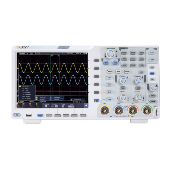
3.Quick Start 3. Quick Start Introduction to the Structure of the Oscilloscope This chapter makes a simple description of the operation and function of the front panel of the oscilloscope, enabling you to be familiar with the use of the oscilloscope in the shortest time. -
Page 8: Rear Panel
3.Quick Start 8. Copy button: You can save the waveform by just pressing this button in any user interface. 9. USB Host port: It is used to transfer data when external USB equipment connects to the oscilloscope regarded as "host device". For example: Saving the waveform to USB flash disk needs to use this port. -
Page 9: Control Area
3.Quick Start Control Area Figure 3-3 Control Area Overview 1. Function button area: Total 11 buttons 2. Waveform generator controls (optional) DAQ: Multimeter Recorder P/F: Pass/Fail W.REC: Waveform Record 3. Trigger control area with 2 buttons and 1 knob. The Trigger Level knob is to adjust trigger voltage. Other 2 buttons refer to trigger system setting. -
Page 10: User Interface Introduction
3.Quick Start the menu on the left and right. User Interface Introduction Figure 3-4 Illustrative Drawing of Display Interfaces Waveform Display Area. 2. Run/Stop (touchable on touchscreen) 3. The state of trigger, including: Auto: Automatic mode and acquire waveform without triggering. Trig: Trigger detected and acquire waveform. - Page 11 3.Quick Start (only for touchscreen). 11. It shows setting time. 12. WI-FI is activated. 13. It indicates that there is a USB disk connecting with the oscilloscope. 14. Indicating battery power status. 15. Multimeter window. 16. The waveform of CH1. 17.
-
Page 12: How To Implement The General Inspection
Manual. You can check whether there is any loss of accessories with reference to this description. If it is found that there is any accessory lost or damaged, please get in touch with the distributor of OWON responsible for this service or the OWON's local offices. -
Page 13: How To Implement The Probe Compensation
3.Quick Start probe on the menu is 10X. Set the Switch in the Oscilloscope Probe as 10X and Connect the Oscilloscope with CH1 Channel. Align the slot in the probe with the plug in the CH1 connector BNC, and then tighten the probe with rotating it to the right side. -
Page 14: How To Set The Probe Attenuation Coefficient
3.Quick Start 2. Check the displayed waveforms and regulate the probe till a correct compensation is achieved (see Figure 3-6 and Figure 3-7). Overcompensated Compensated correctly Under compensated Figure 3-6 Displayed Waveforms of the Probe Compensation Repeat the steps mentioned if needed. Figure 3-7 Adjust Probe How to Set the Probe Attenuation Coefficient The probe has several attenuation coefficients, which will influence the vertical scale... -
Page 15: How To Use The Probe Safely
3.Quick Start Figure 3-8 Attenuation Switch Caution: When the attenuation switch is set to 1X, the probe will limit the bandwidth of the oscilloscope in 5MHz. To use the full bandwidth of the oscilloscope, the switch must be set to 10X. How to Use the Probe Safely The safety guard ring around the probe body protects your finger against any electric shock, shown as Figure 3-9. -
Page 16: Introduction To The Vertical System
3.Quick Start in the left menu, select Self Cal in the bottom menu; run the program after everything is ready. Introduction to the Vertical System As shown in Figure 3-10, there are a few of buttons and knobs in Vertical Controls. The 4 channels are marked by different colors which are also used to mark both the corresponding waveforms on the screen and the channel input connectors. -
Page 17: Introduction To The Horizontal System
3.Quick Start If the channel is under the AC mode, the DC component would be filtered out. This mode helps you display the AC component of the signal with a higher sensitivity. Vertical offset back to 0 shortcut key Turn the Vertical Position knob to change the vertical display position of the selected channel, and push the position knob to set the vertical display position back to 0 as a shortcut key, this is especially helpful when the trace position is far out of the screen and want it to get back to the screen center immediately. -
Page 18: Introduction To The Trigger System
3.Quick Start Triggering displacement back to 0 shortcut key Turn the Horizontal Position knob to change the horizontal position of channel and push the Horizontal Position knob to set the back to 0 triggering displacement as a shortcut key. 3. Push the Horizontal HOR button to switch between the normal mode and the wave zoom mode. - Page 19 3.Quick Start waveform sampling. Autoset: Click the on the left top of the display area to auto set. Select a menu item: Touch the menu items in the bottom menu, or in the right menu, or in the left menu. ...
- Page 20 3.Quick Start Channel pointer Selected Unselected Channel is on and selected Channel is off Channel is on Set the horizontal and vertical position Click in the area as shown in the figure below, the P icon will appear. Click anywhere outside the icon to hide it.
- Page 21 3.Quick Start Set the trigger level Click in the area as shown in the figure below, the L icon will appear. Click anywhere outside the icon to hide it. Note: Swipe up/down in this area, you can make the icon appear and control it. When the L icon appears, in the full screen, swipe up/down to control the trigger level of the source in the trigger menu.
- Page 22 3.Quick Start When the M and V icons appear, in the full screen, swipe left/right to change the time base, swipe up/down to change the voltage division of the selected channel. Click the icons to fine-turn, long-press to adjust continuously. Control the Control the time base...
-
Page 23: How To Measure Automatically
3.Quick Start Cursor line Selected Unselected Switch horizontal or vertical lines If vertical lines are selected, drag up and down. When the C icon appears, in the full screen, swipe left/right to move the selected line. Click the direction buttons of the C icon to fine-turn, long-press to move continuously. Click the center "ab"... -
Page 24: How To Use Autoscale
4.Use the Arbitrary Function Generator (Optional) 5. In the right menu, select Add. The period type is added. 6. In the left Type menu, turn the M knob to select Frequency. 7. In the right menu, select Source as CH1. 8. -
Page 25: To Set Channels
4.Use the Arbitrary Function Generator (Optional) Figure 4-1 Generator Output Ports To see the output of the generator, connect the other end of the BNC cable to one of the input channels on the front of the oscilloscope. To Set Channels To Switch Channels in Menu Settings Push button to switch between CH1 menu, CH2 menu, and Channel Copy menu. -
Page 26: Create A New Waveform
4.Use the Arbitrary Function Generator (Optional) Clear Units Use the touchscreen (Touchscreen is optional): Click to increase the value of cursor position Click to show the Move the cursor soft keyboard Click to decrease the value of cursor position Parameters of waveforms Waveforms Menu Items... -
Page 27: File Browse
5.Use the Multimeter (Optional) (2) In the right menu, set the number of waveform points, the interpolation, and edit the waveform points. Save the waveform to internal storage or USB device. File Browse To read a waveform stored in internal storage or USB device: (1) Push button. -
Page 28: Dmm Menu
5.Use the Multimeter (Optional) DMM Menu Push the DMM button on the front panel to enter/exit the multimeter function. The button backlight will be lighted when the multimeter function is enabled. Figure 5-2 Multimeter Button The bottom menu of multimeter is as below: Menu Setting Description... -
Page 29: Communication With Pc
6.Communication with PC Figure 5-3 Multimeter Information Window Description 1. Manual/Auto range indicators, MANUAL refers to the measuring range in manual operation mode and AUTO refers to the measuring range in automatic operation mode. 2. Measurement mode indicators: ------ Current measurement ------ Voltage measurement ------... -
Page 30: Using Usb Port
6.Communication with PC Using USB Port (1) Connection: Use a USB data cable to connect the USB Device port in the right panel of the Oscilloscope to the USB port of a PC. (2) Install the driver: Run the Oscilloscope communication software on PC, push F1 to open the help document. - Page 31 6.Communication with PC Figure 6-2 Set the network parameters of the computer (3) Set the network parameters of the OWON Oscilloscope Software. Run the software on the computer; choose the "Ports-settings" of the "Communications" menu item. Set "Connect using" to LAN. About the IP, the first three bytes is same as the IP in the step (2), the last byte should be different.
-
Page 32: Connect Through A Router
6.Communication with PC button. Select Function in the bottom menu. Select LAN Set in the left menu. In the bottom menu, set the Type item as LAN, and select Set. In the right menu, set IP and Port to the same value as the "Ports-settings" in the software in step (3). Select Save set in the bottom menu, it prompts "Reset to update the config". - Page 33 6.Communication with PC Figure 6-5 Set the network parameters of the computer (3) Set the network parameters of the OWON Oscilloscope Software. Run the software on the computer; choose the "Ports-settings" of the "Communications" menu item. Set "Connect using" to LAN. About the IP, the first three bytes is same as the IP in the step (2), the last byte should be different.
-
Page 34: Using Wi-Fi To Connect With Pc (Optional)
6.Communication with PC button. Select Function in the bottom menu. Select LAN Set in the left menu. In the bottom menu, set the Type item as LAN, and select Set. In the right menu, set IP and Port to the same value as the "Ports-settings" in the software in step (3). The Gateway and Subnet mask should be set according to the router. -
Page 35: Connect With Pc As Wi-Fi Station
(7) Set Wi-Fi connection on PC. Enter the WI-FI settings on PC, select the oscilloscope access point to connect, enter the set password. (8) Set the network parameters of the OWON Oscilloscope Software. Run the software on the computer; choose the "Ports-settings" of the "Communications" menu item. - Page 36 6.Communication with PC Select LAN Set in the left menu. In the bottom menu, set the Type item as WIFI-STA, and select Set in the bottom menu. (2) In the right menu, select SSID, a keyboard will pop up. Input the name of the Wi-Fi hotspot.
- Page 37 6.Communication with PC Figure 6-9 Set the network parameters of the computer (8) Set the network parameters of the OWON Oscilloscope Software. Run the software on the computer; choose the "Ports-settings" of the "Communications" menu item. Set "Connect using" to LAN. Set IP and Port to the same value in the oscilloscope.
-
Page 38: Communication With Android Device Via Wi-Fi (Optional)
Android Versions: 4.0 and above Install the application software Install the free OWON application software, it can be downloaded from here: Scan the QR Code below with your Android based smart device. Follow the prompts on the download page to download and install the APP. - Page 39 6.Communication with PC password. WEP or WPA type need to set the password. You can select WPA. In the right menu, select Password, use the keyboard to set the Wi-Fi password (8 to 32 characters). (4) In the right menu, select IP:PORT, IP is fixed by the oscilloscope, and can not be edited.
-
Page 40: Connect With App As Wi-Fi Station
6.Communication with PC (10) Set IP and Port to the same value as the setting in the oscilloscope. Click Confirm to connect. Click History to recall the history settings. Connect with APP as Wi-Fi Station (1) In the oscilloscope, push the Utility button. Select Function in the bottom menu. Select LAN Set in the left menu. - Page 41 6.Communication with PC (6) Select Save set in the bottom menu to save current settings. (7) In Android device, enter the Wi-Fi settings, select the oscilloscope access point to connect, enter the set password. (8) In Android device, launch the application. (9) Click connect on the left.
-
Page 42: Appendix
8.Appendix 8. Appendix Appendix A: Enclosure (The accessories subject to final delivery.) Standard Accessories: Power Cord CD Rom Quick Guide USB Cable Probe Probe Adjust Options: Multimeter Lead Capacitance Battery Soft Bag Ext Module Appendix B: General Care and Cleaning General Care Do not store or leave the instrument where the liquid crystal display will be exposed to direct sunlight for long periods of time. -
Page 43: Appendix C: Usb Disk Requirements
4K, mass storage USB disk is also supported. If the USB disk doesn't work properly, format it into the supported format and try again. To learn how to format the USB disk, please refer to the User Manual. You can get this manual from the supplied CD or visit www.owon.com.cn 2017.07 V1.0.0...
Need help?
Do you have a question about the XDS3204AE and is the answer not in the manual?
Questions and answers