Table of Contents
Advertisement
Quick Links
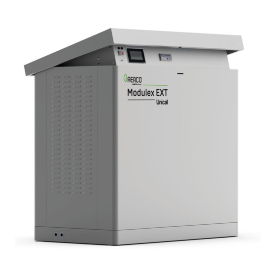
Installation, Operation & Maintenance Manual
Modulex EXT – Ufly Controller
Commercial Series
Modulating and Condensing Boilers
Applies To Modulex Models:
• MLX EXT 1500 2S
• MLX EXT 2300 2S
• MLX EXT 2600 2S
• MLX EXT 3000 2S
Disclaimer
The information contained in this manual is subject to change without notice
from AERCO International, Inc. AERCO makes no warranty of any kind with
respect to this material, including, but not limited to, implied warranties of
merchantability and fitness for a particular application. AERCO International is
not liable for errors appearing in this manual, not for incidental or
consequential damages occurring in connection with the furnishing,
performance, or use of these materials.
• 6/28/2022
OMM-0160_A
Heating and Hot Water Solutions
AERCO International, Inc. • 100 Oritani Drive • Blauvelt, NY 10913
USA: T: (845) 580-8000 • Toll Free: (800) 526-0288 • AERCO.com
Technical Support • (800) 526-0288 • Mon-Fri, 8 am - 5 pm EST
© 2022 AERCO
Advertisement
Table of Contents

Related Manuals for Watts AERCO EXT


![Controller Watts AERCO Edge [ii] Operation Manual](https://static-data2.manualslib.com/product-images/da1/2085997/60x60/watts-aerco-edge-ii-controller.jpg)


Summary of Contents for Watts AERCO EXT
- Page 1 Installation, Operation & Maintenance Manual Modulex EXT – Ufly Controller Commercial Series Modulating and Condensing Boilers Applies To Modulex Models: • MLX EXT 1500 2S • MLX EXT 2300 2S • MLX EXT 2600 2S • MLX EXT 3000 2S Disclaimer The information contained in this manual is subject to change without notice from AERCO International, Inc.
-
Page 2: Table Of Contents
Modulex EXT Commercial Series CONTENTS Table of Contents CHAPTER 1: SAFETY PRECAUTIONS ....................6 CHAPTER 2: GENERAL INFORMATION .................... 10 2.1 Correct Use of The Appliance ........................10 2.2 Water Treatment ............................10 2.3 Information To Be Made Available to The User .................... 10 2.4 Safety Warnings ............................ - Page 3 Modulex EXT Commercial Series CONTENTS Propane Gas Piping Sizes ....................... 29 Propane Gas Piping Connections ....................29 Propane Gas Supply Pressure Requirements .................. 29 4.10 Flow And Return Pipe Connections ......................29 4.11 Pressure Relief Valve ..........................30 4.12 CSD-1 Manifold Assembly (Supplied) ......................30 4.13 Determination Of Primary Boiler Pump or Boiler System Pump..............
- Page 4 Modulex EXT Commercial Series CONTENTS 5.1 Ufly Controller ............................67 5.1.1 Ufly Controller Features and Functions ..................... 67 5.1.2 Reading the Icons on Home Page ...................... 68 5.1.3 Display Modes ..........................69 5.2 BCM (BOILER COMMUNICATION MODULE) ....................69 CHAPTER 6: OPERATION, MENU & PARAMETERS ................. 73 6.1 SETUP MENU ..............................
- Page 5 Modulex EXT Commercial Series CONTENTS (This Page Intentionally Blank) OMM-0160_A • DRAFT Technical Support • (800) 526-0288 • Mon-Fri, 8 am - 5 pm EST Page 5 of 117...
-
Page 6: Chapter 1: Safety Precautions
Modulex EXT Commercial Series CHAPTER 1: SAFETY PRECAUTIONS CHAPTER 1: SAFETY PRECAUTIONS The following defined symbols are used throughout this manual to notify the reader of potential hazards of varying risk levels. D A N G E R ! Indicates an imminent hazard which if not avoided WILL result in death or serious injury. W A R N I N G ! Indicates a potentially hazard which if not avoided MAY result in death or serious injury. - Page 7 Modulex EXT Commercial Series CHAPTER 1: SAFETY PRECAUTIONS the Fill/Makeup Valve. • The vent termination must be located a minimum of 4 feet above grade level. • If side-wall venting is used, the installation must conform to the following requirements extracted from 248 CMR 5.08 (2): A.
- Page 8 Modulex EXT Commercial Series CHAPTER 1: SAFETY PRECAUTIONS Important - For Massachusetts Installations (Continued from Previous Page) B. EXEMPTIONS: The following equipment is exempt from 248 CMR 5.08(2)(a)1 to 4: 1. The equipment listed in Chapter 10 entitled "Equipment Not Required To Be Vented" in the most current edition of NFPA 54 as adopted by the Board;...
- Page 9 Modulex EXT Commercial Series CHAPTER 1: SAFETY PRECAUTIONS (This page intentionally blank) OMM-0160_A • DRAFT Technical Support • (800) 526-0288 • Mon-Fri, 8 am - 5 pm EST Page 9 of 117...
-
Page 10: Chapter 2: General Information
Modulex EXT Commercial Series CHAPTER 2: General Information CHAPTER 2: GENERAL INFORMATION 2.1 Correct Use of the Appliance The MODULEX EXT Commercial boiler has been designed utilizing the latest heating technologies and in compliance with current safety regulations. However, if not used or operated properly, the unit may cause injury or death to persons, or serious damage to the equipment or surrounding objects. -
Page 11: Safety Warnings
Modulex EXT Commercial Series CHAPTER 2: General Information 2.4 Safety Warnings W A R N I N G ! Children must be supervised so they do not play on, around, or with the appliance. The installation, adjustment, and servicing of this appliance must be carried out by a competent person and installed in accordance with the current standards and regulations. -
Page 12: Data Plate
Modulex EXT Commercial Series CHAPTER 2: General Information 2.7 Data Plate A sample Data Plate for a MODULEX EXT Commercial boiler is shown in the left figure below. A sample of the Data Packaging label is shown in the right image below. Figure 2-1: MODULEX EXT Commercial Data Plate (L) and Data Packing Label (R) Each unit is fitted with a data plate, which may be consulted for the details on gas type, power source, and venting classification. -
Page 13: Operational Requirements
Modulex EXT Commercial Series CHAPTER 2: General Information 2.8 Operational Requirements 2.8.1 General Requirements The following instructions MUST be followed: • The boiler must only be used for its designated purpose as described herein. • Each unit is fitted with a data plate. Consult the details on this plate to verify whether the boiler is compliant with its intended location, e.g.: gas type, power source, and venting classification. -
Page 14: Water Quality Requirements
Modulex EXT Commercial Series CHAPTER 2: General Information 2.8.3 Water Quality Requirements NOTE: For additional information concerning water quality and treatment, refer to AERCO technical documents Glycol Directive and AERCO Piping Application Guide (GF-136-P). Unsuitable heating system water can cause the formation of scale or sludge, which affects system efficiency. -
Page 15: Disposal Of Packaging And Parts
Modulex EXT Commercial Series CHAPTER 2: General Information 2.10 Disposal Of Packaging and Parts • Dispose of the boiler packaging in an environmentally sound manner. • Dispose of components of the heating system (e.g. boiler or control device), that must be replaced in an environmentally responsible manner. -
Page 16: Chapter 3: Technical Features & Dimensions
Modulex EXT Commercial Series CHAPTER 3: Technical Features & Dimensions CHAPTER 3: TECHNICAL FEATURES & DIMENSIONS 3.1 MODULEX EXT Commercial Technical Features • Compact, gas fired, Low NO , condensing boiler. • Comprised of one sectional boiler body, suitable as a single boiler or in a cascaded group. •... -
Page 17: General Boiler Operation
Modulex EXT Commercial Series CHAPTER 3: Technical Features & Dimensions • Operation modes: o Ability to control power to the individual heating elements for any calibration with or without confidential code access. o Production of A.C.S. (Active Cooling System) by NTC sensor of priorities for control by boiler feed pump or by three-way diverter valve controller. -
Page 18: Dimensional Drawings
Modulex EXT Commercial Series CHAPTER 3: Technical Features & Dimensions 3.4 Dimensional Drawings Figure 3-1: MODULEX EXT Commercial Dimensional Drawings OMM-0160_A • DRAFT Technical Support • (800) 526-0288 • Mon-Fri, 8 am - 5 pm EST Page 18 of 117... - Page 19 Modulex EXT Commercial Series CHAPTER 3: Technical Features & Dimensions TABLE 3-1: MODULEX EXT Commercial Dimensions and Sizes OMM-0160_A • DRAFT Technical Support • (800) 526-0288 • Mon-Fri, 8 am - 5 pm EST Page 19 of 117...
- Page 20 Modulex EXT Commercial Series CHAPTER 3: Technical Features & Dimensions Figure 3-2: MODULEX EXT Commercial Main Components (Right Side View) No. S.E. Description No. S.E. Description Condensate drain tap E. RIL. Detection electrode Draining tap Limit Thermostat Probe Global return temp. sensor Burner Max air pressure switch Aluminum silicon heat exchanger...
-
Page 21: Performance Data
Modulex EXT Commercial Series CHAPTER 3: Technical Features & Dimensions 3.5 Performance Data Model MODULEX EXT 1500 2S 2300 2S 2600 2S 3000 2S Min. heat input 83,300 Btu/hr (24.4 kW) Nominal heat input 1,530,000 Btu/hr 2,295,000 Btu/hr 2,677,000 Btu/hr 784.6 kW 3,060,000 Btu/hr (low altitude) 448.4 kW 672.7 kW... -
Page 22: Chapter 4: Installation Instructions
Modulex EXT Commercial Series CHAPTER 4: Installation Instructions CHAPTER 4: INSTALLATION INSTRUCTIONS 4.1 Installation Warnings and Requirements 4.1.1 Appropriate Use of the Boiler This boiler MUST be used in the application for which it has been expressly designed. Any other use shall be considered improper and therefore dangerous. -
Page 23: Code And Standards Approvals
Modulex EXT Commercial Series CHAPTER 4: Installation Instructions 4.2 Code And Standards Approvals The MODULEX EXT boiler has been reviewed for compliance with the applicable sections of the following North American Standards: • ANSI Z21.13/CSA 4.9: Gas-fired low pressure steam and hot water boilers •... -
Page 24: Transporting And Securing The Boiler Safely
Modulex EXT Commercial Series CHAPTER 4: Installation Instructions 4.4 Transporting And Securing the Boiler Safely The boiler is susceptible to serious damage if not secured properly. • Follow the transportation instructions on the packaging. • Only transport the boiler using appropriate transportation equipment, such as a hand-truck with a fastening belt or special equipment for transporting heavy equipment. -
Page 25: Boiler Package Contents
Modulex EXT Commercial Series CHAPTER 4: Installation Instructions 4.6 Boiler Package Contents In the packaging, in addition to the boiler, you will also find the following contents: ON THE LEFT HAND SIDE OF BOILER (UNDER PANEL) • CSD-1 manifold • Relief Valve CARDBOARD BOX #1 •... -
Page 26: Location In Boiler Room
Modulex EXT Commercial Series CHAPTER 4: Installation Instructions 4.7 Location in Boiler Room Pay special attention to local regulations and laws about boiler enclosures and boiler rooms, particularly to the minimum clearances around the boiler. The installation must be in compliance with all regulations and laws about boiler enclosures, boiler rooms, installations of heating and hot-water systems, ventilation, and any other applicable requirements. -
Page 27: Products To Avoid In The Boiler Room
Modulex EXT Commercial Series CHAPTER 4: Installation Instructions 4.7.2 Products to Avoid in the Boiler Room Do NOT store the following in the boiler room and/or around combustion air intake vents. • Spray cans containing chlorocarbons/fluorocarbons • Ammonium and/or ammonium solutions •... -
Page 28: Gas Connection General Information
Modulex EXT Commercial Series CHAPTER 4: Installation Instructions 4.9 Gas Connection General Information For natural gas connections see Section 4.9.1. For propane gas, see Section 4.9.2. The gas supply connection must comply with local regulations or, if such regulations do not exist, with the National Fuel Gas Code, ANSI Z223.1/NFPA 54. -
Page 29: Natural Gas Connections
Modulex EXT Commercial Series CHAPTER 4: Installation Instructions 4.9.1 Natural Gas Connections Natural Gas Piping Sizes Contact your local gas supplier for natural gas pipe sizes and meter types. Natural Gas Piping Connections The boiler gas pipe is equipped with external 3’’ ASME B16.5 flange, onto which the tail piece of the gas shut off valve can be connected. -
Page 30: Pressure Relief Valve
Modulex EXT Commercial Series CHAPTER 4: Installation Instructions W A R N I N G ! Before installing the boiler, we recommend that the system is flushed out with a suitable cleaning product in order to eliminate any metallic tooling or welding residues, or oil and grime, which could reach the boiler and affect the proper functioning of the boiler. - Page 31 Modulex EXT Commercial Series CHAPTER 4: Installation Instructions 1-1/2” Pressure Relief Valve Flow Switch Pressure/ Temperature Gauge Figure 4-5: CSD-1 Manifold Assembly and Components Complete the instructions below to install the pressure relief valve and the other components. NOTE: Use Teflon tape or a suitable pipe joint compound for component and piping connections. Installing the Pressure Relief Valve and Flow Switch Attach manifold to the outlet supply connection on the boiler via the flanged connections.
-
Page 32: Determination Of Primary Boiler Pump Or Boiler System Pump
Modulex EXT Commercial Series CHAPTER 4: Installation Instructions Figure 4-6: BMM Location and Flow Switch Connection 4.13 Determination Of Primary Boiler Pump or Boiler System Pump ∆t The following table gives an indication of the pump’s flow rate in function of the of the primary circuit if the installation has a mixing header. -
Page 33: Condensate Piping And Drain
Modulex EXT Commercial Series CHAPTER 4: Installation Instructions TABLE 4-2: MODULEX EXT Minimum/Maximum Flow Rates BOILER MODEL EXT 1500 2S EXT 2300 2S EXT 2600 2S EXT 3000 2S Min. flow rate demanded in gpm ∆T 27°F (15°C) Min. flow rate demanded in gpm ∆T 36°F (20°C) Max flow rate demanded in gpm ∆T 27°F (15°C) - Page 34 Modulex EXT Commercial Series CHAPTER 4: Installation Instructions to evacuate the condensate through an open gutter to prevent the risk of ice forming and avoid exposure of the corrosive condensate to the external environment. The condensate must be neutralized before being evacuated to the sewer, which can be achieved by mixing the condensate with lime or with drain water coming from washing machines, dish washing machines, etc., which normally has a base pH.
-
Page 35: Water Treatment
Modulex EXT Commercial Series CHAPTER 4: Installation Instructions 4.15 Water Treatment The chemical/physical composition of the heating system’s water is fundamental to the boiler’s correct operation and safety. Among the problems caused by poor quality of feed water, the most frequent and most serious is the buildup of deposits on boiler thermal exchange surfaces. -
Page 36: Connection To Refrigeration System Warning
Modulex EXT Commercial Series CHAPTER 4: Installation Instructions 4.16.4 Connection to Refrigeration System Warning The boiler, when used in connection with a refrigeration system, must be installed so the chilled medium is piped in parallel with the boiler with appropriate valves to prevent the chilled medium from entering the boiler. - Page 37 Modulex EXT Commercial Series CHAPTER 4: Installation Instructions RECTANGULAR GASKET Washers (10) Nuts (10) Flue Manifold Gasket For Attaching European-To-American Flue Adapter Figure 4-10: Connection of Exhaust Manifold to Boiler Flue Exhaust Outlet For venting systems in the USA, it is necessary to assemble the Euro-to-USA adaptor to the flue manifold as shown in Figure 4-11.
-
Page 38: Flue Exhaust Piping To Vent
Modulex EXT Commercial Series CHAPTER 4: Installation Instructions 4.19 Flue Exhaust Piping to Vent In a condensing boiler the flue exhaust is evacuated at a very low temperature (maximum of about 183°F / 84°C). Thus, it is necessary that the chimney be impermeable to the condensate of the combustion products and be made of corrosion resistant materials. -
Page 39: Vent Starter Pieces
Modulex EXT Commercial Series CHAPTER 4: Installation Instructions 4.20 Vent Starter Pieces All vent starter pieces for the MODULEX EXT 1500 through 3060 can be purchased directly from the vent manufacturer. Example Vent Starter Piece WORM-DRIVEN HOSE CLAMP SCREWS (8 EACH) WASHERS (8 EACH) DIAMETER REDUCTION ADAPTOR CONNECTOR... -
Page 40: Combustion Air And Ventilation Openings
Modulex EXT Commercial Series CHAPTER 4: Installation Instructions B149.1, use vent systems that are certified to the standard for Type BH Gas Venting Systems, ULC- S636. Please note that 10” and 12” PVC can be heavy and expensive. Alternative vent materials, such as AL29-4C or polypropylene should be considered prior to installation. -
Page 41: Room Air Combustion
Modulex EXT Commercial Series CHAPTER 4: Installation Instructions Note the following: • Make sure that intake and exhaust openings are sufficiently sized and no reduction or closure of any openings takes place. • When a combustion air or ventilation problem is not resolved, do not operate the boiler. When contaminated combustion air is expected (near swimming pools, chemical cleaning operations, hair salons, etc.), sealed combustion operation is recommended. -
Page 42: Installing The Exhaust And Air Intake System
Modulex EXT Commercial Series CHAPTER 4: Installation Instructions 4.22 Installing the Exhaust and Air Intake System NOTE: Consult local and state codes pertaining to special building code and fire department requirements. Adhere to national code requirements. Observe the listed maximum lengths of vent system which are boiler model dependent. The maximum permissible lengths are listed in Section 4.23. -
Page 43: Minimum And Maximum Wall Thickness
Modulex EXT Commercial Series CHAPTER 4: Installation Instructions The terminal should be located where dispersal of combustion products is not impeded and with due regard for the damage or discoloration that might occur to building surfaces in the vicinity. In certain weather conditions condensation may also accumulate on the outside of the air inlet pipe. - Page 44 Modulex EXT Commercial Series CHAPTER 4: Installation Instructions Figure 4-16: MODULEX EXT Allowable Venting Solution Examples OMM-0160_A • DRAFT Technical Support • (800) 526-0288 • Mon-Fri, 8 am - 5 pm EST Page 44 of 117...
-
Page 45: Electrical Connections
Modulex EXT Commercial Series CHAPTER 4: Installation Instructions 4.24 Electrical Connections 4.24.1 Regulations in Force The electrical connections to the boiler must be made in accordance with all applicable local codes and the latest revision of the National Electrical Code, ANSI/NFPA-70. Installations should conform with CSA C22.1 Canadian Electrical Code Part 1, if installed in Canada. -
Page 46: Service Relay Requirement
Modulex EXT Commercial Series CHAPTER 4: Installation Instructions W A R N I N G ! DANGER OF FATAL ACCIDENT DUE TO ELECTRIC SHOCK! 120 VAC connections may be present on the external connection board when power is supplied to the boiler. The electrical connections must be carried out only by a qualified person. - Page 47 Modulex EXT Commercial Series CHAPTER 4: Installation Instructions Figure 4-18: Main Power Junction Box Location and 120VAC Wiring OMM-0160_A • DRAFT Technical Support • (800) 526-0288 • Mon-Fri, 8 am - 5 pm EST Page 47 of 117...
-
Page 48: Functional Wiring Diagram
Modulex EXT Commercial Series CHAPTER 4: Installation Instructions 4.25 Functional Wiring Diagram page 1 OMM-0160_A • DRAFT Technical Support • (800) 526-0288 • Mon-Fri, 8 am - 5 pm EST Page 48 of 117... -
Page 49: Functional Wiring Diagram
Modulex EXT Commercial Series CHAPTER 4: Installation Instructions 4.26 Functional Wiring Diagram, page 2 OMM-0160_A • DRAFT Technical Support • (800) 526-0288 • Mon-Fri, 8 am - 5 pm EST Page 49 of 117... -
Page 50: Module Ladder Diagram
Modulex EXT Commercial Series CHAPTER 4: Installation Instructions 4.27 Module Ladder Diagram Figure 4-19: Module Ladder Diagram OMM-0160_A • DRAFT Technical Support • (800) 526-0288 • Mon-Fri, 8 am - 5 pm EST Page 50 of 117... -
Page 51: General Ladder Diagram
Modulex EXT Commercial Series CHAPTER 4: Installation Instructions 4.28 General Ladder Diagram Figure 4-20: General Ladder Diagram OMM-0160_A • DRAFT Technical Support • (800) 526-0288 • Mon-Fri, 8 am - 5 pm EST Page 51 of 117... -
Page 52: Input/Output Box Terminal Assignments
Modulex EXT Commercial Series CHAPTER 4: Installation Instructions 4.29 Input/Output Box Terminal Assignments Heating system components such as pump, outside air sensor and flow switch must be connected to the Input/Output box. Alarm contact, analog control input (0--10V) and Modbus communication are also connected to the Input/Output box. -
Page 53: Starting Up: Filling And De-Aerating The Boiler
Modulex EXT Commercial Series CHAPTER 4: Installation Instructions Figure 4-21b: Sensor and BCM Terminal Assignments 4.30 Starting Up: Filling and De-Aerating The Boiler Carry out the following tasks in connection with maintenance, etc. to an already installed unit: • Shut down all programs •... -
Page 54: Filling Locations And Preparation
Modulex EXT Commercial Series CHAPTER 4: Installation Instructions Before filling the heating system, the complete system, including all zones, must be thoroughly cleaned and flushed to remove sediment. Flush until clean water runs free of sediment. AERCO suggests using an approved system cleaner to flush the system, but not the boiler. - Page 55 Modulex EXT Commercial Series CHAPTER 4: Installation Instructions FOR YOUR SAFETY READ BEFORE OPERATING WARNING: If you do not follow these instructions, a fire or explosion may result causing property damage, personal injury, or loss of life. A. This appliance does not have a pilot light. It is equipped with an ignition device, which automatically lights the burner.
-
Page 56: Testing The Ignition Safety Shut-Off Device
Modulex EXT Commercial Series CHAPTER 4: Installation Instructions 4.32 Testing The Ignition Safety Shut-Off Device 1. Power on by switching on the ON-OFF switch. 2. Create a request in C/H Central Heating. 3. Turn burners ON. 4. Disconnect the plug and socket connection of the ionization cable (WHITE) of BURNER 1. 5. -
Page 57: Burner Calibration
Modulex EXT Commercial Series CHAPTER 4: Installation Instructions 4.33 Burner Calibration W A R N I N G ! All the instructions indicated below are for the exclusive use of qualified AERCO service technicians or installers. All the boilers are supplied already calibrated and tested. However, if it is necessary to change the calibration due to gas conversion or adaptation to the mains supply system, the gas valve must be re-calibrated (using Service Mode in the Burner Menu of the Ufly Controller, see section 6.5. -
Page 58: Maximum Output Calibration
Modulex EXT Commercial Series CHAPTER 4: Installation Instructions REAR BOILER TOP VIEW FRONT Minimum Output Adjust Maximum Output Adjust Figure 4-23: Location of Minimum and Maximum Adjustments (Top View) 4.33.2 Maximum Output Calibration Locate the gas valves and the Maximum Gas Adjustment screw (A) on each valve. Follow the instructions below to set the maximum gas output level for each valve. -
Page 59: Minimum Output Calibration
Modulex EXT Commercial Series CHAPTER 4: Installation Instructions 4.33.3 Minimum Output Calibration After setting the maximum gas output for each valve (section 4.33.2), refer to Figure 4-24, above, to locate the Minimum Gas Adjustment screw (B) on each valve. Follow the instructions below to set the minimum gas output level for each valve. - Page 60 Modulex EXT Commercial Series CHAPTER 4: Installation Instructions TABLE 4-6: EXT Pressure, CO2 and O2 Level Calibration MODULEX EXT 1500 2S Type of Supply levels levels Ø Mixer Gas Consumption Start- Press. speed injectors output min. max. Minimum Maximum in w.c. Øin (mm) Min.
-
Page 61: Sweeper Mode (Manual Control)
Modulex EXT Commercial Series CHAPTER 4: Installation Instructions 4.34 Sweeper Mode (Manual Control) 1. Insert psw and select sweeper again. Vary % mod. request from 10% to 100%. 2. Activate Sweeper Mode. 3. Chose burner among those available, e.g.: usually 1 / Modulex (from 1 to 8). NOTE: Note: once selected the burner, (3) the display page changes: Burner # 1 .. - Page 62 Modulex EXT Commercial Series CHAPTER 4: Installation Instructions 5. Burner operating to maximum power 6. Vary % of modulation request to the (modulation 100%). minimum 10% and select the burner. 7. Boiler operating with modulation min. 8. Disable SWEEPER function. Exit by (modulation 0%).
-
Page 63: High Altitude Adjustment
Modulex EXT Commercial Series CHAPTER 4: Installation Instructions 4.35 High Altitude Adjustment It is necessary to adjust the fan speed at altitudes at or above 5,000 feet. Modify parameter 526 (FU: Fan maximum speed) of the BMM in the Devices Menu. NOTE: This is modifiable only with an access code. -
Page 64: High Altitude Conversion Label
Modulex EXT Commercial Series CHAPTER 4: Installation Instructions 4.36 High Altitude Conversion Label After calibration of the unit from Normal Altitude (0 - 2,000 feet) to High Altitude (2,000 – 4,500 feet) operation, the label below must be filled out with the appropriate information and applied to the unit in close proximity to the rating label. -
Page 65: Controls And Emergency Functions
Modulex EXT Commercial Series CHAPTER 4: Installation Instructions 4.38 Controls And Emergency Functions Figure 4-24: MODULEX EXT Panel Controls and Indicators Description MGNT Circuit Breaker LTGL TLG triggering lamp Manual reset main Limit Thermostat: when enabled, it cuts the power supply to the boiler and lights the warning ORANGE lamp (F) and description of the fault is displayed on User interface (E). - Page 66 Modulex EXT Commercial Series CHAPTER 4: Installation Instructions • All of the system’s on/off valves are in the appropriate position (open or closed as required) • The mains gas supply corresponds to the one which the boiler has been calibrated for. Otherwise convert the boiler to use the available gas (refer to section: “GAS CONVERSION”).
-
Page 67: Chapter 5: Ufly Controller & Bcm Modules
Modulex EXT Commercial Series CHAPTER 5: UFLY CONTROLLER & BCM MODULES CHAPTER 5: UFLY CONTROLLER & BCM MODULES MODULEX boilers contain advanced and reliable electronic controls, the Ufly Controller and the BCM (Boiler Communications Module), which provide comprehensive programming and monitoring of the MODULEX boiler and its functions. -
Page 68: Reading The Icons On Home Page
Modulex EXT Commercial Series CHAPTER 5: UFLY CONTROLLER & BCM MODULES 5.1.2 Reading the Icons on Home Page Heating: Access space heating parameters including setpoint, outdoor reset and building reference temperature. Domestic Hot Water: Access domestic hot water parameters including setpoint, timed programming, and legionella protection function Solar: This menu is currently not available. -
Page 69: Display Modes
Modulex EXT Commercial Series CHAPTER 5: UFLY CONTROLLER & BCM MODULES 5.1.3 Display Modes 6 Display Mode 7 Display Mode 8 Display Mode Screen Off Home Screen Menu Screen 5.2 BCM (BOILER COMMUNICATION MODULE) The BCM (Boiler Communication Module) is an electronic module in MODULEX boilers, which supports full interoperability to BAS (Building Automation Systems) via Modbus protocol to make remote communications and control possible. - Page 70 Modulex EXT Commercial Series CHAPTER 5: UFLY CONTROLLER & BCM MODULES Figure 5-1: Boiler Communications Module (BCM) Figure 5-2: BCM Key and LEDs Legend OMM-0160_A • DRAFT Technical Support • (800) 526-0288 • Mon-Fri, 8 am - 5 pm EST Page 70 of 117...
- Page 71 Modulex EXT Commercial Series CHAPTER 5: UFLY CONTROLLER & BCM MODULES (This page intentionally blank) OMM-0160_A • DRAFT Technical Support • (800) 526-0288 • Mon-Fri, 8 am - 5 pm EST Page 71 of 117...
-
Page 73: Chapter 6: Operation, Menu & Parameters
Modulex EXT Commercial Series CHAPTER 8: Maintenance Schedule CHAPTER 6: OPERATION, MENU & PARAMETERS This chapter introduces the Ufly controller basic menu contents needed to set up the MODULEX EXT boiler. For more detailed information concerning the Ufly controller menus, operating modes and functions, refer to the Ufly Controller User Manual (OMM-0159). -
Page 74: Setup Menu
Modulex EXT Commercial Series CHAPTER 8: Maintenance Schedule 6.1 SETUP MENU The Setup Menu allows the user to setup time and date, program Building Reference temperatures and domestic hot water setpoint, change display and language settings, and change the password for the Devices. 6.1.1 Setting Time and Date 6.1.2 Setting Comfort and Eco Building Reference Temperatures The Comfort and Eco Building Reference Temperatures for the Outdoor Reset Mode are... -
Page 75: Display Settings
Modulex EXT Commercial Series CHAPTER 8: Maintenance Schedule The Ufly screen automatically turns off after 20 seconds (default) of inactivity. If the "Always on" is toggled on like in the image below, the screen will remain on all the time. NOTE: Do not change the value of the Modbus address. -
Page 76: Password
Modulex EXT Commercial Series CHAPTER 8: Maintenance Schedule 6.1.6 Password For security and protection of the boiler, the default password is only availalbe to Authorized AERCO Service technicians. To Change the password: 1. Enter the current password and click OK 2. -
Page 77: Heating Menu
Modulex EXT Commercial Series CHAPTER 8: Maintenance Schedule 6.2 Heating Menu The Heating Menu provides access to Space Heating parameters including Outdoor Reset and Constant Setpoint Mode configurations. For Space Heating programming details, see sections 4.1 and 4.2 of the Control Manual OMM-0159. Ch13 Menu Comfort... -
Page 78: Domestic Hot Water Menu
Modulex EXT Commercial Series CHAPTER 8: Maintenance Schedule 6.3 Domestic Hot Water Menu The Domestic Hot Water Menu provides access to parameters to provide domestic hot water (DHW) using a tank sensor. For DHW programming details, see sections 4.4 of the Controls Manual OMM-0159. -
Page 79: Devices Menu
Modulex EXT Commercial Series CHAPTER 8: Maintenance Schedule 6.4 Devices Menu The Devices Menu allows access to BMM (Burner Management Module) parameters, BCM parameters for functions including 0-10V operation and domestic hot water operation, and error history. These parameters are for use by Authorized AERCO sercvice technicians only. Password is required to access this Menu. - Page 80 Modulex EXT Commercial Series CHAPTER 8: Maintenance Schedule Access and clear error history. OMM-0160_A • DRAFT Technical Support • (800) 526-0288 • Mon-Fri, 8 am - 5 pm EST Page 80 of 117...
-
Page 81: Burner Menu
Modulex EXT Commercial Series CHAPTER 8: Maintenance Schedule 6.5 Burner Menu The Burner Menu allows access to calibration, manual operation, and troubleshooting settings. This menu is password protected and is only for authorized AERCO technicians. 6.5.1 Service Mode/Manual Firing Rate Function 1. -
Page 82: Manual Setpoint Function
Modulex EXT Commercial Series CHAPTER 8: Maintenance Schedule 6.5.2 Manual Setpoint Function 1. Click on the Manual Setpoint button icon. This will show an Activate Button. 2. Toggling the Activate button allows user to operate the boiler with a manual setpoint. Any setpoint in the Heating or DHW Mode are ignored while the Manual Setpoint Function is activated. -
Page 83: Reset Burner Working Hours And Ignition Count
Modulex EXT Commercial Series CHAPTER 8: Maintenance Schedule 6.5.3 Reset Burner Working Hours and Ignition Count Select one of the available burners Click the Reset button. Password will be required to proceed. OMM-0160_A • DRAFT Technical Support • (800) 526-0288 • Mon-Fri, 8 am - 5 pm EST Page 83 of 117... -
Page 84: Bcm Parameters
Modulex EXT Commercial Series CHAPTER 8: Maintenance Schedule 6.6 BCM Parameters This section provides the list of the parameters in the BCM. See Section 6.4 for instructions on how to navigate to the BCM parameters. PARAMETER DESCRIPTION ENTRY RANGE DEFAULT Enabled services 16 = Control via Modbus* 17 = Heating only... - Page 85 Modulex EXT Commercial Series CHAPTER 8: Maintenance Schedule PARAMETER DESCRIPTION ENTRY RANGE DEFAULT Pump: minimum control 0-10V (Minimum output pump modulation) See Controls Manual OMM-0159 Section 6.4.3 Pump: maximum control 0-10V (Maximum output pump modulation) See Controls Manual OMM-0159 Section 6.4.3 CH Maximum modulation 0-100% 100%...
- Page 86 Modulex EXT Commercial Series CHAPTER 8: Maintenance Schedule PARAMETER DESCRIPTION ENTRY RANGE DEFAULT CH#1: parallel DHW (Heating/DHW Parallel Operation) 0 = DHW demand is priority, Parallel Operation is disabled. 1 = Parallel operation of space heating See Description and DHW is allowed provided the Boost Temperature setpoint (Param.
- Page 87 Modulex EXT Commercial Series CHAPTER 8: Maintenance Schedule PARAMETER DESCRIPTION ENTRY RANGE DEFAULT System configuration (Application Code) See Description 0 = Burner cascade (BMM) 1 = DO NOT USE Programmable Relay #1 (BCM Y4-1/2) Function (BCM connector Y4, terminals 1 and 2) 0 = Primary Pump (boiler loop) control See Description 1 = Boiler status contact (closes when at...
-
Page 88: Bmm Parameters
Modulex EXT Commercial Series CHAPTER 8: Maintenance Schedule 6.7 BMM Parameters This section provides the list of the parameters in the BMM (Burner Management Module) boards. See Section 6.4 for instructions on how to navigate to the BMM parameters. PARAMETER DESCRIPTION ENTRY RANGE DEFAULT... - Page 89 Modulex EXT Commercial Series CHAPTER 8: Maintenance Schedule PARAMETER DESCRIPTION ENTRY RANGE DEFAULT Burner: soft shutdown - NOT APPLICABLE. Note: Leave at default value of 0 Fan: pulse/revolution 0/1-4 Note: Leave at the default value of 2 Fan regulation: proportional band MLX EXT 450 2S -1100 2S: 10 0-50...
- Page 90 Modulex EXT Commercial Series CHAPTER 8: Maintenance Schedule PARAMETER DESCRIPTION ENTRY RANGE DEFAULT Maximum Differential Temperature 0°F/2°F – 90°F (Water ΔT protection) (0°C/1°C-50°C) 54°F (30°C) 0 = Disabled; Units may be expressed in R or K Programmable Sensor #1 function - NOT APPLICABLE.
-
Page 91: Chapter 7: Troubleshooting
Modulex EXT Commercial Series CHAPTER 8: Maintenance Schedule CHAPTER 7: TROUBLESHOOTING 7.1 Ufly Controller Error Codes Fault codes are displayed in the right hand section of the Ufly Controller display (see Figure-7-1). There are codes for the following two different devices: •... -
Page 92: Bcm (Boiler Communications Module) Fault Codes
Modulex EXT Commercial Series CHAPTER 8: Maintenance Schedule 7.1.1 BCM (Boiler Communications Module) Fault Codes The table below lists the fault codes and troubleshooting tips associated with the BCM. FAULT CODE DESCRIPTION EFFECT CORRECTION RESET HCM: 2 Gas Pressure Switch Low gas pressure - NOT APPLICABLE. - Page 93 Modulex EXT Commercial Series CHAPTER 8: Maintenance Schedule FAULT CODE DESCRIPTION EFFECT CORRECTION RESET Settings corrupted HCM: 39 by electromagnetic None Contact factory. AUTO User parameters interference. Low system flow rate. Water flow is not HCM: 40 detected by sensor Check water flow or Burners turned OFF.
-
Page 94: Bmm (Burner Management Module) Fault Codes
Modulex EXT Commercial Series CHAPTER 8: Maintenance Schedule 7.1.2 BMM (Burner Management Module) Fault Codes The table below lists the fault codes and troubleshooting tips associated with the BMM. CODE DESCRIPTION EFFECT CORRECTION RESET MANUAL - push reset BMM: 1 High Limit (STB) All burners turned Check flow sensor thermal... - Page 95 Modulex EXT Commercial Series CHAPTER 8: Maintenance Schedule CODE DESCRIPTION EFFECT CORRECTION RESET If fan is stopped, check supply voltage and fan wiring. If OK, try another fan. If still not working, change the BMM. Ignition retry after 60 Air pressure switch BMM: 22 second delay and does not close within...
-
Page 96: Chapter 8: Maintenance Schedule
Modulex EXT Commercial Series CHAPTER 8: Maintenance Schedule CHAPTER 8: MAINTENANCE SCHEDULE The boiler must receive regular, annual maintenance and cleaning in order to ensure reliable and efficient operation. Regular maintenance will prolong the life of the boiler. Refer to Table 8- 1 for a suggested schedule of maintenance procedures. -
Page 97: Periodic Examination Of Venting System
Modulex EXT Commercial Series CHAPTER 8: Maintenance Schedule Before servicing, always carry out the following steps: 1. Disconnect the mains electrical supply to the boiler. 2. Separate the boiler from the electrical supply by means of a separating device with an open contact of at least 3 mm (for example, safety devices or power switches) and ensure that it cannot be accidentally connected to power. -
Page 98: Cleaning The Condensate Drain Line
Modulex EXT Commercial Series CHAPTER 8: Maintenance Schedule 8.3.1 Cleaning the Condensate Drain Line In order to inspect and clean the condensate line, do the following: 1. Refer to Figure 8-1, disconnect the pipe at location “A“. 2. Check that no deposits have accumulated inside the drain. If there are any deposits flush them out with clean water. -
Page 99: Visual Inspection Of The Flame
Modulex EXT Commercial Series CHAPTER 8: Maintenance Schedule 8.5 Visual Inspection Of The Flame (2 and 4 year maintenance) The burner must flame evenly over the entire surface when operating correctly. The flame must burn with a clear, ORANGE, stable flame. Check the flame through the flame observation port (Figure 8-2). -
Page 100: Pressure Switch Hoses And Connections
Modulex EXT Commercial Series CHAPTER 8: Maintenance Schedule 8.7 Pressure Switch Hoses and Connections If pressure switch hoses need to be replaced, ensure that new hose lengths are identical to the old hose lengths. If too long, there is an increased chance of condensation problems within the hoses. -
Page 101: Burner / Heat Exchanger Cleaning Procedure
Modulex EXT Commercial Series CHAPTER 8: Maintenance Schedule 8.8 Burner / Heat Exchanger Cleaning Procedure Dust and other particulate matter infiltrating into the combustion chamber over time will cause a decrease of heating efficiency and output due to the buildup of combustion by-products onto the thermally conductive surfaces. -
Page 102: Unit Disassembly
Modulex EXT Commercial Series CHAPTER 8: Maintenance Schedule 8.10 Unit Disassembly To disassemble the unit for maintenance, do the following: 1. Switch OFF external electrical power and CLOSE the gas supply valve upstream from the boiler, and ensure it is completely closed. 2. - Page 103 Modulex EXT Commercial Series CHAPTER 8: Maintenance Schedule 4. Remove ten (10) screws from around exhaust outlet opening and remove flue assembly from unit (Figures 8-7 & 8-8). Figure 8-8: Flue Removal (Step 4) 5. On each side of the air intake manifold, unlatch spring clips holding it in place (Figure 8-9). Air Intake Manifold Manifold...
- Page 104 Modulex EXT Commercial Series CHAPTER 8: Maintenance Schedule 6. Remove the rubber hoses (quantity depends on model) from bottom side of manifold (highlighted in Figure 8-10), then lift entire manifold from the unit. Lift out manifold after removing hoses. Remove Hoses from under Manifold (one per module)
- Page 105 Modulex EXT Commercial Series CHAPTER 8: Maintenance Schedule Figure 8-11: Removing the Burner Module Plate Covers (Step 7) 8. Use a 36 mm wrench to disassemble all pipes from the gas manifold. See Figure 8-12. Figure 8-12: Removing the Gas Pipes from Gas Manifold (Step 8) OMM-0160_A •...
- Page 106 Modulex EXT Commercial Series CHAPTER 8: Maintenance Schedule 9. In order to hold up the burner assembly in place, lift up the front of the burner assembly until the two lift pins are aligned with the left and right side tab holes (refer to Figure 8-13). Hole Elevate the burner assembly slightly to line up this screw with the tab hole.
- Page 107 Modulex EXT Commercial Series CHAPTER 8: Maintenance Schedule 11. Refer to Figure 8-16, lift up the burner plates to expose the burner modules, and latch it in place. Figure 8-16: Lifting Burner Plates (Left) to Expose Burner Modules (Right) Figure 8-17: Exposing Burner Modules (Left) and Removing (Right) Figure 8-18: Exposed Combustion Chambers under Burner Modules OMM-0160_A •...
-
Page 108: Cleaning The Burner Module And Combustion Chamber
Modulex EXT Commercial Series CHAPTER 8: Maintenance Schedule NOTE The check valve (1 in Fig. 7- 19) should be checked at this time to ensure that it moves freely and closes properly. Figure 8-19 Lifting Burner Assembly and Location of the Check Valve 8.11 Cleaning The Burner Module and Combustion Chamber After completing the previous section, the individual burner modules are exposed and available to be cleaned. -
Page 109: Cleaning The Heat Exchanger
Modulex EXT Commercial Series CHAPTER 8: Maintenance Schedule 8.12 Cleaning The Heat Exchanger Over time, hard combustion by-product deposits can form on the combustion chambers’ heat elements. Routine maintenance may be sufficient to keep these elements clean. However, if the by-product build-up is too great the unit’s overall efficiency will decline. -
Page 110: Cleaning The Heat Exchanger With Cleaning Solution
Modulex EXT Commercial Series CHAPTER 8: Maintenance Schedule Figure 8-22: Angle of Cleaning Instrument – Heat Exchanger Cut-Away View 3. The most crucial area to clean is the bottom of the heat exchanger, where the heat exchanger pins are the closest. This can be done by removing one of the exhaust manifold “blanks”... -
Page 111: Repeat Cleaning
Modulex EXT Commercial Series CHAPTER 8: Maintenance Schedule 2. Let stand for 10 to 20 minutes to allow the product to react. WARNING: do not let this solution sit for more than 20 minutes, as over-exposure could damage the heat exchanger. -
Page 112: Final Procedures After Maintenance
Modulex EXT Commercial Series CHAPTER 8: Maintenance Schedule 8.14 Final Procedures After Maintenance Before returning the boiler to service, the following procedures must be performed: 1. Before lighting the boiler ensure the condensate line has been filled with water (Figure 8-1). 2. -
Page 113: Chapter 9: Spare Parts Drawing And Lists
Modulex EXT Commercial Series CHAPTER 8: Maintenance Schedule CHAPTER 9: SPARE PARTS DRAWING AND LISTS OMM-0160_A • DRAFT Technical Support • (800) 526-0288 • Mon-Fri, 8 am - 5 pm EST Page 113 of 117... - Page 114 Modulex EXT Commercial Series CHAPTER 9: Spare Parts and Drawing Lists Modulex EXT Commercial Spare Parts List Part Number Description 95262049 Heating Sensor 3/4” T7335D1016 10K 95000467 Sightglass Kit - Comb Chamber 95000657 Silicone tube 4 X 8 95004117 Electronic Board 95004116 BCM control unit 95213360...
- Page 115 Modulex EXT Commercial Series CHAPTER 9: Spare Parts and Drawing Lists 95251645 Airbox gasket 95251650 Sealing Gskt-Flue box Outlet 95251654 Gasket 33X21X2 95002139 Air Pressure Switch (Max) 95260588 Automatic Air Vent G3/4” 95003710 Connection box 95261357 Boiler Drain Cock G 3/4” 95263795 Thermal breaker 95263767...
- Page 116 Modulex EXT Commercial Series CHAPTER 9: Spare Parts and Drawing Lists 95004091 Top Trim Panel 7 - 8 elements 95004092 Upper Rear Panel 4 elements 95004093 Upper Rear Panel 5 - 6 elements 95004094 Upper Rear Panel 7 - 8 elements 95004095 Lower Rear Panel 4 elements 95004096...
- Page 117 Modulex EXT Commercial Series CHAPTER 9: Spare Parts and Drawing Lists Change Log: Date Description Changed by 6.28.2022 DBarron Initial Release © AERCO International, Inc., 2022 OMM-0160_A • DRAFT Technical Support • (800) 526-0288 • Mon-Fri, 8 am - 5 pm EST Page 117 of 117...
Need help?
Do you have a question about the AERCO EXT and is the answer not in the manual?
Questions and answers