Advertisement
Quick Links
Installation, Operation and Maintenance Manual
Trident
™
Installation Guide
WAR N I NG
!
Read this manual BEFORE using this equipment.
Failure to read and follow all safety and use information can
result in death, serious personal injury, property damage, or
damage to the equipment.
Keep this manual for future reference.
WARNING
!
You are required to consult and follow any applicable codes
in the installation of this product.
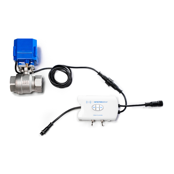
What is Included
There are three pieces of equipment involved in a Trident
controller install.
C
Control
B
Actuated Valve
Assembly
can be connected on the side terminals
A
DT-503 Trident
Valve Controller
™
B
DTVS-C25 & DTVS-C40 Valve Control Cable
C
DT-505-X Actuated Valve Assembly in varying sizes
Valve Controller
Valve
Cable
A
STOPflow
Valve Controller
Sensing cable (optional, not shown) —
of the valve controller.
Equipment Details
valve
Valve Controller
™
Requires standard 110v power. The power adapter (5' length)
is connected to the tail that comes out of the left side of the
valve controller.
• 2 CRV123 backup batteries are pre-installed. Battery tab
needs to be pulled during installation.
Up to two valve connections can be made to a single valve con-
troller using the two tails on the right side of the valve controller.
As the Trident™ system is cloud based, any valve registered on
the system can be closed based on any trigger event.
• The top tail is referred to as connection 1, slot 1 or valve 1.
The bottom tail is connection 2, slot 2, or valve 2.
Valve Control Cable
A valve control cable is needed if the valve controller and
™
actuated valve assembly are installed >5' apart.
• Valve control cables are available in 25' and 40' lengths and
can be connected up to 120'.
Actuated Valve Assembly
Must be installed prior to Valve Controller installation.
Actuators for valves >1.25" have an indicator knob and a brass
clutch.
• Once installed verify the brass plunger/clutch is fully pulled out
and engaged. You should not be able to rotate the valve with
the knob.
Should be installed in an accessible location.
If you are installing a TDG valve near an existing valve, in most
cases it is preferred to locate the TDG valve in line after the cur-
rent valve.
Advertisement

Related Manuals for Watts The Detection Group Trident DT-503


![Controller Watts AERCO Edge [ii] Operation Manual](https://static-data2.manualslib.com/product-images/da1/2085997/60x60/watts-aerco-edge-ii-controller.jpg)


Summary of Contents for Watts The Detection Group Trident DT-503
- Page 1 Installation, Operation and Maintenance Manual Trident Valve Controller ™ Installation Guide WAR N I NG Read this manual BEFORE using this equipment. Failure to read and follow all safety and use information can result in death, serious personal injury, property damage, or damage to the equipment.
- Page 2 Valve Controller Installation and For applications where separate lines provide hot and cold water, 2 valves will be required. Up to 2 valves can be operated by a Registration Process single Valve Controller. Both valves will be closed independently. Valves may be installed in either direction. (For Trident™...
- Page 3 Water Alarm Mode Controlling Valves Device blinks red and beeps once every 3 seconds. Open All Connected Valves: Silence Alarm Press Left Button • Press the Center Button the device will silence and then go Yellow • In Process: LED Solid into a lockout period in which the device will not sense water.
- Page 4 Troubleshooting Components of the System Trident Valve Valve Valve Controller Actuator Connected to the Sends commands Receives commands pipe and physically to the actuator to from the Valve controls the water open or close the Controller and when driven by the valve drives the valve actuator...
Need help?
Do you have a question about the The Detection Group Trident DT-503 and is the answer not in the manual?
Questions and answers