Table of Contents
Advertisement
Quick Links
GF-126
OMM-0051_0D
Used in:
USER MANUAL
• Benchmark Series Boilers
• KC Series Boilers
Installation, Operation, and Maintenance
Boiler Valve Controller
Applicable to:
• 120VAC Models
(BVC)
(Serial# 12-840-1 and above)
• All 24VAC Models
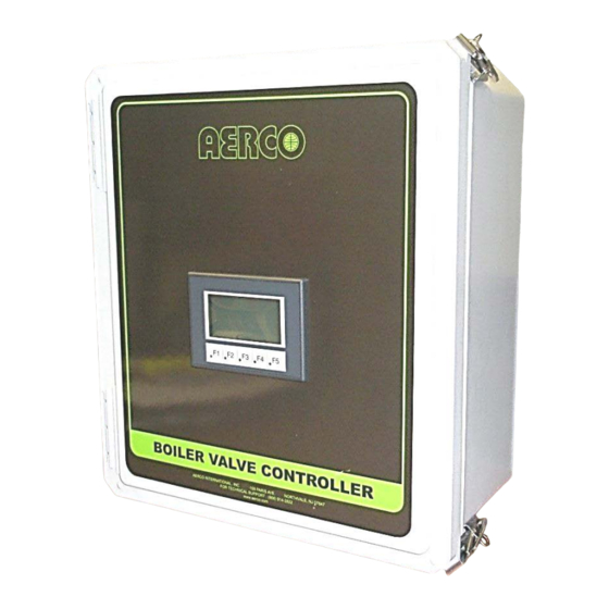
Boiler Valve Controller Front Panel
Revised: 01/20/2013
AERCO International, Inc. • 100 Oritani Dr. • Blauvelt, New York 10913 • Phone: 800-526-0288
Advertisement
Table of Contents

Related Manuals for Watts Aerco 64064
![Controller Watts AERCO Edge [ii] Operation Manual](https://static-data2.manualslib.com/product-images/da1/2085997/60x60/watts-aerco-edge-ii-controller.jpg)


Summary of Contents for Watts Aerco 64064
- Page 1 GF-126 OMM-0051_0D Used in: USER MANUAL • Benchmark Series Boilers • KC Series Boilers Installation, Operation, and Maintenance Boiler Valve Controller Applicable to: • 120VAC Models (BVC) (Serial# 12-840-1 and above) • All 24VAC Models Boiler Valve Controller Front Panel Revised: 01/20/2013 AERCO International, Inc.
- Page 2 GF-126 Boiler Valve Controller User Manual OMM-0051_0D Technical Support: (Mon–Fri, 8am-5pm EST) 1-800-526-0288 www.aerco.com Disclaimer The information contained in this manual is subject to change without notice from AERCO International, Inc. AERCO makes no warranty of any kind with respect to this material, including but not limited to implied warranties of merchantability and fitness for a particular application.
-
Page 3: Table Of Contents
GF-126 Boiler Valve Controller User Manual OMM-0051_0D TABLE OF CONTENTS TABLE OF CONTENTS....................3 1. FOREWARD....................... 4 2. SAFETY PRECAUTIONS ................... 5 3. GENERAL INFORMATION ..................6 3.1 INTRODUCTION ........................6 3.2 MOTOR OPERATED VALVE SPECIFICATIONS ............... 6 3.3 BOILER VALVE CONTROLLER GENERAL DESCRIPTIONS ............6 3.4 USE OF THE BOILER VALVE CONTROLLER ................ -
Page 4: Foreward
GF-126 Boiler Valve Controller (BVC) User Manual OMM-0051_0D 1. FOREWARD The AERCO Boiler Valve Controller (BVC) is designed for variable flow heating systems. The BVC can be configured to control each motor operated valve (MOV) independently to minimize the system flow requirements in a multiple boiler plant. Using the BVC in your system design will save energy, help eliminate over-temperature faults and improve the life and reliability of your AERCO Boilers. -
Page 5: Safety Precautions
GF-126 Boiler Valve Controller (BVC) User Manual OMM-0051_0D 2. SAFETY PRECAUTIONS WARNING 120 VOLTS AC IS USED IN THIS EQUIPMENT. DEATH ON CONTACT OR SERIOUS PERSONAL INJURY MAY RESULT IF EXPOSED CONNECTIONS ARE TOUCHED. THEREFORE, EXERCISE EXTREME CARE WHEN CONNECTING POWER WIRING TO THE UNIT. -
Page 6: General Information
GF-126 Boiler Valve Controller (BVC) User Manual OMM-0051_0D 3. GENERAL INFORMATION 3.1 INTRODUCTION This User’s Manual provides the installation and operation procedures for the AERCO Boiler Valve Controllers (BVCs). Currently, the Boiler Valve Controllers are available in six different models with capabilities as described in the table below. These Boiler Valve Controllers permit AERCO Benchmark and KC1000 Boilers to be used in variable flow systems, while eliminating the need for a dedicated bypass line. -
Page 7: Use Of The Boiler Valve Controller
GF-126 Boiler Valve Controller (BVC) User Manual OMM-0051_0D Figure 1: The AERCO Boiler Valve Controller Box 3.4 USE OF THE BOILER VALVE CONTROLLER There are two basic purposes of the BVCs. They are as follows. 1) Reduce the required minimum system water flow to minimal single boiler flow. 2) Eliminate the need for a boiler bypass flow path by being able to open up flow through the boilers when system demand is satisfied, thereby preventing system pump dead head conditions. -
Page 8: Important Notes
GF-126 Boiler Valve Controller (BVC) User Manual OMM-0051_0D NOTE An operator cannot manually close a boiler valve using the BVC if that particular boiler is firing. IMPORTANT NOTES The following should be noted before reading the remainder of this manual. •... -
Page 9: B I Nstallation
GF-126 Boiler Valve Controller (BVC) User Manual OMM-0051_0D I NSTALLATION I NTRODUCTION This section provides the descriptions and procedures necessary to mount the Boiler Valve Controller and connect them to all boiler plant units and related MOVs. Refer to the appropriate wiring diagrams provided in Figure 8 when making all wiring connections between the Boiler Valve Controller, AERCO boilers, and their associated MOVs. -
Page 10: Drilling Access Holes For Conduit And Cable Connections
GF-126 Boiler Valve Controller (BVC) User Manual OMM-0051_0D Figure 2 - Mounting Foot Kit Figure 3 - Attached Mounting Foot 3. After all four feet are attached, position the Boiler Valve Controller on the wall-mounted plywood sheet or other suitable surface. For easy viewing, position the BVC so that the LCD display is at eye level. -
Page 11: Wiring Requirements
GF-126 Boiler Valve Controller (BVC) User Manual OMM-0051_0D 4.3.3.2 Cover Replacement Assemble hinge pins to the cover by inserting the round end of the pin into the hinge core in the cover. You may need a hammer to gently tap the hinge pin in place. Repeat this step for the second hinge pin. - Page 12 GF-126 Boiler Valve Controller (BVC) User Manual OMM-0051_0D I/O Box Figure 1 - Benchmark Boiler I/O Box Location I/O Box Figure 5 - KC Boiler I/O Box Location AERCO International, Inc. • 100 Oritani Dr. • Blauvelt, New York 10913 • Phone: 800-526-0288 AERCO International, Inc.
- Page 13 GF-126 Boiler Valve Controller (BVC) User Manual OMM-0051_0D Figure 6 – Diagram of Benchmark or KC Boiler I/O Box PCB with Terminal Strips Figure 7 – Photo of Benchmark or KC Boiler I/O Box PCB with Terminal Strips VD2: 01/20/13 AERCO International, Inc.
-
Page 14: C Onnecting The Required Electrical Components (4 Boiler Version)
GF-126 Boiler Valve Controller (BVC) User Manual OMM-0051_0D NOTE The I/O Terminal Strips for the KC and Benchmark Boiler series are identical. 4.4.3 C onnecting the Required Electrical Components (4 Boiler Version) 2 2 B 1. Refer to Figure 6 illustrating the Boiler I/O Box and locate the Auxiliary (AUX) Relay terminals on the lower right terminal strip. -
Page 15: C Onnecting The Required Electrical Components (12 Boiler Version)
GF-126 Boiler Valve Controller (BVC) User Manual OMM-0051_0D 4.4.4 C onnecting the Required Electrical Components (12 Boiler Version) 2 3 B 1. Refer to Figure 6 illustrating the Boiler I/O Box and locate the Auxiliary (AUX) Relay terminals on the lower right terminal strip. 2. - Page 16 GF-126 Boiler Valve Controller (BVC) User Manual OMM-0051_0D Figure 8 - BVC Terminal Block Connection Points (4 Boiler System). Model shown is 64097 (24VAC); for models 64064 & 64095 (120VAC), the MOV Hot Terminals are labeled 120V instead of 24V. Figure 9 - BVC Terminal Block Connection Points (12 Boiler System).
- Page 17 GF-126 Boiler Valve Controller (BVC) User Manual OMM-0051_0D Table 5: Wiring Diagram Selection Guide for AERCO Boiler Valve Controller and AERCO Supplied Belimo Valves How to use the chart below: 1. From the second column, identify the AERCO part number of the Belimo valve being used. 2.
- Page 18 GF-126 Boiler Valve Controller (BVC) User Manual OMM-0051_0D AERCO International, Inc. • 100 Oritani Dr. • Blauvelt, New York 10913 • Phone: 800-526-0288 AERCO International, Inc. • 100 Oritani Dr. • Blauvelt, New York 10913 • Phone: 800-526-0288 VD2: 01/20/13 Page 18 of 38...
- Page 19 GF-126 Boiler Valve Controller (BVC) User Manual OMM-0051_0D VD2: 01/20/13 AERCO International, Inc. • 100 Oritani Dr. • Blauvelt, New York 10913 • Phone: 800-526-0288 Page 19 of 38...
- Page 20 GF-126 Boiler Valve Controller (BVC) User Manual OMM-0051_0D AERCO International, Inc. • 100 Oritani Dr. • Blauvelt, New York 10913 • Phone: 800-526-0288 AERCO International, Inc. • 100 Oritani Dr. • Blauvelt, New York 10913 • Phone: 800-526-0288 VD2: 01/20/13 Page 20 of 38...
- Page 21 GF-126 Boiler Valve Controller (BVC) User Manual OMM-0051_0D VD2: 01/20/13 AERCO International, Inc. • 100 Oritani Dr. • Blauvelt, New York 10913 • Phone: 800-526-0288 Page 21 of 38...
- Page 22 GF-126 Boiler Valve Controller (BVC) User Manual OMM-0051_0D AERCO International, Inc. • 100 Oritani Dr. • Blauvelt, New York 10913 • Phone: 800-526-0288 AERCO International, Inc. • 100 Oritani Dr. • Blauvelt, New York 10913 • Phone: 800-526-0288 VD2: 01/20/13 Page 22 of 38...
- Page 23 GF-126 Boiler Valve Controller (BVC) User Manual OMM-0051_0D VD2: 01/20/13 AERCO International, Inc. • 100 Oritani Dr. • Blauvelt, New York 10913 • Phone: 800-526-0288 Page 23 of 38...
- Page 24 GF-126 Boiler Valve Controller (BVC) User Manual OMM-0051_0D AERCO International, Inc. • 100 Oritani Dr. • Blauvelt, New York 10913 • Phone: 800-526-0288 AERCO International, Inc. • 100 Oritani Dr. • Blauvelt, New York 10913 • Phone: 800-526-0288 VD2: 01/20/13 Page 24 of 38...
- Page 25 GF-126 Boiler Valve Controller (BVC) User Manual OMM-0051_0D VD2: 01/20/13 AERCO International, Inc. • 100 Oritani Dr. • Blauvelt, New York 10913 • Phone: 800-526-0288 Page 25 of 38...
- Page 26 GF-126 Boiler Valve Controller (BVC) User Manual OMM-0051_0D AERCO International, Inc. • 100 Oritani Dr. • Blauvelt, New York 10913 • Phone: 800-526-0288 AERCO International, Inc. • 100 Oritani Dr. • Blauvelt, New York 10913 • Phone: 800-526-0288 VD2: 01/20/13 Page 26 of 38...
- Page 27 GF-126 Boiler Valve Controller (BVC) User Manual OMM-0051_0D VD2: 01/20/13 AERCO International, Inc. • 100 Oritani Dr. • Blauvelt, New York 10913 • Phone: 800-526-0288 Page 27 of 38...
-
Page 28: Fuses And On/Off Switch
GF-126 Boiler Valve Controller (BVC) User Manual OMM-0051_0D 4.4.5 Fuses and On/Off Switch The AERCO Boiler Valve controller uses two standard Buss cylindrical fuses (see Section 4), each rated at 2 Amperes. These fuses are found at the extreme right of the upper electronics module set. -
Page 29: B O Peration
GF-126 Boiler Valve Controller (BVC) User Manual OMM-0051_0D O PERATION I NTRODUCTION 1 2 B The BVC automatically controls each boiler’s Motor Operated Valve (MOV) based on an input from the corresponding boiler. All MOVs will open automatically whenever all boilers are shut down. -
Page 30: The Touch Screen Navigation Logic Sequence
GF-126 Boiler Valve Controller (BVC) User Manual OMM-0051_0D 5.3 THE TOUCH SCREEN NAVIGATION LOGIC SEQUENCE The AERCO Boiler Valve Controller is operated by making use of the front panel touch screen. See Figure 1. As previously mentioned, It should be noted that the five buttons labeled F1 through F5 appearing below the touch screen are for future use only and are not currently operational. - Page 31 GF-126 Boiler Valve Controller (BVC) User Manual OMM-0051_0D Figure 12 - Valve Control Screen Logic Sequence (4 Boiler System) VD2: 01/20/13 AERCO International, Inc. • 100 Oritani Dr. • Blauvelt, New York 10913 • Phone: 800-526-0288 Page 31 of 38...
-
Page 32: 5 B M Anual Valve Control Scenarios
GF-126 Boiler Valve Controller (BVC) User Manual OMM-0051_0D M ANUAL VALVE CONTROL SCENARIOS 1 5 B Two common scenarios are presented in the Scenario 1 and Scenario 2 subsections that follow. NOTE The MOV of a firing boiler cannot be manually overridden to the “CLOSED”... -
Page 33: Scenario 2
GF-126 Boiler Valve Controller (BVC) User Manual OMM-0051_0D Screen 1 Screen 2 Screen 3 Screen 4 Can’t close while Press to open boiler is firing Figure 13 - Valve Control Scenario 1 5.4.2 Scenario 2 In this scenario depicted in Figure 14, none of the boilers are firing and all of the valves are open. - Page 34 GF-126 Boiler Valve Controller (BVC) User Manual OMM-0051_0D On the “VALVES 1-2” screen (Screen 3) the user finds that the MOVs corresponding to the two boilers (Boiler # 1 and Boiler # 2) are already in the “OPEN” position. Since none of the boilers are firing, the user may close a boiler MOV by pressing that particular boiler’s “CLOSE”...
-
Page 35: Sequence For Setting Time Delays
GF-126 Boiler Valve Controller (BVC) User Manual OMM-0051_0D 5.5 SEQUENCE FOR SETTING TIME DELAYS The Main screen also has a “TIMER” touch screen button which is used to set valve closure time delays from one through thirty minutes in one minute intervals. Setting a time delay on a BVC’s valve closure action allows water to continue to flow through a boiler’s heat exchanger even after the boiler stops firing in order to dissipate the residual heat before closing the valve. - Page 36 GF-126 Boiler Valve Controller (BVC) User Manual OMM-0051_0D Figure 16 - Delay Timer Setting Screen Pressing each of the four touch screen buttons located at the right in the illustration above take actions described as follows. Table 7 - Touch Screen Commands TOUCH SCREEN ACTION BUTTON LABEL...
-
Page 37: Spare Parts
GF-126 Boiler Valve Controller (BVC) User Manual OMM-0051_0D 6. SPARE PARTS User replaceable spare parts are listing in the table below. Table 8 - Spare Parts Part Description Two Buss 250 Volt – 2 Ampere ABC-2 fuses are required for the BVC, Fast Acting. - Page 38 GF-126 Boiler Valve Controller (BVC) User Manual OMM-0051_0D © AERCO International, Inc., 2013 AERCO International, Inc. • 100 Oritani Dr. • Blauvelt, New York 10913 • Phone: 800-526-0288 AERCO International, Inc. • 100 Oritani Dr. • Blauvelt, New York 10913 • Phone: 800-526-0288 VD2: 01/20/13 Page 38 of 38...
Need help?
Do you have a question about the Aerco 64064 and is the answer not in the manual?
Questions and answers