Watts AERCO MLX EXT 450 2S Installation, Operation & Maintenance Manual
Hide thumbs
Also See for AERCO MLX EXT 450 2S:
- Technical application manual (37 pages) ,
- Installation, operation & maintenance manual (83 pages)
Table of Contents
Advertisement
Quick Links
Installation, Operation & Maintenance Manual
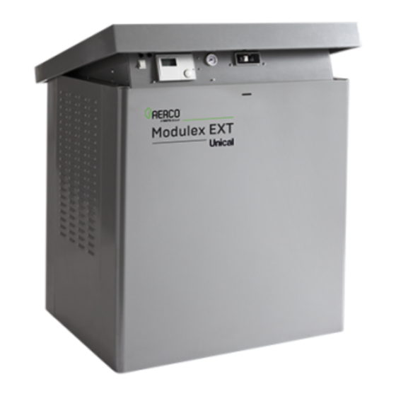
Modulex EXT - Ufly Controller
Light Commercial Series
Modulating and Condensing Boilers
Applies To Modulex Models:
• MLX EXT 450 2S
• MLX EXT 600 2S
• MLX EXT 800 2S
• MLX EXT 1100 2S
Disclaimer
The information contained in this manual is subject to change without notice
from AERCO International, Inc. AERCO makes no warranty of any kind with
respect to this material, including, but not limited to, implied warranties of
merchantability and fitness for a particular application. AERCO International is
not liable for errors appearing in this manual, not for incidental or
consequential damages occurring in connection with the furnishing,
performance, or use of these materials.
• 6/28/2022
OMM-0158_A
Heating and Hot Water Solutions
AERCO International, Inc. • 100 Oritani Drive • Blauvelt, NY 10913
USA: T: (845) 580-8000 • Toll Free: (800) 526-0288 • AERCO.com
Technical Support • (800) 526-0288 • Mon-Fri, 8 am - 5 pm EST
© 2022 AERCO
Advertisement
Table of Contents

Related Manuals for Watts AERCO MLX EXT 450 2S


![Controller Watts AERCO Edge [ii] Operation Manual](https://static-data2.manualslib.com/product-images/da1/2085997/60x60/watts-aerco-edge-ii-controller.jpg)


Summary of Contents for Watts AERCO MLX EXT 450 2S
- Page 1 Installation, Operation & Maintenance Manual Modulex EXT - Ufly Controller Light Commercial Series Modulating and Condensing Boilers Applies To Modulex Models: • MLX EXT 450 2S • MLX EXT 600 2S • MLX EXT 800 2S • MLX EXT 1100 2S Disclaimer The information contained in this manual is subject to change without notice from AERCO International, Inc.
-
Page 2: Table Of Contents
Modulex Light Commercial Series TABLE OF CONTENTS TABLE OF CONTENTS TABLE OF CONTENTS __________________________________________________________________________ 2 CHAPTER 1: SAFETY PRECAUTIONS ______________________________________________________________ 5 CHAPTER 2: GENERAL INFORMATION ____________________________________________________________ 7 2.1 Correct Use Of The Appliance _______________________________________________________________ 7 2.2 Water Treatment ________________________________________________________________________ 7 2.3 Information To Be Made Available To The User _________________________________________________ 7 2.4 Safety Warnings _________________________________________________________________________ 8 2.5 Modifications To Parts Connected To The Appliance _____________________________________________ 8... - Page 3 Modulex Light Commercial Series TABLE OF CONTENTS 4.11 Propane Gas Connections ________________________________________________________________ 34 4.12 Flow And Return Pipe Connections ________________________________________________________ 35 4.13 Pressure Relief Valve (Supplied) ___________________________________________________________ 35 4.14 Csd-1 Manifold Assembly (Supplied) _______________________________________________________ 35 Installing the Flow Switch and CSD-1 Components _________________________________________ 36 4.15 Determination Of Primary Boiler Pump Or Boiler System Pump __________________________________ 37 4.16 Condensate Piping And Drain _____________________________________________________________ 38 4.17 Water Treatment ______________________________________________________________________ 39...
- Page 4 Modulex Light Commercial Series TABLE OF CONTENTS Ufly Controller Features and Functions ___________________________________________________ 71 Reading the Icons on Home Page _______________________________________________________ 72 Display Modes ______________________________________________________________________ 73 5.2 Bcm (Boiler Communication Module) _______________________________________________________ 73 CHAPTER 6: OPERATION, MENU & PARAMETERS __________________________________________________ 75 6.1 Setup Menu ___________________________________________________________________________ 76 Setting Time and Date ________________________________________________________________ 76 Setting Comfort and Eco Building Reference Temperatures ___________________________________ 76...
-
Page 5: Chapter 1: Safety Precautions
Modulex Light Commercial Series SAFETY PRECAUTIONS CHAPTER 1: SAFETY PRECAUTIONS Observe all CAUTIONS and WARNINGS in this manual to avoid injury, death, and damage to the equipment. Failure to heed safety warnings and cautions may void applicable warranties. W A R N I N G ! Never use flames to detect gas leaks! What to do if you smell gas: •... - Page 6 Modulex Light Commercial Series SAFETY PRECAUTIONS a) In the event that the side wall horizontally vented gas fueled equipment is installed in a crawl space or an attic, the hard-wired carbon monoxide detector with alarm and battery back-up may be installed on the next adjacent floor level. b) In the event that the requirements of this subdivision cannot be met at the time of completion of installation, the owner shall have a period of thirty (30) days to comply with the above requirements;...
-
Page 7: Chapter 2: General Information
Modulex Light Commercial Series CHAPTER 2: General Information CHAPTER 2: GENERAL INFORMATION 2.1 Correct Use Of The Appliance The MODULEX EXT boiler has been designed utilizing the latest heating technologies and in compliance with the current safety regulations. However, if not used or operated properly, the unit may cause injury or death to persons, or serious damage to the equipment or surrounding objects. -
Page 8: Safety Warnings
Modulex Light Commercial Series CHAPTER 2: General Information 2.4 Safety Warnings W A R N I N G ! • Children must be supervised so they do not play on, around, or with the appliance. • The installation, adjustment, and servicing of this appliance must be carried out by a competent person and installed in accordance with the current standards and regulations. -
Page 9: Data Plate
Modulex Light Commercial Series CHAPTER 2: General Information 2.7 Data Plate Each unit is fitted with a data plate indicating gas type, power source and venting classification. A sample Data Plate for a MODULEX EXT boiler is shown in the left figure below. A sample of the Data Packaging label is shown in the right image below. -
Page 10: Operational Requirements
Modulex Light Commercial Series CHAPTER 2: General Information 2.8 Operational Requirements General Requirements The following instructions MUST be followed: • Boiler must only be used for its designated purpose as described. • Each unit is fitted with a data plate. Consult the details on this plate to verify whether the boiler is compliant with its intended location, e.g.: gas type, power source and venting classification. -
Page 11: Tools, Materials, And Additional Equipment
Modulex Light Commercial Series CHAPTER 2: General Information • Close the valves of the boiler while flushing the system, do not introduce any system cleaner into the boiler loop. Flush system thoroughly to remove all system cleaner before filling boiler. Approved antifreeze (maximum concentration of 50%): •... -
Page 12: Installation And Servicing Personnel
Modulex Light Commercial Series CHAPTER 2: General Information Installation and Servicing Personnel Installation and servicing must be carried out in accordance with the regulations in force according to the manufacturer’s instructions and by legally competent authorized persons. By definition, a competent person is a person who has a specific technical qualification in the field of components for central heating systems for domestic use, domestic hot water production, and servicing. -
Page 13: Chapter 3: Technical Features & Dimensions
Modulex Light Commercial Series CHAPTER 3: TECHNICAL FEATURES & DIMENSIONS CHAPTER 3: TECHNICAL FEATURES & DIMENSIONS 3.1 Modulex Ext Technical Features • Compact, gas fired, Low NO , condensing boiler. • Comprised of one sectional boiler body, suitable as a single boiler or in a cascaded group. •... -
Page 14: General Boiler Operation
Modulex Light Commercial Series CHAPTER 3: TECHNICAL FEATURES & DIMENSIONS • Ufly electronic controller included. • BCM (Boiler Communication Manager) included. • Ability to control power of the individual heating elements. • Control of heat demand: constant or remote setpoint. •... -
Page 15: Dimensional Drawings
Modulex Light Commercial Series CHAPTER 3: TECHNICAL FEATURES & DIMENSIONS 3.4 Dimensional Drawings On Modulex EXT models 321, 642 and 962 the flue terminal ends inside the casing Figure 3-1: MODULEX EXT Dimensional Drawings (Side Views) OMM-0158_A • 6/28/2022 Technical Support • (800) 526-0288 • Mon-Fri, 8 am - 5 pm EST Page 15 of 120... - Page 16 Modulex Light Commercial Series CHAPTER 3: TECHNICAL FEATURES & DIMENSIONS Figure 3-2: MODULEX EXT and Vent Adaptor Dimensional Drawings (Top View) TABLE 3-1: MODULEX EXT Dimensions and Sizes Model 450 2S 600 2S 800 2S 1100 2S Dimensions No. of Modules Height (Open) - 52.1‘‘...
- Page 17 Modulex Light Commercial Series CHAPTER 3: TECHNICAL FEATURES & DIMENSIONS CONTROL PANEL Figure 3-3: MODULEX EXT Main Components (Left Side View) OMM-0158_A • 6/28/2022 Technical Support • (800) 526-0288 • Mon-Fri, 8 am - 5 pm EST Page 17 of 120...
- Page 18 Modulex Light Commercial Series CHAPTER 3: TECHNICAL FEATURES & DIMENSIONS Figure 3-4: MODULEX EXT Main Components (Right Side View) • Exhaust and condensate evacuation connections are on the RIGHT-HAND side (supply condition), but may be moved to the REAR position. •...
-
Page 19: Performance Data
Modulex Light Commercial Series CHAPTER 3: TECHNICAL FEATURES & DIMENSIONS 3.5 Performance Data TABLE 3-2: MODULEX EXT Performance Data EXT 450 2S EXT 600 2S EXT 800 2S EXT 1100 2S Min Input 46,000 46,000 46,000 46,000 Max Input 481,500 642,000 802,500 1,123,500... - Page 20 Modulex Light Commercial Series CHAPTER 3: TECHNICAL FEATURES & DIMENSIONS (This page intentionally blank) OMM-0158_A • 6/28/2022 Technical Support • (800) 526-0288 • Mon-Fri, 8 am - 5 pm EST Page 20 of 120...
-
Page 21: Chapter 4: Installation Instructions
Modulex Light Commercial Series CHAPTER 4: Installation Instructions CHAPTER 4: INSTALLATION INSTRUCTIONS 4.1 General Warnings Appropriate Use of the Boiler This boiler MUST be used for the use for which it has been expressively designed. Any other use shall be considered improper and therefore dangerous. This boiler is designed to heat water at a temperature below the boiling point at atmospheric pressure. -
Page 22: Code And Standards Approvals
Modulex Light Commercial Series CHAPTER 4: Installation Instructions 4.2 Code And Standards Approvals The MODULEX EXT boiler has been reviewed for compliance with the applicable sections of the following North American Standards: • ANSI Z21.13/CSA 4.9: Gas-fired low pressure steam and hot water boilers •... - Page 23 Modulex Light Commercial Series CHAPTER 4: Installation Instructions On The Boiler Right Side: • One 39.3 inch (1 meter) pipe for the condensate evacuation system. • Left and right skirt pieces. On The Back Of The Boiler • Front and rear skirt pieces. On The Boiler Top: •...
- Page 24 Modulex Light Commercial Series CHAPTER 4: Installation Instructions Figure 4-2: Unpacking TABLE 4-1: MODULEX EXT Shipping Package Dimensions Model Gross Weight 43.7‘‘ 35.0‘‘ 49.2‘‘ 520 lb. EXT 450 2S 1110 mm 890 mm 1250 mm 236 kg 43.7‘‘ 35.0‘‘ 49.2‘‘ 650 lb.
-
Page 25: Transporting And Securing The Boiler Safely
Modulex Light Commercial Series CHAPTER 4: Installation Instructions 4.4 Transporting And Securing The Boiler Safely The boiler is susceptible to serious damage when not secured properly. • Follow the transportation instructions on the packaging. • Only transport the boiler using appropriate transportation equipment, such as a hand-truck with a fastening belt or special equipment for transporting heavy equipment. - Page 26 Modulex Light Commercial Series CHAPTER 4: Installation Instructions Figure 4-4: EXT Unpacking (Left = Attach Feet, Right = Ready for Cover) 23.82 (605 mm) MLX 450 2S = 26.14 in. (664 mm) MLX 600-800 2S = 36.69 in. (932 mm) MLX 1100 2S = 47.24 in.
-
Page 27: Boiler Location Inside A Boiler Room
Modulex Light Commercial Series CHAPTER 4: Installation Instructions 4.6 Boiler Location Inside A Boiler Room Special attention shall be paid to local regulations and laws about boiler enclosures and boiler rooms, particularly to the minimum clearances around the boiler. The installation shall be in compliance with all the latest regulations and laws about boiler enclosures, boiler rooms, installations of heating and hot-water systems, ventilation, vents capable of exhausting the flue gases of condensing boilers, and any other applicable requirements. -
Page 28: Products To Avoid In The Boiler Room
Modulex Light Commercial Series CHAPTER 4: Installation Instructions Products to Avoid in the Boiler Room Do NOT store the following products in boiler room and/or around combustion air intake vents: • Spray cans containing chlorocarbons/fluorocarbons • Ammonium and/or ammonium solutions •... -
Page 29: Boiler Connections
Modulex Light Commercial Series CHAPTER 4: Installation Instructions 4.8 Boiler Connections At delivery, the MODULEX EXT boiler is setup with all connections, (i.e. cold/hot water flow & return, gas, and exhaust outlet) on its RIGHT HAND side. Changing Exhaust Outlet Location To move the flue exhaust outlet terminal from the RIGHT HAND side (standard delivery position) to the REAR position, it is necessary to request the Rear Exhaust kit, which includes a cover for closing off the RIGHT HAND side panel exhaust opening (see Figure 4-10). -
Page 30: Reversing Gas Manifold Connections
Modulex Light Commercial Series CHAPTER 4: Installation Instructions Exhaust Opening Cover Figure 4-9: Rear Exhaust Kit for Changing Exhaust Outlet from RIGHT HAND Side to REAR Reversing Gas Manifold Connections To move the gas connection from the RIGHT HAND side (standard delivery position) to the LEFT HAND side, swap the end plate and the gas supply connector screwed onto the gas manifold ends, as shown in Figure 4-11. -
Page 31: Reversing Cold/Hot Water Flow & Return Connections
Modulex Light Commercial Series CHAPTER 4: Installation Instructions Reversing Cold/Hot Water Flow & Return Connections Change of Water Flow and Return connections from RIGHT hand to LEFT hand requires reversing connectors, moving the Flow and Return Temperture Sensors to other end, and exchanging positions of the Boiler Sensor KF and Automatic Air Vent. - Page 32 Modulex Light Commercial Series CHAPTER 4: Installation Instructions 4.8.3.2 Reversing Flow & Return Temperature Sensors One sensor is located on top of the lower Return pipe railing, the other is located under the upper Flow pipe railing. Move these two sensors to other end of Flow/Return pipes. C.H.
-
Page 33: Gas Connection General Information
Modulex Light Commercial Series CHAPTER 4: Installation Instructions Figure 4-14: Caps and Plugs Used for Closing Up Vacated Gas and Hydraulic Connection Openings 4.9 Gas Connection General Information For natural gas connections, see section 4.10.1. For propane gas, refer to section 4.10.2. The gas supply connection must comply with local regulations or, if such regulations do not exist, with the National Fuel Gas Code, ANSI Z223.1/NFPA 54. -
Page 34: Natural Gas Connections
Modulex Light Commercial Series CHAPTER 4: Installation Instructions W A R N I N G ! • The gas connection must be installed by a registered engineer who must comply with regulations in force and/or indicated by the local gas supplier. Incorrect installation can cause injury or death to persons or animals, or damage to property. -
Page 35: Flow And Return Pipe Connections
Modulex Light Commercial Series CHAPTER 4: Installation Instructions 4.12 Flow And Return Pipe Connections The cold and hot water flow and return circuits must be connected to the boiler via the respective 2½” M and R connections, as indicated in Table 3-1 (in Section 3.3, above). When determining the size of the cold/hot water circuit pipes, bear in mind the pressure losses induced by any of the system’s components and by the configuration of the system. -
Page 36: Installing The Flow Switch And Csd-1 Components
Modulex Light Commercial Series CHAPTER 4: Installation Instructions NOTE: Use Teflon tape or suitable pipe joint compound for component and piping connections. Installing the Flow Switch and CSD-1 Components 1. Attach manifold to the outlet supply connection on the boiler via the flanged connections. 2. -
Page 37: Determination Of Primary Boiler Pump Or Boiler System Pump
Modulex Light Commercial Series CHAPTER 4: Installation Instructions 4.15 Determination Of Primary Boiler Pump Or Boiler System Pump ∆t The following table gives an indication of the pump’s flow rate in function of the of the primary circuit if the installation has a mixing header. The size of the pumps must be determined by installers or technical engineers according to boiler data and system design. -
Page 38: Condensate Piping And Drain
Modulex Light Commercial Series CHAPTER 4: Installation Instructions 4.16 Condensate Piping And Drain To avoid condensate collecting inside the combustion exhaust system, the condenate piping must have an inclination toward the drain of at least 3/8 in./ft (30 mm/m). The liquid column, inside the condensate siphon, (see Condensate Siphon Plug in Figure 4-18) needs to be filled with water after installation. -
Page 39: Water Treatment
Modulex Light Commercial Series CHAPTER 4: Installation Instructions W A R N I N G ! • Before commissioning the boiler, fill the condensate drain pipe with water, at the dedicated filling-up plug. See Figure 4-18. • Do not install the condensate drain where freezing may occur. •... -
Page 40: Important Installation Warnings
Modulex Light Commercial Series CHAPTER 4: Installation Instructions 4.18 Important Installation Warnings Oxygen Levels in the System Water Warning All necessary precautions must be taken for preventing the formation and localization of oxygen in the system’s water. For this reason, ensure that the plastic piping used in under-floor heating systems is impermeable to oxygen. -
Page 41: Flue Manifold Connection
Modulex Light Commercial Series CHAPTER 4: Installation Instructions 4.20 Flue Manifold Connection To assemble the flue manifold to the boiler flue exhaust opening, retrieve the six (6) nuts and washers from the plastic bag, shipped with the boiler, and affix to the boiler opening per Figure 4- 22. -
Page 42: Flue Exhaust Piping To Vent
Modulex Light Commercial Series CHAPTER 4: Installation Instructions 4.21 Flue Exhaust Piping To Vent In a condensing boiler, the flue exhaust is evacuated at a very low temperature (maximum of about 183°F - 84°C). Thus, it is necessary that the chimney be impermeble to the condensate of the combustion products and is made of corrosion resistant materials. -
Page 43: Vent Starter Pieces
Modulex Light Commercial Series CHAPTER 4: Installation Instructions 4.22 Vent Starter Pieces The table below lists the vent starter pieces. PVC starter pieces are included with every unit. For stainless steel and polypropylene vent starter pieces, see the table below for availability and sourcing information. -
Page 44: Combustion Air And Ventilation Openings
Modulex Light Commercial Series CHAPTER 4: Installation Instructions The flue venting pipe is affixed to the adapter using high temperature RTV and then clamped with a worm-driven Hose Clamp. When using non-metallic (plastic) venting materials, use Schedule 40 or thicker Single-wall, uninsulated pipes. -
Page 45: Room Air Combustion
Modulex Light Commercial Series CHAPTER 4: Installation Instructions W A R N I N G ! Fire danger due to flammable materials or liquids. Do not store flammable materials and liquids in the immediate vicinity of the boiler. See Section 4.6.2 for warnings and guidelines concerning materials and contaminents that should be avoided in the boiler room and near air inlets when operating the boiler. -
Page 46: Important Factors For Terminal Orientation And Location
Modulex Light Commercial Series CHAPTER 4: Installation Instructions It is not recommended to terminate vent above any door or window, as condensate can freeze causing ice formations. Do not use a chimney as a raceway if another boiler or fireplace is vented into or through the chimney. -
Page 47: Vent Pipe Sizing
Modulex Light Commercial Series CHAPTER 4: Installation Instructions 4.25 Vent Pipe Sizing The maximum length is the combined length of straight horizontal and vertical runs, and the equivalent straight length of fittings. The required lengths for each boiler are as follows: NOTE: The examples referenced in the table below are on the next page. - Page 48 Modulex Light Commercial Series CHAPTER 4: Installation Instructions Figure 4-26: Modulex EXT Allowable Venting Solutions OMM-0158_A • 6/28/2022 Technical Support • (800) 526-0288 • Mon-Fri, 8 am - 5 pm EST Page 48 of 120...
-
Page 49: Electrical Connections
Modulex Light Commercial Series CHAPTER 4: Installation Instructions 4.26 Electrical Connections Regulations in Force The electrical connections to the boiler must be made in accordance with all applicable local codes and the latest revision of the National Electrical Code, ANSI/NFPA-70. Installations in Canada should also conform with CSA C22.1 Canadian Electrical Code Part 1. -
Page 50: Service Relay Requirement
Modulex Light Commercial Series CHAPTER 4: Installation Instructions Service Relay Requirement Upstream of the electrical connection, a service relay is required (not supplied) which, when the additional electrical safety devices (if any) intervene, shuts down the electrical supply to the on- off fuel valve fitted on the gas supply circuit, but not to the boiler so as to guarantee the running of the pump and permit the boiler to cool down Electrical Requirements... - Page 51 Modulex Light Commercial Series CHAPTER 4: Installation Instructions NOTE: Use the following disconnect switch and circuit breaker size: • Models MLX EXT 450 2S - 1100 2S: 15 AMP • Models MLX EXT 1500 2S - 3000 2S: 30 AMP Figure 4-28: Main Power Junction Box Location and 120VAC Wiring OMM-0158_A •...
-
Page 52: Functional Wiring Diagram Page 1
Modulex Light Commercial Series CHAPTER 4: Installation Instructions 4.27 FUNCTIONAL WIRING DIAGRAM Page 1 OMM-0158_A • 6/28/2022 Technical Support • (800) 526-0288 • Mon-Fri, 8 am - 5 pm EST Page 52 of 120... -
Page 53: Functional Wiring Diagram Page 2
Modulex Light Commercial Series CHAPTER 4: Installation Instructions 4.28 FUNCTIONAL WIRING DIAGRAM Page 2 OMM-0158_A • 6/28/2022 Technical Support • (800) 526-0288 • Mon-Fri, 8 am - 5 pm EST Page 53 of 120... -
Page 54: Ladder Diagrams
Modulex Light Commercial Series CHAPTER 4: Installation Instructions 4.29 Ladder Diagrams Figure 4-29: Module Ladder Diagram OMM-0158_A • 6/28/2022 Technical Support • (800) 526-0288 • Mon-Fri, 8 am - 5 pm EST Page 54 of 120... -
Page 55: General Ladder Diagram
Modulex Light Commercial Series CHAPTER 4: Installation Instructions 4.30 General Ladder Diagram Figure 4-30: General Ladder Diagram OMM-0158_A • 6/28/2022 Technical Support • (800) 526-0288 • Mon-Fri, 8 am - 5 pm EST Page 55 of 120... -
Page 56: Input/Output Box Terminal Assignments
Modulex Light Commercial Series CHAPTER 4: Installation Instructions 4.31 Input/Output Box Terminal Assignments Heating system components such as pump, outside air sensor and flow switch must be connected to the Input/Output box. Alarm contact, analog control input (0--10V) and Modbus communication are also connected to the Input/Output box. -
Page 57: Starting Up: Filling And De-Aerating The Boiler
Modulex Light Commercial Series CHAPTER 4: Installation Instructions Figure 4-32: Sensor and BCM Terminal Assignments 4.32 Starting Up: Filling And De-Aerating The Boiler Carry out the following tasks in connection with maintenance, etc. to an already installed unit: • Shut down all programs •... -
Page 58: Filling The System
Modulex Light Commercial Series CHAPTER 4: Installation Instructions 4.33 Filling The System Necessary Precautions While Filling the System Do not mix the C/H system’s water with anti-freeze or anti-corrosion solutions using incorrect concentrations! Doing so can cause damage to the gaskets and might cause noise during normal boiler operation. - Page 59 Modulex Light Commercial Series CHAPTER 4: Installation Instructions FOR YOUR SAFETY READ BEFORE OPERATING WARNING: If you do not follow these instructions, a fire or explosion may result causing property damage, personal injury, or loss of life. A. This appliance does not have a pilot light. It is equipped with an ignition device, which automatically lights the burner.
-
Page 60: Testing The Ignition Safety Shut Off Device
Modulex Light Commercial Series CHAPTER 4: Installation Instructions 4.34 Testing The Ignition Safety Shut Off Device 1. Power on by switching on the ON-OFF switch. 2. Create a request in C/H Central Heating. 3. Turn burners ON. 4. Disconnect the plug and socket connection of the ionization cable (WHITE) of BURNER 1. 5. -
Page 61: Burner Calibration
Modulex Light Commercial Series CHAPTER 4: Installation Instructions 4.35 Burner Calibration W A R N I N G ! These instructions are for qualified AERCO service technicians or installers only. All boilers come pre-calibrated and tested. However, if it is necessary to change the calibration due to gas conversion or adaptation to the main supply system, the gas valve must be re- calibrated (using Service Mode in the Burner Menu of the Ufly Controller, see section 6.5). -
Page 62: Maximum Output Calibration
Modulex Light Commercial Series CHAPTER 4: Installation Instructions Maximum Output Adjust Minimum Output Adjust Figure 4-34: Location of Minimum and Maximum Adjustments (Top View) Maximum Output Calibration After installing the gas analyzer probe (Figure 4-33), refer to Figure 4-38 to locate the gas valves and the Maximum Gas Adjustment screw (A) on each valve. -
Page 63: Minimum Output Calibration
Modulex Light Commercial Series CHAPTER 4: Installation Instructions Minimum Output Calibration After setting the maximum gas output for each valve (section 4.34.2), refer to Figure 4-38, above, to locate the Minimum Gas Adjustment screw (B) on each valve. Follow the instructions below to set the minimum gas output level for each valve. - Page 64 Modulex Light Commercial Series CHAPTER 4: Installation Instructions TABLE 4-6: Modulex EXT Pressure, CO and O Level Calibration Tables EXT 450 2S Gas Consumption Supply Level (%) O Level (%) Fan Speed Ǿ Mixer /hr (m /hr) Start V max Gas Type Pressure Injectors Ǿ...
-
Page 65: Sweeper Mode (Manual Control)
Modulex Light Commercial Series CHAPTER 4: Installation Instructions 4.36 Sweeper Mode (Manual Control) 1. Insert psw and select sweeper again. Vary % mod. request from 10% to 100%. 2. Activate Sweeper Mode. 3. Chose burner among those available, e.g.: usually 1 / Modulex (from 1 to 8). NOTE: Note: once selected the burner, (3) the display page changes: Burner # 1 .. - Page 66 Modulex Light Commercial Series CHAPTER 4: Installation Instructions 5. Burner operating to maximum power 6. Vary % of modulation request to the (modulation 100%). minimum 10% and select the burner. 7. Boiler operating with modulation min. 8. Disable SWEEPER function. Exit by (modulation 0%).
-
Page 67: High Altitude Adjustment
Modulex Light Commercial Series CHAPTER 4: Installation Instructions 4.37 High Altitude Adjustment It is necessary to adjust the fan speed at altitudes at or above 5,000 feet. Modify parameter 526 (FU: Fan maximum speed) of the BMM (Burner Management Module) in the Devices Menu. NOTE: This is modifiable only with an access code. -
Page 68: High Altitude Conversion Label
Modulex Light Commercial Series CHAPTER 4: Installation Instructions 4.38 High Altitude Conversion Label After calibration of the unit from Normal Altitude (0 - 2,000 feet) to High Altitude (2,000 – 4,500 feet) operation, the label below must be filled out and near the rating label. If the unit is calibrated again for normal altitude operation, the label should be removed. -
Page 69: Controls And Emergency Functions
Modulex Light Commercial Series CHAPTER 4: Installation Instructions 4.40 Controls And Emergency Functions OMM-0158_A • 6/28/2022 Technical Support • (800) 526-0288 • Mon-Fri, 8 am - 5 pm EST Page 69 of 120... -
Page 70: Initial Boiler Ignition
Modulex Light Commercial Series CHAPTER 4: Installation Instructions 4.41 Initial Boiler Ignition Preliminary Checks W A R N I N G ! To ensure the continued safe operation of the boiler it is highly recommended that it is checked at regular intervals and serviced when necessary, and that only original spare parts are used. Regular attention will prolong the life of the boiler. -
Page 71: Chapter 5: Ufly Controller & Bcm Modules
Modulex Light Commercial Series CHAPTER 5: Ufly Controller and BMC Modules CHAPTER 5: UFLY CONTROLLER & BCM MODULES MODULEX boilers contain advanced and reliable electronic controls, the Ufly Controller and the BCM (Boiler Communications Module), which provide comprehensive programming and monitoring of the MODULEX boiler and its functions. -
Page 72: Reading The Icons On Home Page
Modulex Light Commercial Series CHAPTER 5: Ufly Controller and BMC Modules Reading the Icons on Home Page Heating: Access space heating parameters including setpoint, outdoor reset and building reference temperature. Domestic Hot Water: Access domestic hot water parameters including setpoint, timed programming, and legionella protection function Solar: This menu is currently not available. -
Page 73: Display Modes
Modulex Light Commercial Series CHAPTER 5: Ufly Controller and BMC Modules Display Modes 6 Display Mode 7 Display Mode 8 Display Mode Screen Off Home Screen Menu Screen 5.2 Bcm (Boiler Communication Module) The BCM (Boiler Communication Module) is an electronic module in MODULEX boilers, which supports full interoperability to BAS (Building Automation Systems) via Modbus protocol to make remote communications and control possible. - Page 74 Modulex Light Commercial Series CHAPTER 5: Ufly Controller and BMC Modules Figure 5-1: Boiler Communications Module (BCM) Figure 5-2: BCM Key and LEDs Legend OMM-0158_A • 6/28/2022 Technical Support • (800) 526-0288 • Mon-Fri, 8 am - 5 pm EST Page 74 of 120...
-
Page 75: Chapter 6: Operation, Menu & Parameters
Modulex Light Commercial Series SECTION 6: Gas Supply and Piping CHAPTER 6: OPERATION, MENU & PARAMETERS This chapter introduces the Ufly controller basic menu contents needed to set up the MODULEX EXT boiler. For more detailed information concerning the Ufly controller menus, operating modes and functions, refer to the Ufly Controller User Manual (OMM-0159). -
Page 76: Setup Menu
Modulex Light Commercial Series SECTION 6: Gas Supply and Piping 6.1 Setup Menu The Setup Menu allows the user to setup time and date, program Building Reference temperatures and domestic hot water setpoint, change display and language settings, and change the password for the Devices. Setting Time and Date Setting Comfort and Eco Building Reference Temperatures The Comfort and Eco Building Reference Temperatures for the Outdoor Reset Mode are... -
Page 77: Setting Comfort And Eco Domestic Hot Water Setpoints
Modulex Light Commercial Series SECTION 6: Gas Supply and Piping Setting Comfort and Eco Domestic Hot Water Setpoints The Comfort and Eco Domestic Hot Water Setpoints are programmed in the Setup Menu. For details on Domestic Hot Water Operation, see section 4.4 of the Control Manual OMM-0159. The Ufly screen automatically turns off after 20 seconds (default) of inactivity. -
Page 78: Password
Modulex Light Commercial Series SECTION 6: Gas Supply and Piping Password For security and protection of the boiler, the default password is only availalbe to Authorized AERCO Service technicians. To Change the password: 1. Enter the current password and click OK 2. -
Page 79: Domestic Hot Water Menu
Modulex Light Commercial Series SECTION 6: Gas Supply and Piping Outdoor Reset Parameter and Space Heating Setpoint can be accessed by clicking the settings button. Building Reference Temperatures to use in Outdoor Reset Mode can be selected in the Heating Menu. -
Page 80: Devices Menu
Modulex Light Commercial Series SECTION 6: Gas Supply and Piping The DHW Setpoint to use can be selected in the Domestic Hot Water Menu 6.4 Devices Menu The Devices Menu allows access to BMM (Burner Management Module) parameters, BCM parameters for functions including 0-10V operation and domestic hot water operation, and error history. - Page 81 Modulex Light Commercial Series SECTION 6: Gas Supply and Piping Access the BCM Menu by clicking the hcm button. See Section 6.6 for list of BCM Parameters. Access the BMM Menu by clicking the bmm buttons. See Section 6.7 for list of BMM Parameters.
-
Page 82: Burner Menu
Modulex Light Commercial Series SECTION 6: Gas Supply and Piping 6.5 Burner Menu The Burner Menu allows access to calibration, manual operation, and troubleshooting settings. This menu is password protected and is only for authorized AERCO technicians. Service Mode/Manual Firing Rate Function 1. -
Page 83: Manual Setpoint Function
Modulex Light Commercial Series SECTION 6: Gas Supply and Piping 7. If desired, user can select which burner(s) to run during manual firing rate function. a. Select one of the available burners b. Note that the next screen shown is for the selected Burner. c. -
Page 84: Reset Burner Working Hours And Ignition Count
Modulex Light Commercial Series SECTION 6: Gas Supply and Piping Reset Burner Working Hours and Ignition Count Select one of the available burners Click the Reset button. Password will be required to proceed. OMM-0158_A • 6/28/2022 Technical Support • (800) 526-0288 • Mon-Fri, 8 am - 5 pm EST Page 84 of 120... -
Page 85: Bcm Parameters
Modulex Light Commercial Series SECTION 6: Gas Supply and Piping 6.6 Bcm Parameters This section provides the list of the parameters in the BCM. See Section 6.4 for instructions on how to navigate to the BCM parameters. PARAMETER DESCRIPTION ENTRY RANGE DEFAULT Enabled services 16 = Control via Modbus*... - Page 86 Modulex Light Commercial Series SECTION 6: Gas Supply and Piping PARAMETER DESCRIPTION ENTRY RANGE DEFAULT Pump: maximum control 0-10V (Maximum output pump modulation) See Controls Manual OMM-0159 Section 6.4.3 CH Maximum modulation 0-100% 100% CH Parallel: maximum error This is the maximum boiler outlet error that 0°F to 54°F disables the CH and DHW parallel operation.
- Page 87 Modulex Light Commercial Series SECTION 6: Gas Supply and Piping PARAMETER DESCRIPTION ENTRY RANGE DEFAULT 68°F to Param. 39 Burner: Minimum Setpoint 68F (20C) (20°C to Param. 39) Minimum modulation: MLX EXT 450 2S This parameter plays a part (along with -1100 2S: 31% others) in the algorithm that determines 0-100%...
- Page 88 Modulex Light Commercial Series SECTION 6: Gas Supply and Piping PARAMETER DESCRIPTION ENTRY RANGE DEFAULT Programmable Relay#2 (Alarm Relay) Function (BCM connector Y4, terminals 3 and 4) 0 = Contact closes if a failure prevents See Description the insertion of the requested number of burner(s) 1 = Contact closes with each failure of the boiler...
-
Page 89: Bmm Parameters
Modulex Light Commercial Series SECTION 6: Gas Supply and Piping 6.7 Bmm Parameters This section provides the list of the parameters in the BMM (Burner Management Module) boards. See Section 6.4 for instructions on how to navigate to the BMM parameters. PARAMETER DESCRIPTION ENTRY RANGE... - Page 90 Modulex Light Commercial Series SECTION 6: Gas Supply and Piping PARAMETER DESCRIPTION ENTRY RANGE DEFAULT Fan: pulse/revolution 0/1-4 Note: Leave at the default value of 2 Fan regulation: proportional band MLX EXT 450 2S -1100 2S: 10 0-50 MLX EXT 1500 2S -3000 2S: 30 Fan regulation: integral gain 0-50...
- Page 91 Modulex Light Commercial Series SECTION 6: Gas Supply and Piping PARAMETER DESCRIPTION ENTRY RANGE DEFAULT Programmable Sensor #1 function - NOT APPLICABLE. Note: Leave at default value of 1 APS check - NOT APPLICABLE. Note: Leave at default value of 0 Temperature sensors 0: 10K @ 25°C, B=3977 1: 10K @ 25°C, B=3435...
-
Page 92: Chapter 7: Troubleshooting
Modulex Light Commercial Series SECTION 6: Gas Supply and Piping CHAPTER 7: TROUBLESHOOTING 7.1 Ufly Controller Error Codes Fault codes are displayed in the right hand section of the Ufly Controller display (see Figure-7-1). There are codes for the following two different devices: •... -
Page 93: Bcm (Boiler Communications Module) Fault Codes
Modulex Light Commercial Series SECTION 6: Gas Supply and Piping BCM (Boiler Communications Module) Fault Codes The table below lists the fault codes and troubleshooting tips associated with the BCM. FAULT CODE DESCRIPTION EFFECT CORRECTION RESET HCM: 2 Gas Pressure Switch Low gas pressure - NOT APPLICABLE. - Page 94 Modulex Light Commercial Series SECTION 6: Gas Supply and Piping FAULT CODE DESCRIPTION EFFECT CORRECTION RESET Low system flow rate. Water flow is not HCM: 40 detected by sensor Check water flow or Burners turned OFF. AUTOMATIC Low water flowrate connected to BCM check switch.
-
Page 95: Bmm (Burner Management Module) Fault Codes
Modulex Light Commercial Series SECTION 6: Gas Supply and Piping BMM (Burner Management Module) Fault Codes The table below lists the fault codes and troubleshooting tips associated with the BMM. CODE DESCRIPTION EFFECT CORRECTION RESET MANUAL - push reset BMM: 1 High Limit (STB) All burners turned Check flow sensor thermal... - Page 96 Modulex Light Commercial Series SECTION 6: Gas Supply and Piping CODE DESCRIPTION EFFECT CORRECTION RESET If fan is stopped, check supply voltage and fan wiring. If OK, try another fan. If still not working, change the BMM. Ignition retry after 60 Air pressure switch BMM: 22 second delay and...
-
Page 97: Chapter 8: Maintenance Schedule
Modulex Light Commercial Series CHAPTER 9: Spare Parts Drawings and Lists CHAPTER 8: MAINTENANCE SCHEDULE The boiler must receive regular, annual maintenance and cleaning in order to ensure reliable and efficient operation. Regular maintenance will prolong the life of the boiler. Refer to Table 8-1 for a suggested schedule of maintenance procedures. -
Page 98: Periodic Examination Of Venting System
Modulex Light Commercial Series CHAPTER 9: Spare Parts Drawings and Lists a) Open the C/H flow and return valves as well as the cold inlet valve (if previously closed). b) Purge and, if necessary, proceed with restoring the heating system’s pressure until a pressure of 0.8 –... -
Page 99: Checking Csd-1 Manifold Flow Switch
Modulex Light Commercial Series CHAPTER 9: Spare Parts Drawings and Lists 8.4 Checking Csd-1 Manifold Flow Switch Check the function of the flow switch in the CSD-1 manifoild at the boiler hot water outlet. If it is not functioning, check the wiring to terminals FL and 10 on the Input/Output box or replace with a new flow switch. -
Page 100: Pressure Switch Hoses And Connections
Modulex Light Commercial Series CHAPTER 9: Spare Parts Drawings and Lists 8.7 Pressure Switch Hoses And Connections If pressure switch hoses need to be replaced, ensure that new hose lengths are identical to the old hose lengths. If too long, there is an increased chance of condensation problems within the hoses. -
Page 101: Burner / Heat Exchanger Cleaning Procedure
Modulex Light Commercial Series CHAPTER 9: Spare Parts Drawings and Lists 8.8 Burner / Heat Exchanger Cleaning Procedure Dust and other particulate matter infiltrating into the combustion chamber over time will cause a decrease of heating efficiency and output due to the buildup of combusted by-products onto the thermally conductive surfaces. -
Page 102: Unit Disassembly
Modulex Light Commercial Series CHAPTER 9: Spare Parts Drawings and Lists 8.10 Unit Disassembly To disassemble the unit for maintenance, do the following: Disassembling the EXT Boiler for Maintenance 1. Switch OFF external electrical power and CLOSE the gas supply valve upstream from the boiler, and ensure it is completely closed. - Page 103 Modulex Light Commercial Series CHAPTER 9: Spare Parts Drawings and Lists 4. Remove screws from around exhaust outlet opening and remove flue assembly from unit (see Figure 8-7 and 8-8). Figure 8-8: Flue Removal (Step 4) On each side of the air intake manifold, unlatch spring clips holding it in place (Figure 8-9). Air Intake Manifold Manifold...
- Page 104 Modulex Light Commercial Series CHAPTER 9: Spare Parts Drawings and Lists 6. Remove the red hoses (quantity depends on model) from bottom side of manifold (Figure 8- 10), then lift entire manifold from the unit. Lift out manifold after removing red hoses. Remove Red Hoses from under Manifold...
- Page 105 Modulex Light Commercial Series CHAPTER 9: Spare Parts Drawings and Lists 8. On each fan, remove each (of two) Fan Connectors. Remove Two Connectors from Each Fan Figure 8-12: Removing Both Fan Connectors from All Fans 9. Burner maintenance may be performed on all burner modules simultaneously or on each one separately, as described in a) and b) below: a) All Modules: Use a 13mm wrench to remove all “A”...
- Page 106 Modulex Light Commercial Series CHAPTER 9: Spare Parts Drawings and Lists Figure 8-14: Removal of Burner Plate Hardware (Steps 9, 10, 11) 11. Refer to Figure 8-15 and remove the two bolts (white arrows) at each end of the gas collection tube that mount it to the boiler chassis.
- Page 107 Modulex Light Commercial Series CHAPTER 9: Spare Parts Drawings and Lists 12. Refer to Figure 8-16 and, using a 10mm socket wrench, remove the four bolts/nuts (white arrows) to separate the Gas Collector Tube Flange from the gas supply piping. Figure 8-16: Uninstall Gas Collector Flange from Gas Supply Piping (Step 13) 13.
- Page 108 Modulex Light Commercial Series CHAPTER 9: Spare Parts Drawings and Lists Figure 8-18: Unscrewing Lift Screw into Tab Hole (Step 14) Figure 8-19: Lift Screws Extended into Tab Holes, Left and Right Sides (Step 14) 14. Refer to Figure 8-20, then lift up the front of the burner assembly and raise up until the two lift pins can be inserted (Figure 8-22) at the left and right sides in order to hold up the burner assembly.
-
Page 109: Cleaning The Burner Module And Combustion Chamber
Modulex Light Commercial Series CHAPTER 9: Spare Parts Drawings and Lists NOTE: The check valve (1 in Figure 8-21) should at this time be checked to ensure that it moves freely and closes properly. Figure 8-21: Lifting Burner Assembly and Location of Check Valve (Step 16) Figure 8-22: Lift Pins Inserted into Lift Holes, Left and Right Sides (Step 17) 8.11 Cleaning THE BURNER MODULE AND COMBUSTION CHAMBER After lifting up the burner assembly, the individual burner modules are now exposed and may be... - Page 110 Modulex Light Commercial Series CHAPTER 9: Spare Parts Drawings and Lists Figure 8-24: Removing Individual Burner Module and Gasket (Step 1) 2. Use only compressed air to clean the burners by blowing into the “side flame” side of the burner mesh.
-
Page 111: Cleaning The Heat Exchanger
Modulex Light Commercial Series CHAPTER 9: Spare Parts Drawings and Lists 8.12 Cleaning The Heat Exchanger Over time, hard combustion by-product deposits can form on the combustion chambers’ heat exchanger elements. Routine annual maintenance may be sufficient to keep these elements clean. - Page 112 Modulex Light Commercial Series CHAPTER 9: Spare Parts Drawings and Lists Figure 8-27: Angle of Cleaning Instrument – Heat Exchanger Cut-Away View 2. Wash the combustion chamber underneath with water. Avoid getting the electrical harnesses and components wet. During this operation, inspect the condensate drain pipe to determine if it is free of obstructions;...
-
Page 113: Cleaning The Heat Exchanger With Cleaning Solution
Modulex Light Commercial Series CHAPTER 9: Spare Parts Drawings and Lists Cleaning the Heat Exchanger with Cleaning Solution If mechanical cleaning has not removed all build-up, complete the instructions below to clean the heat exchangers with a cleaning solution specifically designed for removing combustion by- products from aluminum heat exchangers. -
Page 114: Reassembly Of The Burner Modules
Modulex Light Commercial Series CHAPTER 9: Spare Parts Drawings and Lists 8.13 Reassembly Of The Burner Modules After cleaning boiler combustion chamber and/or burners, reposition burners. Position the new graphite gaskets on top of each burner module and ensure proper positioning. W A R N I N G ! The burner gaskets MUST be replaced at every cleaning. -
Page 115: Chapter 9: Spare Parts Drawing And Lists
Modulex Light Commercial Series CHAPTER 9: Spare Parts Drawings and Lists CHAPTER 9: SPARE PARTS DRAWING AND LISTS MODULEX EXT Light Commercial Part List (EXT 450 2S, 600 2S, 800 2S, 1100 2S) OMM-0158_A • 6/28/2022 Technical Support • (800) 526-0288 • Mon-Fri, 8 am - 5 pm EST Page 115 of 120... - Page 116 Modulex Light Commercial Series CHAPTER 9: Spare Parts Drawings and Lists MODULEX EXT Light Commercial Part List PART NO. DESCRIPTION 95004080 Outlet pressure G1/8” 95262049 Heating Sensor 3/4” T7335D1016 10K 95000467 Sightglass Kit - Comb Chamber 95004081 Manufacturer plate 95000657 Silicone tube 4 X 8 95262953 High Water Temp Switch...
- Page 117 Modulex Light Commercial Series CHAPTER 9: Spare Parts Drawings and Lists MODULEX EXT Light Commercial Part List 95250623 Gasket - H/E-Flue Box MODULEX 2M 95250624 Ignitor 95250847 Boiler Body Insulation MODULEX 2M 95250848 Boiler Body Insulation MODULEX 3M 95250849 Boiler Body Insulation MODULEX 4M 95250850 Boiler Body Insulation MODULEX 5M 95250851...
- Page 118 Modulex Light Commercial Series CHAPTER 9: Spare Parts Drawings and Lists MODULEX EXT Light Commercial Part List 95262930 hinge casing 95262931 Casing Top Panel lock 95003710 Connection box 95251870 Flanged flue outlet terminal 95372088 Gas inlet header Modulex 2/3 Elements 95372089 Gas inlet header Modulex 4/5 Elements 95372090...
- Page 119 Modulex EXT Light Commercial Series Boilers User Manual NOTES: OMM-0158_A • 6/28/2022 Technical Support • (800) 526-0288 • Mon-Fri, 8 am - 5 pm EST Page 119 of 120...
- Page 120 Modulex EXT Light Commercial Series Boilers User Manual Change Log: Date Description Changed by 5/5/2022 DBarron Initial Release © AERCO International, Inc., 2022 OMM-0158_A • 6/28/2022 Technical Support • (800) 526-0288 • Mon-Fri, 8 am - 5 pm EST Page 120 of 120...
Need help?
Do you have a question about the AERCO MLX EXT 450 2S and is the answer not in the manual?
Questions and answers