Watts Lync AEGIS Controller User Manual
Electronic controller
Hide thumbs
Also See for Lync AEGIS Controller:
Table of Contents
Advertisement
Quick Links
Electronic Controller User Manual
Lync AEGIS Controller
Disclaimer
The information contained in this manual is subject to change without notice
from Watts Heating and Hot Water Solutions LLC dba Lync by Watts ("Lync").
Lync makes no warranty of any kind with respect to this material, including,
but not limited to, implied warranties of merchantability and fitness for a
particular application. Lync is not liable for errors appearing in this manual, nor
for incidental or consequential damages occurring in connection with the
furnishing, performance, or use of these materials.
Engineered Solutions
Lync • 425 W Everman Pkway, St. 101 • Fort Worth, TX 76134
USA: T: (817) 335-9531
Technical Support • (800) 433-5654 (ext. 3) • Mon-Fri, 8 am - 5 pm CST
© 2022 LYNC
•
L-OMM-013_A
4/20/2022
Advertisement
Table of Contents

Related Manuals for Watts Lync AEGIS Controller


![Controller Watts AERCO Edge [ii] Operation Manual](https://static-data2.manualslib.com/product-images/da1/2085997/60x60/watts-aerco-edge-ii-controller.jpg)


Summary of Contents for Watts Lync AEGIS Controller
- Page 1 Disclaimer The information contained in this manual is subject to change without notice from Watts Heating and Hot Water Solutions LLC dba Lync by Watts ("Lync"). Lync makes no warranty of any kind with respect to this material, including, but not limited to, implied warranties of merchantability and fitness for a particular application.
-
Page 2: Table Of Contents
Lync AEGIS Controller Table of Contents CONTENTS INTRODUCTION ........................... 5 1.1. Supported Unit Types ......................5 1.2. Operating Principle ........................6 1.3. Sequence Of Operation ......................6 1.4. Version With Cool Recovery (Air Source Unit Only) ..............8 1.5. Domestic Hot Water Pump Management .................. 8 1.6. - Page 3 Lync AEGIS Controller Table of Contents 3.1.7. Double Probe ......................32 3.1.8. Cold Recovery Regulation ..................33 3.1.9. Input/Outputs ......................34 3.1.10. Trend Log .......................35 3.1.11. SD Data Stored ......................36 3.1.12. Alarm Log .......................37 3.2. Service ............................. 37 3.2.1. Service Settings .......................38 3.3.
- Page 4 Lync AEGIS Controller Table of Contents 8.9.8. MENU - Ab DOUBLE PROBE ..................72 8.9.9. MENU - AC CW RECOVERY (COOL RECOVERY)..........74 8.9.10. MENU - B I/O VALUES ..................75 8.9.11. MENU - Ba Analog Inputs ..................76 8.9.12. MENU - Bb Analog Inputs ..................77 8.9.13.
-
Page 5: Introduction
Lync AEGIS Controller 1: INTRODUCTION 1. INTRODUCTION The Aegis heat pump water heater comes equipped standard with an Eliwell PLC controller, Carel touchscreen interface, and an available LAN interface. The Aegis heat pump software can be fully parameterized and configured. Certain configurations depend on plant engineering choices and must not be changed in any way except by expert personnel. -
Page 6: Operating Principle
Lync AEGIS Controller 1: INTRODUCTION Figure 1-3: Water Source Heat Pump(W/W) 1.2. Operating Principle The unit control software is responsible for regulating the outlet water temperature from the appliance. The parameter displayed as " ST01 Set Hot Water" is user adjustable. - Page 7 Lync AEGIS Controller 1: INTRODUCTION exchanger and the storage tanks. Installation of BT1, BT2, and BT3 probes must be done by the installer prior to operation. Note that the tanks must be hydraulically connected in series as shown below, not in parallel.
-
Page 8: Version With Cool Recovery (Air Source Unit Only)
Lync AEGIS Controller 1: INTRODUCTION I M P O R T A N T The unit will begin to run with only the BT1 probe, regardless of BT2 probe. If the unit runs based on the BT2 probe, regulation with BT1 probe will also start automatically, even if the starting parameter (ST02) is OFF. -
Page 9: Superheat Set Limit
Lync AEGIS Controller 1: INTRODUCTION NOTE: Speed regulation of the domestic hot water pump is independent of the internal pump. 1.6. Superheat Set Limit For inlet water temperature > 30 °C (>86°F) the superheating is managed by 3-way bypass valve in combination to specific software improvements. -
Page 10: Anti-Legionella
Lync AEGIS Controller 1: INTRODUCTION The high pressure set point is not fixed, but instead is calculated based on inlet water temperature, outlet water temperature, and evaporation temperature. The pressure is managed by the thermostatic valve. The setpoint value is limited between a minimum and a maximum fixed value. Within these limit values is also active a compensation curve based on the evaporator temperature that keeps the compressor within the required operating envelope. -
Page 11: Phase 1
Lync AEGIS Controller 1: INTRODUCTION The anti-Legionella cycle consists of two phases - in phase 1 the compressor is active, and the pump modulates as per standard thermoregulation (on “ALG10 Unit anti-Legionella set”), while in phase 2 the compressor is inactive, and the pump forced to default speed (on “ALG11 Unit phase 2 pump set”):... -
Page 12: User Operation Via Touch Screen
Lync AEGIS Controller 2: USER OPERATION VIA TOUCH SCREEN 2. USER OPERATION VIA TOUCH SCREEN 2.1. Touch Screen The touch screen 4.3 inch graphic terminal is designed to simplify user interface with the unit. The electronic technology used and the 65K color display means high quality images and advanced functions are available for a superior appearance. -
Page 13: On/Off Command
Lync AEGIS Controller 2: USER OPERATION VIA TOUCH SCREEN Legend Main Menu and Homepage Unit status Compressor status Primary water pump status Outlet water temperature Set point regulation Unit Main Info On/Off command Input/Output list Inlet water temperature Alarms and warnings page Date and time 2.4. - Page 14 Lync AEGIS Controller 2: USER OPERATION VIA TOUCH SCREEN The unit can be then turned ON or OFF via touch screen pressing the corresponding icon: In order to use only the touch screen and no additional mechanical thermostats to switch the unit ON and OFF please access to the unit web server (see previous section), press the “REMOTE...
-
Page 15: Led Bar
Lync AEGIS Controller 2: USER OPERATION VIA TOUCH SCREEN 2.5. Led Bar The led bar on the right side helps the user to recognize the status of the unit when the screen of is in stand-by mode. Three colors are used to identify the unit’s status: •... -
Page 16: Unit Main Info 1 - Ref- Circuit Hot Side And User Water Side
Lync AEGIS Controller 2: USER OPERATION VIA TOUCH SCREEN 2.6.1. Unit Main Info 1 – Ref- Circuit Hot Side and User Water Side Legend 1. Refrigerant high pressure – discharge temperature 2. Low pressure – suction temperature 3. Compressor oil temperature 4. -
Page 17: Unit Main Info 2 - Superheating
Lync AEGIS Controller 2: USER OPERATION VIA TOUCH SCREEN 2.6.2. Unit Main Info 2 – Superheating Oil valve status Electronic expansion valve opening status (percent) Superheating temperature Evaporation temperature Refrigerant temperature after gas cooler Refrigerant low pressure / temperature before gas cooler 2.6.3. -
Page 18: Unit Main Info - Cold Recovery Option Source Side
Lync AEGIS Controller 2: USER OPERATION VIA TOUCH SCREEN Defrost start phase (percent) Defrost central phase (percent) Drop off phase (percent) Waiting phase (percent) 2.6.4. Unit Main Info – Cold Recovery Option Source Side External air temperature Source cold water inlet... -
Page 19: Unit Main Info - Water Source Side
Lync AEGIS Controller 2: USER OPERATION VIA TOUCH SCREEN 2.6.5. Unit Main Info – Water Source Side Source inlet water temperature Source pump water status (On/Off) Coil pack temperature Subcooling temperature 2.7. Setpoint Menu It is possible to modify the unit set points by pressing the Set icon from the homepage: The user can set both the delivery water (Hot water set point) and the tank temperature sets BT1 and BT2. - Page 20 Lync AEGIS Controller 2: USER OPERATION VIA TOUCH SCREEN Domestic hot water temperature set point Enable temp. probe on the first (coldest) tank Setpoint of the temp. probe on the first (coldest) tank Enable the temp. probe on the last (hottest) tank Set point of the temp.
- Page 21 Lync AEGIS Controller 2: USER OPERATION VIA TOUCH SCREEN The set points BT1 and BT2 are referred to probes placed in the tanks. The BT2 sensor (hot side probe) is located in the top of the last storage tank in the series, near the supply outlet. The (BT1) sensor (cold side probe) is located in the bottom of the first storage, near cold return connection.
-
Page 22: Main Menu
Lync AEGIS Controller 2: USER OPERATION VIA TOUCH SCREEN 2.8. Main Menu The display main menu is accessible from the homepage by pressing the icon: Unit menu Display settings Reset alarms and parameters Regulation menu L-OMM-013_A • 4/20/2022Technical Support • (800) 433-5654 • Mon-Fri, 8 am - 5 pm EST... -
Page 23: Main Menu - Unit Variables
Lync AEGIS Controller 2: USER OPERATION VIA TOUCH SCREEN 2.8.6. Main Menu – Unit Variables Here the user can manage the values of the anti-ice function on the heat exchangers and the values of the water pump on the secondary side... -
Page 24: Main Menu - Display Settings
Lync AEGIS Controller 2: USER OPERATION VIA TOUCH SCREEN 2.8.7. Main Menu – Display Settings In the display settings it is possible to select the unit of measure and set the date/time. The other options are reserved. Unit of measure selection Date and time settings L-OMM-013_A •... -
Page 25: Main Menu - Initialization
Lync AEGIS Controller 2: USER OPERATION VIA TOUCH SCREEN 2.8.8. Main Menu – Initialization In this menu it is possible to reset the alarm history. The Reset to factory settings command is reserved to users with Administrator access level. In this page the user can reset the alarm history [1.] or reset all the variables values to the factory defaults [2.]... -
Page 26: Alarm Management
Lync AEGIS Controller 2: USER OPERATION VIA TOUCH SCREEN 2.9. Alarm Management 2.9.1. Active Alarms To display the active alarms, if any, press the bell in the upper right corner. The Reset alarms and Alarm history functions will be also available. -
Page 27: User Operation Via Web Interface
Lync AEGIS Controller 3: USER OPERATION VIA WEB INTERFACE 3. USER OPERATION VIA WEB INTERFACE 3.1.1. Web Server Main Page (Home) The web server can be accessed with direct ethernet connection to the unit. To access the internal web server, type the IP address of the unit in your internet browser (the factory default is 192.168.1.160 –... - Page 28 Lync AEGIS Controller 3: USER OPERATION VIA WEB INTERFACE The unit probe values visible in the central area are updated in real time; both °C/bar and °F/psi unit of measure are supported. The operation of the compressor and the fans are displayed with animated icons.
-
Page 29: Unit On/Off Via Web Interface (Or Bms) Only
Lync AEGIS Controller 3: USER OPERATION VIA WEB INTERFACE 3.1.2. Unit On/Off Via Web Interface (Or BMS) Only In order to use the web interface or an external supervisor (e.g. BMS software or touch screen) to switch the unit ON and OFF please press the “REMOTE CONTROL” button located in the central area, and set the parameters as follows: •... -
Page 30: Unit On/Off Via Web And External Thermal Request
Lync AEGIS Controller 3: USER OPERATION VIA WEB INTERFACE As previously mentioned, the “RC01 Remote supervision” parameter needs to be enabled. Please note that the physical main switch, located on the unit electrical panel, needs to be placed in “MAN” position. -
Page 31: Main Menu
Lync AEGIS Controller 3: USER OPERATION VIA WEB INTERFACE • “RC01 Remote control” ENABLED • “RC03 Thermal request by: “DI” Now the “RC02 Heat pump ON-OFF” parameter it is not enough to switch the unit ON/OFF. Digital input 2 of the controller needs to be closed by an external thermostat or PLC device as well in order to activate the unit. -
Page 32: User Settings
Lync AEGIS Controller 3: USER OPERATION VIA WEB INTERFACE 3.1.6. User Settings It is possible to set the unit hot water temperature via web interface in the menu User setting – Hot water regulation. Please note that the “ST01 Hot Water out temperature set point” doesn’t directly influence the compressor ON/OFF status. -
Page 33: Cold Recovery Regulation
Lync AEGIS Controller 3: USER OPERATION VIA WEB INTERFACE The BT2 sensor (hot side probe) is located in the top of the last storage tank in the series, near the supply outlet. The (BT1) sensor (cold side probe) is located in the bottom of the first storage, near cold return connection. -
Page 34: Input/Outputs
Lync AEGIS Controller 3: USER OPERATION VIA WEB INTERFACE Using the cool recovery option, heat can be drawn from a water stream rather than the ambient air, thus providing cooling to a water loop. This can be used to not only increase the performance of the heat pump, but also increase the performance of water loops such as a central chilled water system. -
Page 35: Trend Log
Lync AEGIS Controller 3: USER OPERATION VIA WEB INTERFACE 3.1.10. Trend Log The web interface provides also the possibility to display the data logged by the unit controller. In order to visualize the data stored in the internal SD card enter in the Trend page, select the desired month ant click on Load Data button. -
Page 36: Sd Data Stored
Lync AEGIS Controller 3: USER OPERATION VIA WEB INTERFACE Please check the “Service” menu section for further information regarding the configuration of sampling period and logger enabling/disabling. 3.1.11. SD Data Stored The logged data are stored in internal SD card as CSV (comma separated values) files. It is not necessary to remove the card for obtain the files, they can be download from browser by clicking on the correspondent filename. -
Page 37: Alarm Log
Lync AEGIS Controller 3: USER OPERATION VIA WEB INTERFACE 3.1.12. Alarm Log The web server homepage displays only the active alarms and warnings. Entering the Alarm log menu it is possible to check both the activation (START) and reset (STOP) times of the historical alarms. -
Page 38: Service Settings
Lync AEGIS Controller 3: USER OPERATION VIA WEB INTERFACE When accessed via web server the service menus are displayed as tabs: Via web interface, scroll down the Service setting tab in Service menu in order to define the anti- ice settings. -
Page 39: Fixed Mode
Lync AEGIS Controller 3: USER OPERATION VIA WEB INTERFACE 3.3.2. Fixed Mode This phase begins once Tevap<DF02. A counter starts: every time Tevap>DF02, the counter resets. When the counter reaches DF06, “Enter phase” finishes. 3.3.3. Dynamic Mode This phase begins once Tevap<“Entering threshold”, related to the outside air temperature. - Page 40 Lync AEGIS Controller 3: USER OPERATION VIA WEB INTERFACE • Tfinned heat exc.>DF22 for time DF08. (DF20 and DF21 needs to be enabled) • After time DF07 the central phase concludes anyway Once the central phase is finished, dripping phase starts and runs for time DF23. During drop off the compressor remains switched OFF.
-
Page 41: Antilegionella Config
Lync AEGIS Controller 3: USER OPERATION VIA WEB INTERFACE 3.4. Antilegionella Config The Antilegionella menu allows you to specify the antilegionella function entering conditions (OFF/ By scheduler / Manual), the set points of the two antilegionella phases and the exit conditions. - Page 42 Lync AEGIS Controller 3: USER OPERATION VIA WEB INTERFACE The maximum time parameter of the antilegionella cycle “ALG06 Antilegionella max time” is provided (e.g. 120 min.) after which the unit exits the cycle and returns to normal operation. The Defrost function has priority over the anti-legionella function.
-
Page 43: Logger
Lync AEGIS Controller 3: USER OPERATION VIA WEB INTERFACE 3.5. Logger In order to use the datalogging function the SD card needs to be inserted in the controller, the Enable log needs to be ON and Log cycle set. The SD card is automatically detected at unit startup;... - Page 44 Lync AEGIS Controller 3: USER OPERATION VIA WEB INTERFACE L-OMM-013_A • 4/20/2022Technical Support • (800) 433-5654 • Mon-Fri, 8 am - 5 pm EST 44 of 100...
-
Page 45: User Management
Lync AEGIS Controller 3: USER OPERATION VIA WEB INTERFACE 3.7. User Management In this section it is possible to define the usernames and the passwords for the “User” and the “Service” level. By accessing the system with the user level password, it is not possible to change the service passwords. -
Page 46: Modbus
Lync AEGIS Controller 3: USER OPERATION VIA WEB INTERFACE 3.8. Modbus In this section it is possible to modify the parameters relating to the protocols: • Modbus RTU (port RS485-1) • BACnet MS/TP (port RS485-1) • BACnet IP The Modbus RTU and BACnet MS/TP protocols, sharing the same serial port, cannot be activated at the same time. -
Page 47: Control Panel
Lync AEGIS Controller 3: USER OPERATION VIA WEB INTERFACE 3.9. Control Panel Some basic parameters of the electronic control can be accessed via the Control panel. In particular, the system clock can be set and the I/O configuration can be checked. - Page 48 Lync AEGIS Controller 3: USER OPERATION VIA WEB INTERFACE L-OMM-013_A • 4/20/2022Technical Support • (800) 433-5654 • Mon-Fri, 8 am - 5 pm EST 48 of 100...
-
Page 49: Appendix A - Internal Control Specifications & Technical Data
Lync AEGIS Controller 4: APPENDIX A - INTERNAL CONTROL SPECIFICATIONS & TECHNICAL DATA 4. APPENDIX A - INTERNAL CONTROL SPECIFICATIONS & TECHNICAL DATA The control board is installed inside the electrical panel. The unit controller can work also with disconnected remote control. - Page 50 Lync AEGIS Controller 4: APPENDIX A - INTERNAL CONTROL SPECIFICATIONS & TECHNICAL DATA Power supply 24 Vac 50-60 Hz / 20-38V DC not isolated Absorbed power 35 VA / 15W Insulation class Operating temperature -4 ..149°F [-20..65°C] Storage temperature -22 .. 158°F [-30..70°C] Relative humidity 5..95% (without condensation)
- Page 51 Lync AEGIS Controller 4: APPENDIX A - INTERNAL CONTROL SPECIFICATIONS & TECHNICAL DATA Max voltage 101 - Dry contact for alarms ● ● ● 230VMax current voltage Max voltage 103 – Dry contact for signal ● ● ● 230VMax current...
- Page 52 Lync AEGIS Controller 4: APPENDIX A - INTERNAL CONTROL SPECIFICATIONS & TECHNICAL DATA 25°C Beta circuit temperature 3435 probe NTC probe Analog input for BTL 10kOhm at ● ● ● 60 - 59 No voltage antilegionella 25°C Beta function control probe...
- Page 53 Lync AEGIS Controller 4: APPENDIX A - INTERNAL CONTROL SPECIFICATIONS & TECHNICAL DATA L-OMM-013_A • 4/20/2022Technical Support • (800) 433-5654 • Mon-Fri, 8 am - 5 pm EST 53 of 100...
-
Page 54: Appendix B - Touch Screen Electrical Connections
Lync AEGIS Controller 5: APPENDIX B – TOUCH SCREEN ELECTRICAL CONNECTIONS 5. APPENDIX B – TOUCH SCREEN ELECTRICAL CONNECTIONS List of the components MicroUSB rear MicroUSB front External keypad connector Temperature and humidity probe Not available Ethernet port RS485 port... -
Page 55: Technical Specifications
Lync AEGIS Controller 6: TECHNICAL SPECIFICATIONS 6. TECHNICAL SPECIFICATIONS Type LCD TFT Resolution 480x272 Wide 4.3” [109 mm] diagonal Active display area Colors 65 K Backlighting LCD - Lifetime 20,000 hrs @ 77°F [25 °C] Brightness control Yes - auto-off by default after 15 min Visual angle (CR ≥10) - Page 56 Lync AEGIS Controller 6: TECHNICAL SPECIFICATIONS Multi-protocol Alarms Event list Passwords Real Time Clock (3) Yes, with backup battery ELECTRICAL STANDARDS UL60730 sch. CB IEC60730-1 EN61000-6-1 / EN61000-6-2 / EN61000-6-3 / EN61000- 6-4 / EN55014-1 / EN55014-2 Safety Radio TECH.CODE/MODEL...
-
Page 57: Appendix C - Access To The Web Server
Lync AEGIS Controller 7: APPENDIX C - ACCESS TO THE WEB SERVER 7. APPENDIX C - ACCESS TO THE WEB SERVER If not otherwise indicated on the controller, the standard IP address is 192.168.1.150. The controller’s IP address can be found on the ET sub-menu of the service menu. To connect to the website, the controller has to be connected to a LAN –... - Page 58 Lync AEGIS Controller 7: APPENDIX C - ACCESS TO THE WEB SERVER External Ethernet socket (air source and water source series) L-OMM-013_A • 4/20/2022Technical Support • (800) 433-5654 • Mon-Fri, 8 am - 5 pm EST 58 of 100...
- Page 59 Lync AEGIS Controller 7: APPENDIX C - ACCESS TO THE WEB SERVER HOW TO CONFIGURE THE LOCAL AREA NETWORK (LAN) The default controller IP address is 192.168.1.160. For network interface controller configuration on a PC Use an Ethernet cable to connect the PC to the Ethernet socket on the front of the unit or directly to the Ethernet socket on the controller.
- Page 60 Lync AEGIS Controller 7: APPENDIX C - ACCESS TO THE WEB SERVER Go to Network and Internet > Network and Sharing Center. L-OMM-013_A • 4/20/2022Technical Support • (800) 433-5654 • Mon-Fri, 8 am - 5 pm EST 60 of 100...
- Page 61 Lync AEGIS Controller 7: APPENDIX C - ACCESS TO THE WEB SERVER Select Change adapter settings on the left. Right click the Ethernet icon and select Status from the context menu L-OMM-013_A • 4/20/2022Technical Support • (800) 433-5654 • Mon-Fri, 8 am - 5 pm EST...
- Page 62 Lync AEGIS Controller 7: APPENDIX C - ACCESS TO THE WEB SERVER Then click Details... to view all detailed information of network connection. Set the IP address: right Click Local Area Connection and select Properties. Then double click Internet Protocol Version 4 (TCP/IPv4).
- Page 63 Lync AEGIS Controller 7: APPENDIX C - ACCESS TO THE WEB SERVER Select Use the Following IP address: and type in the IP address, Subnet mask and Default gateway. Click OK to apply the settings. Now will possible to connect to the unit web server typing the address 192.168.1.160 in your browser.
-
Page 64: Operation With Built-In Display
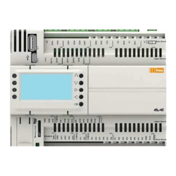
Lync AEGIS Controller 8: APPENDIX D 8. APPENDIX D 8.1. Operation With Built-In Display The PLC that operates the Aegis has a built-in display. This is accessible from inside the electrical enclosure. W A R N I N G ! The electrical enclosure must be powered on to operate the PLC. -
Page 65: Menu Navigation
Lync AEGIS Controller 8: APPENDIX D RIGHT () When displaying: displays lower-level screen. When editing: selects right number. LEFT () When displaying: returns to higher-level screen. When editing: selects left number. When displaying: confirmation key. When editing: start/enter. 8.4. Menu Navigation Press the RIGHT key on the home page or on the general data screen to access the main menu, which can be scrolled through with the UP and DOWN keys. -
Page 66: General Data Screen
Lync AEGIS Controller 8: APPENDIX D ● ● ● ⑨ Compressor status Utility water outlet temperature: HW out ● ● ● ⑩ ● ● ● ⑪ Current date ● ● ● ⑫ Current time Press the BACK key to return to the general information page. The home page is automatically displayed again after a few seconds. -
Page 67: Switching On/Off From Digital Input
Lync AEGIS Controller 8: APPENDIX D ● ● ● 9109 Oil temperature °C ● ● ● 8975 Evap Evaporation temperature °C ● ● ● 8974 SpHeat Superheating °C Compressor discharge ● ● ● 9674 Disch °C temperature ● ● 9079... -
Page 68: Digital Input - "Hw Request
Lync AEGIS Controller 8: APPENDIX D • in the 0 or OFF position the unit is always OFF; • in the “MAN” position the unit is ON but the control is bound to the state of the analog/digital inputs; •... - Page 69 Lync AEGIS Controller 8: APPENDIX D By setting ON the “Enable supervision” variable (parameter RC01) the digital input ID1 (general ON-OFF) is ignored, and the unit ON/OFF switching can be controlled by the parameter RC02. The variable "Hot water request by:" (parameter RC03) is used to select whether hot water demand for the user) is given by the status of the digital input ID2 or by the external supervising controller input.
-
Page 70: Main Menu
Lync AEGIS Controller 8: APPENDIX D 8.9. Main Menu The following sub-menus, which may be displayed or not depending on the operating mode, are enabled in this menu. A/W with Index Menu Action recovery accesses user parameters settings: work set point, ●... -
Page 71: Menu - A Settings
Lync AEGIS Controller 8: APPENDIX D ● ● ● Warnings displays the active warnings ● ● ● Alarms log displays the alarms logger ● ● Defrost displays the defrost status accesses the date and time ● ● ● Clock set... -
Page 72: Menu - Aa Set Point
Lync AEGIS Controller 8: APPENDIX D accesses the cold water recovery settings, enabling ● CW recovery commands, set point and differential. C A U T I O N ! Settings should be adjusted by taking into account the configuration of the system, the use for which the unit is designed, and the unit’s operating limits. - Page 73 Lync AEGIS Controller 8: APPENDIX D Modbus Read Unit of address Write Code Meaning Min Max measurement 16633 ST02 Enables BT1 probe OFF ON 16633 16637 ST03 BT1 probe set point 20 85 / 90 * °C BT1 probe 16639 ST04 °C...
-
Page 74: Menu - Ac Cw Recovery (Cool Recovery)
Lync AEGIS Controller 8: APPENDIX D • press the OK key to confirm changes and close the set point screen. In the differential temperature windows (parameters ST04 – ST07): • press the UP key to increase the value by 0.1°C (32.1°F);... -
Page 75: Menu - B I/O Values
Lync AEGIS Controller 8: APPENDIX D • press the UP key to set the value ON; • press the DOWN key to set the value OFF; • press the BACK key to cancel the choice and return to the Ac.CW Recovery menu;... -
Page 76: Menu - Ba Analog Inputs
Lync AEGIS Controller 8: APPENDIX D On the main menu, with the B.I/O VALUES menu selected, press the RIGHT key to access the sub-menu where more screens can be selected with the UP and DOWN keys. A/W with Index Menu... -
Page 77: Menu - Bb Analog Inputs
Lync AEGIS Controller 8: APPENDIX D function” temp ● ● ● Refrigerant high 8344 pressure Refrigerant low pressure ● ● ● 8345 AI10 LP ● ● ● 8346 AI11 Oil Oil temp °C ● ● ● Compressor discharge 8347 AI12 Disch °C... -
Page 78: Menu - Bd Digital Outputs
Lync AEGIS Controller 8: APPENDIX D ● ● ● 8192 ON-OFF Remote ON-OFF ● ● ● 8193 Hot utility request Request ● 8194 Cold utility request Request ● ● 8195 Force DF Forced defrost ● ● ● 8196 HP Switch High pressure switch ●... -
Page 79: Menu - C Alarms
Lync AEGIS Controller 8: APPENDIX D ● ● ● 8533 HW Heater Utility anti-ice heater ● 8534 RW Heater Recovery anti-ice heater ● 8534 SW Heater Source anti-ice heater ● ● 8535 Defrost Defrost ● 8536 LR Heater Receiver heaters ●... - Page 80 Lync AEGIS Controller 8: APPENDIX D ● ● ● 9604 9079 High suction temperature HSuc ● ● ● Maximum gas cooler temperature (from 9608 9074 GC HT temperature probe) ● ● ● Oil level low (from digital 9592 9123 OL Lev input) ●...
-
Page 81: Menu - D Warnings
Lync AEGIS Controller 8: APPENDIX D with double probe) ● ● Recovery side inlet probe 9623 8999 Er CWi alarm ● Recovery side outlet probe 9624 8981 Er CWo alarm ● Source water outlet probe 9612 8981 Er SWo error ●... -
Page 82: Menu - E Alarms Log
Lync AEGIS Controller 8: APPENDIX D ● ● Recovery/source side temperature 8984 CW HD difference above maximum ● ● Recovery/source side temperature 8989 CW LD difference below minimum ● ● ● 9112 Er OL Oil probe error ● ● ●... - Page 83 Lync AEGIS Controller 8: APPENDIX D • minimum interval before the next defrost operation Defrosting starts when the evaporation temperature drops below the defrost starting threshold. Use the UP and DOWN keys to scroll through the three pages describing defrost operation.
-
Page 84: Menu - G Clock Set
Lync AEGIS Controller 8: APPENDIX D page) Drop-off phase (visible only on the home 9561 page) Interval phase between 2 defrost operations 9563 (visible only on the home page) 16665 Type of Defrost (dynamic/fixed) 8975 Actual evaporation temperature °C 9564 Defrost start evaporation temperature °C... -
Page 85: Service Menu
Lync AEGIS Controller 8: APPENDIX D 8.10. Service Menu C A U T I O N ! Only qualified staff should edit the service parameters. Changing these parameters may lead to malfunction and/or serious damage to the unit. Press “Service” on the main menu to access the service menu. Press the RIGHT key to access the window where a password must be entered to access the sub-menus. -
Page 86: Menu - St Set Point
Lync AEGIS Controller 8: APPENDIX D ● ● ● BACnet IP configuration ● ● Condenser tray heaters settings ● ● ● Secondary hydraulic circuit settings ● ● Force defrost 8.10.1. Menu - St Set Point On the service menu, with the ST key selected, press the OK key to access the screen used to set the hot water set point and enable the double probe function and its set points and differentials. - Page 87 Lync AEGIS Controller 8: APPENDIX D 0 = OFF Anti-freeze alarm ● ● ● 16644 RW AI06 enabling 1 = ON Hot water side anti- ● ● ● 16642 RW AI07 freezealarm: alarm -15 10 °C activation set point Hot water side anti- freeze alarm: alarm ●...
-
Page 88: Hot Side Anti-Freeze
Lync AEGIS Controller 8: APPENDIX D probe) Cold water side anti- freeze alarm activation ● ● 16825 RW AI16 °C differential (regulation on inlet probe) 8.11. Hot Side Anti-Freeze The hot side anti-freeze function is managed by parameters AI01-AI08. Parameter AI01 is used to select on which probe (external air or water inlet) the hot side anti-freeze heaters and the anti-freeze alarm are activated. - Page 89 Lync AEGIS Controller 8: APPENDIX D Parameter AI06 is used to select whether to activate the hot side anti-freeze alarm. If parameter AI06 = 1 (ON), the external air probe or utility water inlet value (depending on parameter AI01) is compared with the difference between the values of parameters AI07 and AI08.
-
Page 90: Cold Side Anti-Freeze (Recovery/Source)
Lync AEGIS Controller 8: APPENDIX D 8.12. Cold Side Anti-Freeze (Recovery/Source) The cold side anti-freeze is managed by parameters AI09-AI16. The reference probe for operation of the anti- freeze heater and the anti-freeze alarm is the cold recovery heat exchanger water / source water outlet probe. Parameters AI09 and AI10 control activation of the cold water side anti-freeze heater on the outlet probe reading. - Page 91 Lync AEGIS Controller 8: APPENDIX D 16124 R/W MD01 RS485 no. 1 - Address 1 16125 R MD02 RS485 no. 1 - 3 = Modbus/RTU Protocol 4 = BACnet MS/TP 16126 R MD03 RS485 no. 1 - Data bit 8...
- Page 92 Lync AEGIS Controller 8: APPENDIX D Warnings For The Realization Of Network Rs-485 • Perform all installation and maintenance work with the unit switched off; • Use shielded wires for serial connections: 2 wires + shield; do not make star connections (use chain connections);...
-
Page 93: Menu - Et Ethernet
Lync AEGIS Controller 8: APPENDIX D Lay down the cable in dedicated cable rails, as far as possible to power cables. In order to avoid disturbances, it has to be placed far from sources of electrical noise: • Radio antennas •... -
Page 94: Menu - Df Defrost
Lync AEGIS Controller 8: APPENDIX D 15806 Net Mask first part 15807 Net Mask second part 15808 Net Mask third part 15809 Net Mask fourth part 15818 DHCP enabling 0 = OFF 1 = ON Reboot the controller (switch it off and back on) for the new values to take effect. -
Page 95: Forced Defrost
Lync AEGIS Controller 8: APPENDIX D The dynamic evaporation temperature calculates a value that depends on the DF02 defrost starting set point, the DF04 external air temperature, and on the DF03 and DF04 differentials, according to the above graph. Other parameters than can be set are: •... -
Page 96: Menu - Cr Cold Recovery
Lync AEGIS Controller 8: APPENDIX D • Press the OK key to confirm forcing the defrost cycle; • press the BACK key to close the window without confirming selection for forcing the defrost cycle. 8.12.10. Menu - Cr Cold Recovery On the service menu, with the CR key selected, press the OK key to access the screen used to set the cold recovery parameters. -
Page 97: Menu - Ba Bacnet Ip
Lync AEGIS Controller 8: APPENDIX D The available parameters are used to set the warnings that indicate if the difference between water inlet and outlet on the source heat exchanger is within certain limits. Parameter SW04 defines the warning delay from compressor start-up. -
Page 98: Menu - Cth - Condenser Tray Heaters
Lync AEGIS Controller 8: APPENDIX D Use the RIGHT and BACK keys to move between the pages. Modbus Read address Write Code Meaning 17284 R/W BN01 BACnet IP enable 17282 R/W BN02 Device instance 17283 R/W BN03 BACnet subnet 17285 R/W... -
Page 99: Menu - Shc - Secondary Hydraulic Circuit
Lync AEGIS Controller 8: APPENDIX D On the service menu, with the CTH key selected, press the OK key to access the screen used to set the Condenser tray heaters parameters. Modbus Address Read Write Code Meaning 17363 CTH01 Enable condenser tray heaters OFF Activation temperature set 20.0... - Page 100 Lync AEGIS Controller 8: APPENDIX D L-OMM-013_A • 4/20/2022Technical Support • (800) 433-5654 • Mon-Fri, 8 am - 5 pm EST 100 of 100...
Need help?
Do you have a question about the Lync AEGIS Controller and is the answer not in the manual?
Questions and answers