Table of Contents
Advertisement
Quick Links
Advertisement
Table of Contents

Subscribe to Our Youtube Channel
Related Manuals for Watts tekmar 294


![Controller Watts AERCO Edge [ii] Operation Manual](https://static-data2.manualslib.com/product-images/da1/2085997/60x60/watts-aerco-edge-ii-controller.jpg)


Summary of Contents for Watts tekmar 294
- Page 1 IOM-T-294 Installation, Operation and Maintenance Manual Smart Boiler Control 294 WARNING Please read carefully before proceeding with installation. Your failure to follow any attached instructions or operating parameters may lead to the product’s failure. Keep this Manual for future reference.
-
Page 2: Table Of Contents
Table of Contents Important Safety Information . . . . . . . . . . . . . . . . . . . . . . . . . 3 Sequence of Operation . -
Page 3: Important Safety Information
Important Safety Information It is your responsibility to ensure that this control is safely • It is the installer’s responsibility to ensure that this control installed according to all applicable codes and standards . is safely installed according to all applicable codes and tekmar is not responsible for damages resulting from standards . -
Page 4: Radio Frequency Statement
Radio Frequency Statement This equipment has been tested and found to comply with the limits for a Class A digital device, pursuant to part 15 of the FCC Rules . These limits are designed to provide reasonable protection against harmful interference when the equipment is operated in a commercial environment . -
Page 5: Installation
Installation Installation Location When choosing the location for the control, consider the following: • Provide easy access for wiring, viewing, and adjusting the display screen . • Keep dry . Avoid potential leakage onto the control . 90% to 104°F (40°C) . •... -
Page 6: Wiring Schematic
For product literature: Relays: Pour la documentation 230 V (ac), 5 A, 1/3 hp du produit: Calls: Watts.com/tekmar 24 V (ac) or Short Operating Temperature: 32°F to 122°F (0°C to 50°C) tektra 1150-01 Designed and assembled Use Copper Conductors Only... -
Page 7: Wiring Instructions
Wiring Instructions This section explains how to wire individual devices to the Smart Boiler Control 294 . Pressure Sensor 088 (Terminals 1, 2, 3) An optional Pressure Sensor 088 (sold separately) can connect to the 294 to provide pressure monitoring for hydronic systems up to 150 psi (1034 kPa) . The pressure sensor requires the installation of a tee with a ⁄... - Page 8 EMS Connection (Terminals 4, 5) An Energy Management System (EMS) can be connected to the 294 to provide a target water temperature . This signal replaces the outdoor air temperature sensor . Either a 0 to 10 V (dc) or 2 to 10 V (dc) signal may be used .
-
Page 9: Testing The Sensor Wiring
Boiler Sensor (Terminals 6, 7) The included Universal Sensor 082 can measure the boiler supply temperature of water coming from the boiler system . This sensor should be installed on the supply pipe ahead of the tees supplying any loads . •... - Page 10 Central Heat Call (Terminals 10, 11) A central heat call is required whenever the building requires heating . The heat call can be volt free or up to 24 V (ac) . • Connect the Central Heat Call terminals 10 and 11 to a switched heat demand . •...
- Page 11 tekmarNet4 Boiler Bus (Terminals 16, 17) tekmarNet4 (tN4) is a wired communication network for tekmar thermostats, setpoint controls and snow melting controls to communicate to the boiler control . The network provides central heating calls, DHW calls and setpoint calls as a digital message between tekmar devices .
- Page 12 Modulating Boilers (Terminals 25 to 32) The control provides either a 0-10 V (dc) or a 4-20 mA output to each boiler . Polarity is important . • Connect the control Mod (+) terminals 25, 27, 29, 31 to boilers 1, 2, 3 and 4 analog signal input Boiler 1 (+) respectively .
- Page 13 Boiler Pump / Valve (Terminals 41 to 48) Boiler pumps or valves requiring up to can be switched through terminals 41 230 V (ac) 5 A, 1/3 hp to 46 . If a single power source is used for multiple pumps, ensure they are not tied together at any point between the pumps and the control .
- Page 14 System Pump (Terminals 51, 52) A system pump requiring up to 230 V (ac) 5 A, ⁄ hp can be switched through terminals 51 and 52 . For simplicity in wiring and troubleshooting, a separate breaker for each pump is recommended . System •...
-
Page 15: User Interface
User Interface Power On • When first powered on, the tekmar logo appears . • If the display does not turn on, please contact your tekmar sales representative or technical support for assistance . Lock Screen • When first powered on, the tekmar logo appears followed by the lock screen . -
Page 16: Home Screen
Blue indicates connection to Wi-Fi . control for boilers 5 to 16 . WATTS ONSITE NOTIFICATIONS BELL Blue indicates connection to the Watts When displayed, it indicates an error or ® OnSite cloud service . warning notification is present . -
Page 17: System Inputs Screen
System Inputs Screen • When a call for heat is active, the dot is green . • When there is no call for heat, the dot is gray . • The central heating and setpoint targets are for the boiler system . •... -
Page 18: Boiler Status List Screen
Boiler Status List Screen … • Press ellipsis to go to the Boiler Status Carousel screen • The circle in blue indicates the boiler firing rate percent or boiler target temperature • Press the boiler hour number to go to the Boiler Hours screen •... -
Page 19: Menu Screen
Menu Screen Navigation BACK SKIP SKIP arrow-le Go back a level without saving Skip step in Setup Wizard or Wi-Fi Setup HOME BEGIN BEGIN Go to Home screen without saving Begin the Setup Wizard SAVE NEXT SAVE NEXT Saves the new setting value Go to the next step CLEAR CLEAR... -
Page 20: Menus
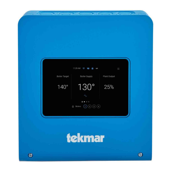
Menus Home Screen Parameter Range Description ---, -22 to 266°F Current boiler supply water temperature as measured by the boiler supply sensor . “---” BOILER SUPPLY is displayed if there is a sensor fault . (-30 to 130°C) ---, -22 to 266°F The boiler target is the temperature the control is trying to maintain at the boiler supply BOILER TARGET sensor . -
Page 21: Settings Menu
Select the desired Wi-Fi network SSID . Then enter the Wi-Fi password . networks WATTS ONSITE Register or Deregister Register the control with Watts OnSite to use the web or mobile apps . DHCP or Static Select if the control should receive an automatic IP address from the router DHCP CONFIGURATION server or use a static IP address . - Page 22 Settings (2 of 8) Parameter Range Description HEATING CALLS > CENTRAL HEATING Off or On Select if the control responds to central heating calls . When connected to a CENTRAL HEATING tekmarNet system, this setting is forced on and not visible . Default: Off 35 to 100°F ROOM...
- Page 23 Settings (3 of 8) Parameter Range Description 50 to 230°F DHW TANK Set the DHW tank temperature during the unoccupied period . Available when DHW (10 .0 to 110 .0°C) UNOCCUPIED Sensor is set On . Default: 130°F (54 .5°C) 1 to 42°F Set the DHW tank differential .
- Page 24 Settings (4 of 8) Parameter Range Description Based on presets file BOILER Select the boiler manufacturer . Choose Custom if the installed boiler is not included MANUFACTURER in the list . Default: Custom BOILER SERIES Based on presets file Select the boiler series . Available when a boiler manufacturer name is selected . BOILER MODEL Based on presets file Select the boiler model .
- Page 25 Settings (5 of 8) Parameter Range Description 0 .0 to 20 .0 minutes POST PURGE Set the boiler pump post purge time after the burner has shut off . Default: 2 .0 minutes SYSTEM The minimum allowed boiler target temperature used for the non-condensing boiler 50 to 230°F group .
- Page 26 Settings (6 of 8) Parameter Range Description Off or On Select if boiler 1 is always the first boiler to fire . This feature is useful in cases whereby FIXED LEAD boiler 1 primes the flue gas venting . Default: Off First On/First Off or First On/Last Off Select if boiler 1 is the first on/first off or first on/last off .
- Page 27 Settings (7 of 8) Parameter Range Description BOILER 1 SERVICE 1000 to 25000 hours Set the number of boiler running hours above which the control triggers a boiler HOURS ALERT Default: 5000 hours service alert notification . BOILER 1 SERVICE 1 to 25000 cycles Set the number of boiler on/off cycles above which the control triggers a boiler CYCLES ALERT...
- Page 28 RESET FACTORY RESET Select to load factory defaults for all settings . This does not deregister the control from the Watts OnSite application . TEKMARNET Select to reset the tekmarNet communications . This removes any lost tN4 devices from the control .
-
Page 29: Schedule Menu
Schedule Menu The control can follow an internal schedule to provide energy savings during unoccupied periods . When creating a new schedule, choose the days that share the same occupied and unoccupied time periods . Parameter Range Description 12:00 am to 12:50 pm OCCUPIED 1 (0:00 to 23:50) Set the occupied 1 time . -
Page 30: Notifications Menu
Notifications Menu The control keeps track of the last 30 errors and alert notifications . Refer to the Troubleshooting section for corrective action . Overrides Menu Parameter Range Description Set the manual override . Automatic reverts to normal operation . Hand allows each output to be turned on or set manually . - Page 31 Override Menu Commissioning, testing and troubleshooting features of the 294 are accessed through the Override menu . The Manual Override has five different modes including: Automatic The normal operating mode for the control is automatic . Purge Override In this mode, the control overrides the normal operating mode and operates pumps .
-
Page 32: About Menu
About Menu The About menu lists all details about the control . This information may be required when contacting tekmar for support . Help Menu Scan the QR code with your mobile phone to be directed to the product website to find specifications, manuals, and videos . -
Page 33: Sequence Of Operation
Sequence of Operation Heating Calls When powered on and in automatic mode, the control remains in standby until it receives a heating call from one of the following inputs: • Central heating call • Domestic hot water call • Setpoint call •... - Page 34 Terminal Unit Defaults Baseboard A baseboard or convector terminal unit is made up of a heat- When a terminal unit is selected the control loads default val- ing element with fins on it . This type of terminal unit relies on ues for the boiler design, boiler maximum supply, and boiler the natural convection of air across the heating element to minimum supply temperatures .
-
Page 35: Domestic Hot Water (Dhw) Operation
Domestic Hot Water (DHW) Operation DHW Call DHW Type System Operation A domestic hot water (DHW) call operates the boilers at a fixed The indirect DHW tank is piped in the boiler system loop . When temperature to heat a DHW storage tank . The DHW call status a DHW call is present, the DHW Pump turns on . -
Page 36: System Setup And Operation
DHW Priority temperature system while trying to satisfy the DHW call . This may result in damage to the low temperature heating system . The Indirect DHW Priority setting selects priority over the cen- The control is capable of providing DHW heating in such a tral heating system . - Page 37 Dedicated Domestic Hot Water Operation The control can operate water heaters to provide heat in an open-loop dedicated domestic hot water system . This is selected by setting DHW Type to Dedicated . When dedicated is selected, all other heating calls are disabled . DHW Call A DHW sensor installed in a temperature well to measure the tank temperature is used to create a DHW call .
-
Page 38: Constant Setpoint Operation
Constant Setpoint Operation Setpoint Call Setpoint Priority A setpoint call operates the boilers to a constant temperature set- The Constant Setpoint Priority setting selects whether or not point . The setpoint call status is displayed in the System Inputs on priority of setpoint over central heating is required . -
Page 39: Remote Setpoint Call
Remote Setpoint Call 2-10 V(dc) or 4-20 mA The control accepts an analog signal to create a Remote Setpoint Call when a 0-10 V(dc), 2-10 V(dc), or 4-20 mA signal When Input EMS Signal is set to 2 - 10 V (dc), the control uses is applied to the EMS (+) and EMS (-) wiring terminals . -
Page 40: Boiler Operation
Boiler Operation The 294 can operate four boilers and up to 16 boilers when used Example: If boiler 1 is set to 4-stage, then boiler enables 1, 2, together with the three Smart Boiler Expansion 294EXP . Each 3 and 4 are used . boiler is configured individually to provide maximum flexibility . - Page 41 High 10 V (dc) 10 V (dc) 100% Select High mass for large commercial boilers . This provides long pre and post purge times for the pumps, modulates the boiler quickly, and operates the boiler staging with long inter- Boiler’s Input Control’s stage delays .
-
Page 42: Boiler Modbus Communication
Boiler Modbus Communication The control includes a modbus port to communicate to boilers . This allows the control to read the lockout and/or hold error codes from the boiler . These error codes are recorded in the notification menu, and if connected to the Internet, the notifica- tion is sent as an email, SMS text or push notification . -
Page 43: System Operation
System Operation The Smart Boiler Control 294 is able to operate up to four boil- perature reaches 1/2 of the differential above the boiler target ers and can be expanded up to a maximum of sixteen boilers temperature, the boiler is shut off . through the use of Smart Boiler Expansion 294EXP . - Page 44 Interstage Differential Parallel Sequencing Select the temperature drop from the prior boiler turning on With Parallel sequencing, the control will turn on the most to turn on the next boiler stage . The first boiler turns on when boilers at the minimum firing rate . The control turns on the the boiler supply temperature drops the Interstage Differential first boiler at the minimum firing rate and does not increase its below the boiler target .
- Page 45 Boiler Group Rotation Boiler Plant Flow The control has two boiler rotation groups: The control supports the option of having all boilers in the plant to use either a pump or an isolation valve . • Condensing Boiler Rotation Group Boiler Pump •...
-
Page 46: Pump Operation
Pump Operation System Pump Operation Remote Setpoint Call The system pump operates whenever there is a remote set- The control includes a system pump that can operate point call . whenever there is a call for heat . System Pump Purge Central Heating Call The system pump turns on together with the central The system pump includes a post-purge after a heating call is... -
Page 47: Schedule
Schedule To provide greater energy savings, the control can operate on a programmable 7-day, 4-event schedule . The schedule is stored in memory and is not affected by loss of power to the control . Time Clock When connected to the Internet, the control automatically sets its time to the Eastern time zone by default . This can be changed to one of the applicable North American time zones . -
Page 48: Troubleshooting
Troubleshooting It is recommended to complete all wiring to ensure trouble free operation . Should an error occur, simply follow these steps: 1 . Find: If a banner is on the screen, it is indicating a problem on the system . 2 . - Page 49 Errors and Alerts (2 of 4) Error Title Description The control has not received an outdoor temperature report from the tekmarNet network . Check the tekmarNet tekmarNet Outdoor network for the location of the outdoor sensor measurement . Check the sensor for open or short circuits Sensor Error and replace the Outdoor Sensor 070 if necessary .
- Page 50 2 . Check that the router firewall is not blocking or filtering MAC addresses 3 . Check that the router firewall is not blocking outbound port 23 The control is unable to connect to Watts OnSite . Please check that your router is not blocking outbound ports Watts OnSite Error ®...
- Page 51 Error Messages (4 of 4) Error Title Description The control has detected a problem with the boiler modbus communication . Check the modbus wire polarity, Modbus Bus Error the cable length, connection to the boiler, and connection of any terminating resistors . Modbus Boiler 01 to 16 The control is unable to communicate to Boiler 01 to 16 through Modbus .
-
Page 52: Technical Data
Technical Data Smart Boiler Control 294 Literature Submittal, Application, Installation and Operating Manual, Job Record, Watts OnSite Manual Packaged weight 3.3 lb. (1500 g) Dimensions 9" H x 8" W x 2 ⁄ " D (229 x 203 x 60 mm) Display 5"...
Need help?
Do you have a question about the tekmar 294 and is the answer not in the manual?
Questions and answers