Table of Contents
Advertisement
Quick Links
Advertisement
Table of Contents

Related Manuals for AUMA SQVEx 05.2


Summary of Contents for AUMA SQVEx 05.2
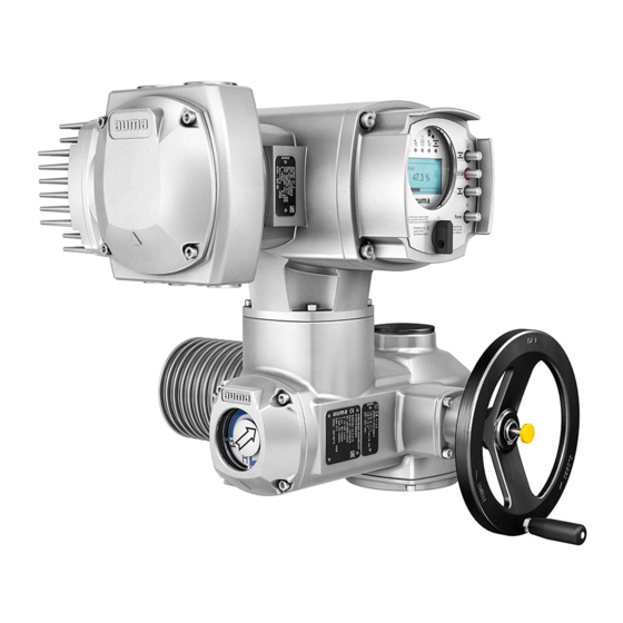
- Page 1 Part-turn actuators SQVEx 05.2 SQVEx 14.2 SQRVEx 05.2 SQRVEx 14.2 Control unit: electronic (MWG) with actuator controls ACVExC 01.2 Non-Intrusive Control Parallel Profibus DP Modbus RTU Modbus TCP/IP Foundation Fieldbus HART Operation instructions Assembly, operation, commissioning...
-
Page 2: Table Of Contents
This document contains information for assembly, commissioning and maintenance staff. Reference documents: Manual (Operation and setting) of actuator controls ACVExC 01.2 Modbus Manual (Fieldbus device integration) of actuator controls ACVExC 01.2 Modbus Reference documents are available on the Internet at: http://www.auma.com. Table of contents Page Safety instructions......................... - Page 3 Indications during commissioning 8.2. Indications in the display 8.2.1. Feedback signals from actuator and valve 8.2.2. Status indications according to AUMA classification 8.2.3. Status indications according to NAMUR recommendation 8.3. Indication lights of local controls 8.4. Mechanical position indication (self-adjusting) 8.5.
- Page 4 Technical data Part-turn actuator 14.2. Technical data Actuator controls 14.3. Tightening torques for screws Spare parts..........................15.1. Part-turn actuators SQVEx 05.2 SQVEx 14.2/SQRVEx 05.2 SQRVEx 14.2 KT/KM 15.2. ACVExC 01.2 KT/KM actuator controls 15.3. ACVExC 01.2 KP/KPH actuator controls 15.4.
-
Page 5: Safety Instructions
SQVEx 05.2 SQVEx 14.2/ SQRVEx 05.2 SQRVEx 14.2 Control unit: electronic (MWG) ACVExC 01.2 Modbus RTU Safety instructions Safety instructions 1.1. Prerequisites for the safe handling of the product The end user or the contractor must ensure that all legal requirements, directives,... -
Page 6: Range Of Application
1, 2, 21, and 22. If temperatures >40 °C are to be expected at the valve flange or the valve stem (e.g. due to hot media), please consult AUMA. Temperatures > 40 °C are not considered with regard to the non-electrical explosion protection. -
Page 7: Warnings And Notes
SQVEx 05.2 SQVEx 14.2/ SQRVEx 05.2 SQRVEx 14.2 Control unit: electronic (MWG) ACVExC 01.2 Modbus RTU Safety instructions 1.3. Warnings and notes The following warnings draw special attention to safety-relevant procedures in these operation instructions, each marked by the appropriate signal word (DANGER, WARNING, CAUTION, NOTICE). -
Page 8: Short Description
App and software Using the AUMA CDT software for Windows-based computers (notebooks or tablets) and the AUMA Assistant App, actuator data can be uploaded and read, settings can be modified and stored. The connection between computer and AUMA actuator is established wireless via Bluetooth interface. With the AUMA Cloud, we provide an interactive platform to collect and assess e.g. - Page 9 The AUMA Cloud is the driving element of the digital AUMA world, acting as interactive platform for efficient maintenance of AUMA actuators at moderate cost. The AUMA Cloud collects all device data of all actuators within one site and provides a clear overview at a glance. Detailed analysis provides valuable information on potential maintenance requirements.
-
Page 10: Name Plate
SQVEx 05.2 SQVEx 14.2/ SQRVEx 05.2 SQRVEx 14.2 Control unit: electronic (MWG) Name plate ACVExC 01.2 Modbus RTU Name plate Figure 4: Arrangement of name plates Actuator name plate Actuator controls name plate Motor name plate Additional plate, e.g. KKS plate (Power Plant Classification System) - Page 11 SQVEx 05.2 SQVEx 14.2/ SQRVEx 05.2 SQRVEx 14.2 Control unit: electronic (MWG) ACVExC 01.2 Modbus RTU Name plate Actuator controls name plate Figure 6: Name plate for actuator controls (example) (= manufacturer logo) Type designation Order number Serial number Actuator terminal plan...
- Page 12 Please always state this number for any product inquiries. On the Internet at http://www.auma.com > Service & Support >myAUMA, we offer a service allowing authorised users to download order-related documents such as wiring diagrams and technical data (both in German and English), inspection certificate and the operation instructions when entering the order number.
- Page 13 Control via Modbus RTU interface and control voltage for OPEN-CLOSE control via digital inputs (OPEN, STOP, CLOSE) When registered as authorised user, you may use our AUMA Assistant App to scan Data Matrix code the Data Matrix code and directly access the order-related product documents without having to enter order number or serial number.
-
Page 14: Transport, Storage And Packaging
SQVEx 05.2 SQVEx 14.2/ SQRVEx 05.2 SQRVEx 14.2 Control unit: electronic (MWG) Transport, storage and packaging ACVExC 01.2 Modbus RTU Transport, storage and packaging 4.1. Transport For transport to place of installation, use sturdy packaging. Suspended load! Death or serious injury. -
Page 15: Storage
SQRVEx 10.2 SQVEx 12.2/ SQRVEx 12.2 SQVEx 14.2/ SQRVEx 14.2 Indicated weight includes AUMA NORM part-turn actuator with 3-phase AC motor, electrical con- nection in standard version, unbored coupling and handwheel. For other output drive types, consider additional weights. 4.2. Storage Risk of corrosion due to inappropriate storage! Store in a well-ventilated, dry room. -
Page 16: Assembly
SQVEx 05.2 SQVEx 14.2/ SQRVEx 05.2 SQRVEx 14.2 Control unit: electronic (MWG) Assembly ACVExC 01.2 Modbus RTU Assembly 5.1. Mounting position When using grease as lubricant, the product described herein can be operated in any mounting position. When using oil instead of grease within the actuator gear housing, perpendicular mounting position is specified whereby the flange is pointing downward. -
Page 17: Overview On Coupling Variants
SQVEx 05.2 SQVEx 14.2/ SQRVEx 05.2 SQRVEx 14.2 Control unit: electronic (MWG) ACVExC 01.2 Modbus RTU Assembly 5.3.1. Overview on coupling variants Design Figure 11: Valve attachment via coupling Bore with keyway Square bore Bore with two-flats For valve attachments according to EN ISO 5211... - Page 18 Valve shaft Grub screw Clamping washer and screw with curved spring lock washer Figure 13: Mounting positions for coupling Table 6: Mounting position of the coupling within fitting dimensions according to AUMA definition Dimensions [mm] SQEx 05.2 SQEx 07.2 SQEx 10.2 SQEx 12.2...
- Page 19 SQVEx 05.2 SQVEx 14.2/ SQRVEx 05.2 SQRVEx 14.2 Control unit: electronic (MWG) ACVExC 01.2 Modbus RTU Assembly Fit actuator. If required, slightly turn actuator until splines of coupling engage. Figure 14: Ensure that the spigot (if provided) fits uniformly in the recess and that the flanges Information are in complete contact.
-
Page 20: Mounting Positions Of Local Controls
SQVEx 05.2 SQVEx 14.2/ SQRVEx 05.2 SQRVEx 14.2 Control unit: electronic (MWG) Assembly ACVExC 01.2 Modbus RTU 5.4. Mounting positions of local controls Figure 15: Mounting positions The mounting position of the local controls is implemented according to the order. -
Page 21: Electrical Connection
It can plan also be requested from AUMA (state order number, refer to name plate) or downloaded directly from the Internet (http://www.auma.com). The actuators are suitable for use in TN and TT networks with directly grounded star Permissible networks point for nominal voltages up to maximum 480 V AC. - Page 22 SQVEx 05.2 SQVEx 14.2/ SQRVEx 05.2 SQRVEx 14.2 Control unit: electronic (MWG) Electrical connection ACVExC 01.2 Modbus RTU Table 8: Protection on site Part-turn actu- 3-phase AC motor 380 V 480 V/50 Hz 60 Hz Fuse ator Consumed rated Blow characteristics:...
-
Page 23: Overview Of Auma Electrical Connections
Baud rate (kbit/s) Maximum cable length: between two network participants for copper cables 10/100 Mbits/s 100 m 6.2. Overview of AUMA electrical connections The section below provides an overview of the different electrical connections described in the chapters to follow. -
Page 24: Kt/Km Electrical Connection
SQVEx 05.2 SQVEx 14.2/ SQRVEx 05.2 SQRVEx 14.2 Control unit: electronic (MWG) Electrical connection ACVExC 01.2 Modbus RTU Table 12: Versions of the AUMA plug/socket connector Electrical con- Figure Properties For description nection and assembly refer to chapter Plug-in integral terminal connection ➭... -
Page 25: Terminal Compartment: Open
SQVEx 05.2 SQVEx 14.2/ SQRVEx 05.2 SQRVEx 14.2 Control unit: electronic (MWG) ACVExC 01.2 Modbus RTU Electrical connection KM version with additional support terminals (terminal blocks) via terminal carrier. When using solid fieldbus cables in line topology, imperatively use support terminals. -
Page 26: Cable Connection
SQVEx 05.2 SQVEx 14.2/ SQRVEx 05.2 SQRVEx 14.2 Control unit: electronic (MWG) Electrical connection ACVExC 01.2 Modbus RTU Procedure Electric shock due to presence of hazardous voltage! Death or serious injury. Disconnect device from the mains before opening. Wait for 30 seconds after power cut-off prior to opening the housing. - Page 27 SQVEx 05.2 SQVEx 14.2/ SQRVEx 05.2 SQRVEx 14.2 Control unit: electronic (MWG) ACVExC 01.2 Modbus RTU Electrical connection Connect cables according to order-related wiring diagram. Figure 21: Connect cables to terminal carrier Fitting control cables into spring clamp terminals Tightening power terminals...
- Page 28 SQVEx 05.2 SQVEx 14.2/ SQRVEx 05.2 SQRVEx 14.2 Control unit: electronic (MWG) Electrical connection ACVExC 01.2 Modbus RTU In case of a fault, electric shock due to presence of hazardous voltage if the PE conductor is NOT connected! Risk of death or serious injury! Connect all protective earth conductors.
-
Page 29: Fieldbus Cables: Connect
SQVEx 05.2 SQVEx 14.2/ SQRVEx 05.2 SQRVEx 14.2 Control unit: electronic (MWG) ACVExC 01.2 Modbus RTU Electrical connection 6.3.3. Fieldbus cables: connect 6.3.3.1. Fieldbus connection for line topology Figure 23: Line topology □ Channel 1: Further fieldbus devices follow ▣... - Page 30 SQVEx 05.2 SQVEx 14.2/ SQRVEx 05.2 SQRVEx 14.2 Control unit: electronic (MWG) Electrical connection ACVExC 01.2 Modbus RTU Connection with support terminals for line topology When using solid cables (single or multiple strands), additional support terminals must be used.The support terminals (terminal blocks) are mounted above the terminal carrier.
-
Page 31: 6.3.3.2. Fieldbus Connection For Loop Topology
SQVEx 05.2 SQVEx 14.2/ SQRVEx 05.2 SQRVEx 14.2 Control unit: electronic (MWG) ACVExC 01.2 Modbus RTU Electrical connection 6.3.3.2. Fieldbus connection for loop topology Figure 28: Loop topology □ Channel 1 ▣ Channel 2 Last fieldbus device ■ Fieldbus cable from previous device (input) -
Page 32: Terminal Compartment: Close
SQVEx 05.2 SQVEx 14.2/ SQRVEx 05.2 SQRVEx 14.2 Control unit: electronic (MWG) Electrical connection ACVExC 01.2 Modbus RTU Figure 30: Terminal assignment of support terminals (2-channel) [XK] Terminal assignment according to wiring diagram (customer connection) □ Channel 1 ▣ Channel 2... -
Page 33: Kp/Kph Electrical Connection
SQVEx 05.2 SQVEx 14.2/ SQRVEx 05.2 SQRVEx 14.2 Control unit: electronic (MWG) ACVExC 01.2 Modbus RTU Electrical connection Fit cover [1] and fasten screws [2] evenly crosswise. For design in flameproof enclosure (Ex d): Flameproof enclosure, risk of explosion! Risk of death or serious injury! Handle cover and housing parts with care. -
Page 34: Terminal Compartment: Open
SQVEx 05.2 SQVEx 14.2/ SQRVEx 05.2 SQRVEx 14.2 Control unit: electronic (MWG) Electrical connection ACVExC 01.2 Modbus RTU Technical data Table 15: KP/KPH electrical connection Power contacts Control contacts No. of contacts max. 3 + protective earth conduct- 38 pins/sockets + protective earth con-... -
Page 35: Cable Connection
SQVEx 05.2 SQVEx 14.2/ SQRVEx 05.2 SQRVEx 14.2 Control unit: electronic (MWG) ACVExC 01.2 Modbus RTU Electrical connection Loosen screws [2] and remove cover [1]. How to proceed Insert cable glands suitable for connecting cables. Seal unused cable entries with approved plugs suitable for the required protec- tion type. -
Page 36: Fieldbus Cables: Connect
I or II) □ Channel 1: Further fieldbus devices will follow (standard) ▣ Channel 2: Further fieldbus devices will follow (AUMA redundancy I or II only) Last fieldbus device ■ Fieldbus cable from previous device (input) Fieldbus cable to next device (output) -
Page 37: Terminal Compartment: Close
2.1 Connect termination resistor for channel 1 through linking the terminals 31 - 33 and 32 - 34 (standard) 2.2 For AUMA redundancy I or II: Connect termination resistor for channel 2 through linking the terminals 35 - 37 and 36 - 38. -
Page 38: Kes Electrical Connection
SQVEx 05.2 SQVEx 14.2/ SQRVEx 05.2 SQRVEx 14.2 Control unit: electronic (MWG) Electrical connection ACVExC 01.2 Modbus RTU 6.5. KES electrical connection Figure 39: KES electrical connection Terminal blocks Connection frame Short description KES plug-in electrical connection with terminal blocks for power and control contacts. -
Page 39: Terminal Compartment: Open
SQVEx 05.2 SQVEx 14.2/ SQRVEx 05.2 SQRVEx 14.2 Control unit: electronic (MWG) ACVExC 01.2 Modbus RTU Electrical connection 6.5.1. Terminal compartment: open Figure 40: Open terminal compartment Cover (illustration shows type of protection Ex e) Screws for cover O-ring Blanking plugs... -
Page 40: Cable Connection
SQVEx 05.2 SQVEx 14.2/ SQRVEx 05.2 SQRVEx 14.2 Control unit: electronic (MWG) Electrical connection ACVExC 01.2 Modbus RTU 6.5.2. Cable connection Table 18: Terminal cross sections and terminal tightening torques Designation Terminal cross sections Tightening torques Power contacts (U, V, W) max. -
Page 41: Fieldbus Cables: Connect
I or II) □ Channel 1: Further fieldbus devices will follow (standard) ▣ Channel 2: Further fieldbus devices will follow (AUMA redundancy I or II only) Last fieldbus device ■ Fieldbus cable from previous device (input) Fieldbus cable to next device (output) -
Page 42: Terminal Compartment: Close
2.1 Connect termination resistor for channel 1 through linking the terminals 31 - 33 and 32 - 34 (standard) 2.2 For AUMA redundancy I or II: Connect termination resistor for channel 2 through linking the terminals 35 - 37 and 36 - 38. -
Page 43: External Earth Connection
SQVEx 05.2 SQVEx 14.2/ SQRVEx 05.2 SQRVEx 14.2 Control unit: electronic (MWG) ACVExC 01.2 Modbus RTU Electrical connection 6.6. External earth connection Figure 46: Earth connection for part-turn actuator Figure 47: Earth connection for wall bracket External earth connection (U-bracket) for connection to equipotential compensation. -
Page 44: Accessories For Electrical Connection
SQVEx 05.2 SQVEx 14.2/ SQRVEx 05.2 SQRVEx 14.2 Control unit: electronic (MWG) Electrical connection ACVExC 01.2 Modbus RTU 6.7. Accessories for electrical connection 6.7.1. Parking frame Figure 48: PAFEx 01.1 parking frame Parking frame for safe storage of a disconnected plug or cover. -
Page 45: Operation
SQVEx 05.2 SQVEx 14.2/ SQRVEx 05.2 SQRVEx 14.2 Control unit: electronic (MWG) ACVExC 01.2 Modbus RTU Operation Operation 7.1. Manual operation For purposes of setting and commissioning, in case of motor or power failure, the actuator may be operated manually. Manual operation is engaged by an internal change-over mechanism. -
Page 46: Actuator Operation From Remote
SQVEx 05.2 SQVEx 14.2/ SQRVEx 05.2 SQRVEx 14.2 Control unit: electronic (MWG) Operation ACVExC 01.2 Modbus RTU Figure 49: Local controls Push button for operation command in direction OPEN Push button STOP Push button for operation command in direction CLOSE... -
Page 47: Menu Navigation Via Push Buttons (For Settings And Indications)
SQVEx 05.2 SQVEx 14.2/ SQRVEx 05.2 SQRVEx 14.2 Control unit: electronic (MWG) ACVExC 01.2 Modbus RTU Operation Set selector switch to position Remote control (REMOTE). Now, the actuator can be remote-controlled via fieldbus. For actuators equipped with a positioner, it is possible to change over between OPEN... -
Page 48: Menu Layout And Navigation
SQVEx 05.2 SQVEx 14.2/ SQRVEx 05.2 SQRVEx 14.2 Control unit: electronic (MWG) Operation ACVExC 01.2 Modbus RTU Push buttons Navigation sup- Functions port on display [4] C Setup Enter Main menu Cancel process Return to previous display Backlight The display is illuminated in white during normal operation. It is illuminated in red in case of a fault. -
Page 49: User Level, Password
SQVEx 05.2 SQVEx 14.2/ SQRVEx 05.2 SQRVEx 14.2 Control unit: electronic (MWG) ACVExC 01.2 Modbus RTU Operation Figure 54: Direct display (example) Display indicates in the bottom row: Go to Press push button Go to. Display indicates: Go to menu M0000 Use push buttons Up ▲... -
Page 50: Password Change
A timeout for incorrect password entry is provided with actuator controls.This prevents unauthorised access by systematic trials. The timeout is active for incorrect entries via the local controls as well as incorrect entries via our software tools (AUMA CDT, AUMA Assistant App). After five subsequent incorrect trials, further entry is inhibited... -
Page 51: Language In The Display
SQVEx 05.2 SQVEx 14.2/ SQRVEx 05.2 SQRVEx 14.2 Control unit: electronic (MWG) ACVExC 01.2 Modbus RTU Operation timeout is displayed on the screen. An individual timeout is available for each user level. This means that you may still log on with user level 3 if user level 4 is inhibited. -
Page 52: Indications
If no entry is made over a longer period of time (approx. 1 minute), the display automatically returns to the first status indication. 8.2. Indications in the display Menus and functions depend on the actuator controls firmware version! Should menus or functions be unavailable, please contact the AUMA Service. -
Page 53: Feedback Signals From Actuator And Valve
SQVEx 05.2 SQVEx 14.2/ SQRVEx 05.2 SQRVEx 14.2 Control unit: electronic (MWG) ACVExC 01.2 Modbus RTU Indications The status bar (first row in the display) indicates the operation mode [1], the presence Status bar of an error [2] and the ID number [3] of the current display indication. - Page 54 SQVEx 05.2 SQVEx 14.2/ SQRVEx 05.2 SQRVEx 14.2 Control unit: electronic (MWG) Indications ACVExC 01.2 Modbus RTU The bar graph display appears after approx. 3 seconds. Figure 64: Torque allows to select the unit displayed (percent %, Newton metre Nm...
-
Page 55: Status Indications According To Auma Classification
Pause for operation in direction OPEN Pause for operation in directions OPEN and CLOSE 8.2.2. Status indications according to AUMA classification These indications are available if the parameter Diagnostic classific. M0539 is set to AUMA. Warnings (S0005) If a warning has occurred, the display shows S0005: the number of warnings occurred a blinking question mark after approx. -
Page 56: Status Indications According To Namur Recommendation
SQVEx 05.2 SQVEx 14.2/ SQRVEx 05.2 SQRVEx 14.2 Control unit: electronic (MWG) Indications ACVExC 01.2 Modbus RTU Not ready REMOTE (S0006) The S0006 display shows indications of the Not ready REMOTE group. If such an indication has occurred, the display shows S0006: the number of indications occurred a blinking crossbar after approx. - Page 57 SQVEx 05.2 SQVEx 14.2/ SQRVEx 05.2 SQRVEx 14.2 Control unit: electronic (MWG) ACVExC 01.2 Modbus RTU Indications Figure 73: Function check For further information, please also refer to <Corrective action>. Maintenance required (S0010) The S0010 indication shows maintenance indications according to NAMUR recommendation NE 107.
-
Page 58: Indication Lights Of Local Controls
SQVEx 05.2 SQVEx 14.2/ SQRVEx 05.2 SQRVEx 14.2 Control unit: electronic (MWG) Indications ACVExC 01.2 Modbus RTU 8.3. Indication lights of local controls Figure 76: Arrangement and signification of indication lights Marking with symbols (standard) Marking with figures 1 6 (option) -
Page 59: Mechanical Position Indication Via Indicator Mark (Not Self-Adjusting)
SQVEx 05.2 SQVEx 14.2/ SQRVEx 05.2 SQRVEx 14.2 Control unit: electronic (MWG) ACVExC 01.2 Modbus RTU Indications Independent of power supply Characteristics Used as running indication: Indicator disc (with arrow ) rotates during actu- ator operation and continuously indicates the valve position (For “clockwise closing version”, the arrow rotates in clockwise direction for... -
Page 60: Signals (Output Signals)
SQVEx 05.2 SQVEx 14.2/ SQRVEx 05.2 SQRVEx 14.2 Control unit: electronic (MWG) Signals (output signals) ACVExC 01.2 Modbus RTU Signals (output signals) 9.1. Status signals via output contacts (digital outputs) Output contacts are only available if a parallel interface is provided in addition to the Conditions fieldbus interface. -
Page 61: Commissioning (Basic Settings)
SQVEx 05.2 SQVEx 14.2/ SQRVEx 05.2 SQRVEx 14.2 Control unit: electronic (MWG) ACVExC 01.2 Modbus RTU Commissioning (basic settings) Commissioning (basic settings) Set selector switch to position 0 (OFF). Information: The selector switch is not a mains switch. When positioned to 0 (OFF), the actuator cannot be operated. -
Page 62: Set End Stop Closed
SQVEx 05.2 SQVEx 14.2/ SQRVEx 05.2 SQRVEx 14.2 Control unit: electronic (MWG) Commissioning (basic settings) ACVExC 01.2 Modbus RTU Figure 80: End stop Screw plug for end stop OPEN Setting screw for end stop OPEN Screw plug for end stop CLOSED... -
Page 63: Type Of Seating: Set
SQVEx 05.2 SQVEx 14.2/ SQRVEx 05.2 SQRVEx 14.2 Control unit: electronic (MWG) ACVExC 01.2 Modbus RTU Commissioning (basic settings) If the valve end position is not reached: Slightly turn setting screw [2] counterclockwise until valve end position OPEN can be safely set. -
Page 64: Torque Switching: Set
SQVEx 05.2 SQVEx 14.2/ SQRVEx 05.2 SQRVEx 14.2 Control unit: electronic (MWG) Commissioning (basic settings) ACVExC 01.2 Modbus RTU Press Display indicates the current setting: Limit or Torque The bottom row of the display indicates either: Edit → continue with step 6 Save →... - Page 65 SQVEx 05.2 SQVEx 14.2/ SQRVEx 05.2 SQRVEx 14.2 Control unit: electronic (MWG) ACVExC 01.2 Modbus RTU Commissioning (basic settings) Select parameter either: Select parameter click via the menu to parameter, or via direct display: press and enter ID M0088. Display indicates: Trip torque CLOSE Up ▲...
-
Page 66: Limit Switching: Set
SQVEx 05.2 SQVEx 14.2/ SQRVEx 05.2 SQRVEx 14.2 Control unit: electronic (MWG) Commissioning (basic settings) ACVExC 01.2 Modbus RTU 10.4. Limit switching: set Valve damage at valve/gearbox due to incorrect setting! When setting with motor operation: Stop actuator prior to reaching end of travel (press STOP push button). -
Page 67: Operating Time (Internal): Set
SQVEx 05.2 SQVEx 14.2/ SQRVEx 05.2 SQRVEx 14.2 Control unit: electronic (MWG) ACVExC 01.2 Modbus RTU Commissioning (basic settings) Set end position CLOSED again : Set end position CLOSED CMD0009 9.1 For large strokes: Set selector switch in position Local control (LOCAL) - Page 68 SQVEx 05.2 SQVEx 14.2/ SQRVEx 05.2 SQRVEx 14.2 Control unit: electronic (MWG) Commissioning (basic settings) ACVExC 01.2 Modbus RTU Table 24: Speed sources Parameters Value Adjustable internal operating time Sp. source LOC OP M1700 Internal 1 Sp. source LOCAL CL M2039 Internal 2 Sp.
-
Page 69: Test Run
SQVEx 05.2 SQVEx 14.2/ SQRVEx 05.2 SQRVEx 14.2 Control unit: electronic (MWG) ACVExC 01.2 Modbus RTU Commissioning (basic settings) Up ▲ Down ▼ to select user: Log on user Information: Required user level: Specialist (4) or higher The symbols have the following meaning: black triangle: ▶... -
Page 70: Direction Of Rotation At Mechanical Position Indicator: Check
SQVEx 05.2 SQVEx 14.2/ SQRVEx 05.2 SQRVEx 14.2 Control unit: electronic (MWG) Commissioning (basic settings) ACVExC 01.2 Modbus RTU 10.6.2. Direction of rotation at mechanical position indicator: check Figure 82: Direction of rotation of the position indicator for operation in direction CLOSE (“clockwise closing”... -
Page 71: Commissioning (Settings In The Actuator)
SQVEx 05.2 SQVEx 14.2/ SQRVEx 05.2 SQRVEx 14.2 Control unit: electronic (MWG) ACVExC 01.2 Modbus RTU Commissioning (settings in the actuator) Commissioning (settings in the actuator) Figure 83: Mechanical position indicator (self-adjusting) The actuator is supplied with the swing angle set in the factory in compliance with the order. -
Page 72: Switch Compartment: Open/Close
SQVEx 05.2 SQVEx 14.2/ SQRVEx 05.2 SQRVEx 14.2 Control unit: electronic (MWG) Commissioning (settings in the actuator) ACVExC 01.2 Modbus RTU 11.1. Switch compartment: open/close Figure 85: Open/close switch compartment Mechanical position indication (self-adjusting) Mechanical position indication via indicator mark... -
Page 73: Mechanical Position Indicator: Set
SQVEx 05.2 SQVEx 14.2/ SQRVEx 05.2 SQRVEx 14.2 Control unit: electronic (MWG) ACVExC 01.2 Modbus RTU Commissioning (settings in the actuator) The self-adjusting mechanical position indicator shows the valve position by means of an arrow . When correctly set, the arrow points to symbol (OPEN) or (CLOSED) in the end positions. -
Page 74: Gear Stage Of The Reduction Gearing: Test/Set
The test/setting is only required if the mechanical position indicator cannot be correctly set or if another swing angle range is ordered subsequently, for example, 120° ±15° instead of 90° ±15° (replacement by the AUMA Service only). Refer to table and check if swing angle corresponds to the setting of the reduc- tion gearing (stages 1 9). -
Page 75: Mechanical Position Indicator: Set
SQVEx 05.2 SQVEx 14.2/ SQRVEx 05.2 SQRVEx 14.2 Control unit: electronic (MWG) ACVExC 01.2 Modbus RTU Commissioning (settings in the actuator) 11.3.1. Mechanical position indicator: set If options (e.g. potentiometer, position transmitter) are available: Only set mech- anical position indication once all optional equipment have been successfully set. - Page 76 SQVEx 05.2 SQVEx 14.2/ SQRVEx 05.2 SQRVEx 14.2 Control unit: electronic (MWG) Commissioning (settings in the actuator) ACVExC 01.2 Modbus RTU Refer to table and check if swing angle of the actuator corresponds to the setting of the reduction gearing (stages 1 9).
-
Page 77: Corrective Action
SQVEx 05.2 SQVEx 14.2/ SQRVEx 05.2 SQRVEx 14.2 Control unit: electronic (MWG) ACVExC 01.2 Modbus RTU Corrective action Corrective action 12.1. Faults during commissioning Table 27: Faults during operation/commissioning Fault Description/cause Remedy Mechanical position indicator cannot Reduction gearing is not suitable for actuator swing Set gear stage of the reduction gearing. - Page 78 SQVEx 05.2 SQVEx 14.2/ SQRVEx 05.2 SQRVEx 14.2 Control unit: electronic (MWG) Corrective action ACVExC 01.2 Modbus RTU Faults and warnings via status indications in the display Indication on display Description/cause Remedy S0009 Collective signal 08: For indicated value > 0: Press push button Indication according to NAMUR recommendation tails.
- Page 79 SQVEx 05.2 SQVEx 14.2/ SQRVEx 05.2 SQRVEx 14.2 Control unit: electronic (MWG) ACVExC 01.2 Modbus RTU Corrective action Warnings and Out of specification Indication on display Description/cause Remedy PVST abort Partial Valve Stroke Test (PVST) was aborted or Perform RESET or restart PVST.
- Page 80 Selector switch is not in position REMOTE. Set selector switch to position REMOTE. Service active Operation via service interface (Bluetooth) and Exit service software. AUMA CDT service software. Disabled Actuator is in operation mode Disabled. Check setting and status of function <Local controls enable>.
-
Page 81: Signal For Temperature Warning Of Ptc Tripping Device
SQVEx 05.2 SQVEx 14.2/ SQRVEx 05.2 SQRVEx 14.2 Control unit: electronic (MWG) ACVExC 01.2 Modbus RTU Corrective action Not ready REMOTE and Function check (collective signal 04) Indication on display Description/cause Remedy Interlock An interlock is active. Check interlock signal. - Page 82 SQVEx 05.2 SQVEx 14.2/ SQRVEx 05.2 SQRVEx 14.2 Control unit: electronic (MWG) Corrective action ACVExC 01.2 Modbus RTU Depending on the parameter setting (motor protection behaviour), the fault signal is either automatically reset or the fault signal has to be acknowledged.
-
Page 83: Servicing And Maintenance
Therefore, we recommend contacting our service. Only perform servicing and maintenance tasks when the device is switched off. AUMA AUMA offers extensive service such as servicing and maintenance as well as Service & Support customer product training. For the contact addresses, refer to our website (www.auma.com). -
Page 84: Disconnection From The Mains With Kt/Km Electrical Connection
SQVEx 05.2 SQVEx 14.2/ SQRVEx 05.2 SQRVEx 14.2 Control unit: electronic (MWG) Servicing and maintenance ACVExC 01.2 Modbus RTU 13.2.1. Disconnection from the mains with KT/KM electrical connection Figure 92: KT/KM electrical connection Cover Screws for cover O-ring Screws (with gaskets) within connection frame... -
Page 85: Disconnection From The Mains With Kp/Kph And Kes Electrical Connection
Loosen the screws [2]. Remove electrical connection. Cover [1] and plug-in type frame [4] or connection frame [5] remain together. Seal open plug/socket connection, e.g. using AUMA protection cover and parking frame. Clean sealing faces of plug/socket connector and housing. -
Page 86: Disposal And Recycling
Electrical connection cables must be placed properly and in perfect condition. Thoroughly touch up any possible damage to painting to prevent corrosion. Original paint in small quantities can be supplied by AUMA. Cable entries, cable glands, plugs etc. have to be checked for correct tightness and sealing. - Page 87 SQVEx 05.2 SQVEx 14.2/ SQRVEx 05.2 SQRVEx 14.2 Control unit: electronic (MWG) ACVExC 01.2 Modbus RTU Servicing and maintenance Greases and oils The following generally applies: Greases and oils are hazardous to water and must not be released into the environment.
-
Page 88: Technical Data
Information on the customer-specific version, refer to the order-related data sheet. The technical data sheet can be downloaded from the Internet in both German and English at ht- tp://www.auma.com (please state the order number). 14.1. Technical data Part-turn actuator Features and functions... - Page 89 Standard: AUMA Ex plug/socket connector (KT); screw-type motor terminals; push-in type control terminals Option: AUMA Ex plug/socket connector with screw-type terminals (KP), max. 38 control terminals AUMA Ex plug/socket connector with terminal blocks (KES) Threads for cable entries Standard: Metric threads...
-
Page 90: Technical Data Actuator Controls
AUMA silver-grey (similar to RAL 7037) Option: Other colours on request Lifetime AUMA part-turn actuators meet or exceed the lifetime requirements of EN ISO 22153. Detailed inform- ation can be provided on request. Sound pressure level < 72 dB (A) - Page 91 Redundancy (option) Redundant line topology with universal redundancy behaviour according to AUMA redundancy I or II Redundant loop topology in combination with SIMA Master Station Max. number of actuators with actuator controls per redundant loop: 247 units Max.
- Page 92 Optical budget: Multi-mode: 13 dB Single-mode: 17 dB Wave length: 1,310 mm FO coupler by EKS required at DCS, reference addresses: AUMA or www.eks-engel.com Local controls Standard: Selector switch: LOCAL - OFF - REMOTE (lockable in all three positions) Push buttons: OPEN, STOP, CLOSE, RESET...
- Page 93 Motor protection evaluation PTC tripping device (TMS module) in combination with PTC thermistors within actuator motor Electrical connection Standard: AUMA Ex plug/socket connector (KT); screw-type motor terminals; push-in type control terminals Options: AUMA Ex plug/socket connector with terminal blocks (KES)
- Page 94 SQVEx 05.2 SQVEx 14.2/ SQRVEx 05.2 SQRVEx 14.2 Control unit: electronic (MWG) Technical data ACVExC 01.2 Modbus RTU General data of the Modbus RTU interface Transmission rate/cable length Redundant line topology: Baud rate (kbit/s) Max. cable length (segment Possible cable length with repeat-...
- Page 95 IP68 with IEC 60529 Terminal compartment additionally sealed against interior (double sealed) According to AUMA definition, enclosure protection IP68 meets the following requirements: Depth of water: maximum 8 m head of water Continuous immersion in water: maximal 96 hours Up to 10 operations during immersion Modulating duty is not possible during immersion.
-
Page 96: Tightening Torques For Screws
SQVEx 05.2 SQVEx 14.2/ SQRVEx 05.2 SQRVEx 14.2 Control unit: electronic (MWG) Technical data ACVExC 01.2 Modbus RTU 14.3. Tightening torques for screws Table 33: Tightening torques for screws Threads Tightening torque [Nm] Strength class A2-70/A4-70 A2-80/A4-80 1,015 1,057 1,769... -
Page 97: Spare Parts
SQVEx 05.2 SQVEx 14.2/ SQRVEx 05.2 SQRVEx 14.2 Control unit: electronic (MWG) ACVExC 01.2 Modbus RTU Spare parts Spare parts 15.1. Part-turn actuators SQVEx 05.2 SQVEx 14.2/SQRVEx 05.2 SQRVEx 14.2 KT/KM... - Page 98 ACVExC 01.2 Modbus RTU Please state device type and our order number (see name plate) when ordering spare parts. Only original AUMA spare parts should be used. Failure to use original spare parts voids the warranty and exempts AUMA from any liability. Representation of spare parts may slightly vary from actual delivery.
-
Page 99: Acvexc 01.2 Kt/Km Actuator Controls
SQVEx 05.2 SQVEx 14.2/ SQRVEx 05.2 SQRVEx 14.2 Control unit: electronic (MWG) ACVExC 01.2 Modbus RTU Spare parts 15.2. ACVExC 01.2 KT/KM actuator controls... - Page 100 ACVExC 01.2 Modbus RTU Please state device type and our order number (see name plate) when ordering spare parts. Only original AUMA spare parts should be used. Failure to use original spare parts voids the warranty and exempts AUMA from any liability. Representation of spare parts may slightly vary from actual delivery.
-
Page 101: Acvexc 01.2 Kp/Kph Actuator Controls
SQVEx 05.2 SQVEx 14.2/ SQRVEx 05.2 SQRVEx 14.2 Control unit: electronic (MWG) ACVExC 01.2 Modbus RTU Spare parts 15.3. ACVExC 01.2 KP/KPH actuator controls... - Page 102 ACVExC 01.2 Modbus RTU Please state device type and our order number (see name plate) when ordering spare parts. Only original AUMA spare parts should be used. Failure to use original spare parts voids the warranty and exempts AUMA from any liability. Representation of spare parts may slightly vary from actual delivery.
-
Page 103: Acvexc 01.2 Kes Actuator Controls
SQVEx 05.2 SQVEx 14.2/ SQRVEx 05.2 SQRVEx 14.2 Control unit: electronic (MWG) ACVExC 01.2 Modbus RTU Spare parts 15.4. ACVExC 01.2 KES actuator controls... - Page 104 ACVExC 01.2 Modbus RTU Please state device type and our order number (see name plate) when ordering spare parts. Only original AUMA spare parts should be used. Failure to use original spare parts voids the warranty and exempts AUMA from any liability. Representation of spare parts may slightly vary from actual delivery.
-
Page 105: Index
SQVEx 05.2 SQVEx 14.2/ SQRVEx 05.2 SQRVEx 14.2 Control unit: electronic (MWG) ACVExC 01.2 Modbus RTU Index Index Earth connection Electrical connection 21, 89 Electrical connections Accessories (electrical con- nection) Enclosure protection 10, 11, 89, 95 Actual value - indication on... - Page 106 SQVEx 05.2 SQVEx 14.2/ SQRVEx 05.2 SQRVEx 14.2 Control unit: electronic (MWG) Index ACVExC 01.2 Modbus RTU Main menu Parking frame Mains/voltage range/fre- Password quency range Password change Mains frequency Password entry Mains voltage 21, 88 Pollution degree Maintenance 6, 83, 85...
- Page 107 SQVEx 05.2 SQVEx 14.2/ SQRVEx 05.2 SQRVEx 14.2 Control unit: electronic (MWG) ACVExC 01.2 Modbus RTU Index Technical data Temperature monitoring Temperature protection Terminal plan 21, 89 Terminal plan for actuator Test certificate Test run Timeout TMS (thermal motor protec-...
- Page 108 AUMA Riester GmbH & Co. KG P.O. Box 1362 DE 79373 Muellheim Tel +49 7631 809 - 0 Fax +49 7631 809 - 1250 info@auma.com www.auma.com Y009.539/003/en/1.21 For detailed information on AUMA products, refer to the Internet: www.auma.com...
Need help?
Do you have a question about the SQVEx 05.2 and is the answer not in the manual?
Questions and answers