Table of Contents
Advertisement
Quick Links
Operation manual
SERIES EMAX2
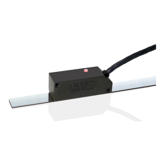
Magnetic Absolute Length Measuring System with 0.01mm Resolution
Absolute measuring
Direct contact free measurement
Up to 10 m measuring length (20 m on request)
Resolution 0.01 mm
Changes of position are also recognized without voltage –
no calibration necessary
Automatically recognition of too big distance between sensor and
magnetic tape (LED indicator)
Additional incremental signals for dynamic drive mechanism available
Advertisement
Table of Contents

Related Manuals for ELGO Electronic EMAX2 Series


Summary of Contents for ELGO Electronic EMAX2 Series
- Page 1 Operation manual SERIES EMAX2 Magnetic Absolute Length Measuring System with 0.01mm Resolution Absolute measuring Direct contact free measurement Up to 10 m measuring length (20 m on request) Resolution 0.01 mm Changes of position are also recognized without voltage – no calibration necessary Automatically recognition of too big distance between sensor and magnetic tape (LED indicator)
-
Page 2: Table Of Contents
Contents General ..........................3 Information Operation Manual ....................3 Explanation of Symbols ......................3 Statement of Warranties ......................4 Demounting and Disposal ..................... 4 Product Features ........................ 5 Functional Principle ...................... -
Page 3: General
General General 1.1 Information Operation Manual The manual contains important information regarding the handling of the indicator. For your own safety please note all safety warnings and instructions. Precondition for safe operation is the compliance with the specified safety and handling instructions. Moreover, observe the existing local accident prevention regulation and general safety rules. -
Page 4: Statement Of Warranties
General Tips and recommendations: NOTE! Here you can see highlights, useful tips, information and recommendations for efficient and trouble-free operation. 1.3 Statement of Warranties The warranty conditions are in a separate document in the sales documents. Guarantee The producer guarantees the functional capability of the process engineering and the selected parameter. The period of warranty is one year and begins with the date of delivery. -
Page 5: Product Features
Product Features 2 Product Features The series EMAX2 is an absolute length measuring system. Sensor and translator and interpolation unit are together in one housing. The magnetic tape of series EMAB is paste up to a plain area. The EMAX2 can be mounted with a max. - Page 6 Picture 2: Coding...
-
Page 7: Safety
Safety 3 Safety 3.1 General Cause of Risks This chapter gives an overview about all important safety aspects to guarantee an optimal protection of employees. Non-observance of the instructions mentioned in this operation manual can result in hazardous situations. 3.2 Personal Protective Equipment Employees should wear protective clothing during installation of the device to minimize the risk of accidents. -
Page 8: Technical Data
Technical Data 4 Technical Data Mechanical Data Measuring principle absolute Repeat accuracy +/‐ 1 increment +/‐ (150 + 20 x L) (type design. 010) System accuracy in µm at 20 °C +/‐ (50 + 20 x L) (type design. F10) L = effective measuring length Distance from the sensor to max. 1.5 mm, 2.0 mm with reduced accuracy magnetic tape Basic pole pitch 5 mm Sensor housing material zinc diecasting Sensor: L x W x H = 75 x 24 x 26 mm Housing dimensions Sensor with guide carriage: L x B x H = 100 x 34 x 48 mm Meas. length 10 m: AB20‐50‐10‐2‐R‐11 Necessary magnetic tape Meas. length 20 m: AB20‐50‐10‐2‐R‐12 EMAX : up to 10 m Max. measuring length EMAL : up to 20 m Cable connection open cable end EMAX2: ca. 100 g without cable Weight cable: ca. 60 g per meter Ambient Temperature Storage temperature ‐25… +85 °C ‐10… +70 °C ... -
Page 9: Dimensions Emax2
Technical Data 4.1 Dimensions EMAX2 Seitenansicht * The amount of decode switches is depending on the interface Front view Rear view 24,00 24,00 15,00 2,00 0,93 10,00... -
Page 10: Dimensions Emax2 With Fw2080
Technical Data 4.2 Dimensions EMAX2 with FW2080 Side view 16,50 Ø4,50 83,50 Ø8,00 Top view 95,00 83,50 16,50 10,00 5,00 80,00 R 4,00 Ø3,50 Ø6,00 Front view 8,00 20,00 13,00 22,00 25,00 11,50... -
Page 11: Transport And Storage
Transport and Storage 5 Transport and Storage Safety Instructions for Transport, Unpacking and Loading ATTENTION! Professional transport only. Do not throw, hit or fold the package. 5.2 Handling of Packaging Material Adverts for proper disposal refer to chapter demounting and disposal. 5.3 Check of Transport Examine delivery immediately after receiving for completeness and transport damages. -
Page 12: Installation / Commissioning
Installation / Commissioning 6 Installation / Commissioning Mounting of the Sensor Head NOTE! The distance between sensor and tape is monitored and indicated by the LED on the sensor. ->distance OK =LED glow green ->distance not OK =LED glow red For mounting the sensor head two 3M screws have to be used Tolerances for distance and angle must be observed. -
Page 13: Pin Connections
Installation / Commissioning 6.2 Pin Connections Signal Function RS422 Function RS422 Option RS232 Option RS232 Option RS232 cable (420, A20) (420, A20) (230) (230) (230) Incremental HTL Incremental HTL Incremental TTL white 0 V / GND 0 V / GND 0 V / GND 0 V / GND 0 V / GND... -
Page 14: Interfaces
Installation / Commissioning Signal cable 8-pin M16 cable box with ELGO standard SSI- 154500003 interface ( M8F0 1 white 0 V / GND 2 brown 3 yellow Data (+) 4 orange Data (-) 5 green Clock (+) 6 violet Clock (-) 7 (n.c.) 8 (n.c.) 6.3 Interfaces... -
Page 15: Rs422 Adressable Version (Option A20)
Installation / Commissioning 6.3.2 RS422 Adressable Version (Option A20) Protocol of an addressable EMAX2 version 1.4 The device address can be adjusted by a decoding switch which is located behind Position Address a protection cap on the top of the sensor housing: Terminating Address Baud rate... - Page 16 Installation / Commissioning Interrogation of the address of an EMAX2: Connect always only a single EMAX2 to be interrogated via RS422/RS232 converter to COM port of a PC. Message to the EMAX: 0x02 0x05 0x05 0x0c 0x03 address request check Answer of the EMAX: 0x02 0xff...
-
Page 17: Connection To A Rs422 Master
Installation / Commissioning 6.3.3 Connection to a RS422 Master Colour Function Green Violet Yellow Orange Brown +24VDC White 0 V (GND) 6.3.4 SSI - (Option SB0 or SG0) Principle of the function: If the clock is not interrupted for the time Tm-T/2 (output of further 25 periods), the shift register clocks once again the same data value (error recognition in evaluation). -
Page 18: Canopen - (Option Ca0)
Installation / Commissioning 6.3.5 CANopen - (Option CA0) Interface / Protocol: As standard the EMAX2 measuring system is equipped with a CANopen standard interface DS406, when ordering option CA0. The following identifiers are given: CAN - Identifier (4 Byte telegram) 180 (16) = Identifier First 4 bytes... -
Page 19: Can Basic Elgo - (Option Cn0)
Installation / Commissioning 6.3.6 CAN BASIC ELGO - (Option CN0) Interface / Protocol: On request the EMAX2 measuring system is equipped with a CAN interface with ELGO CAN standard protocol. The following identifiers are given: 80 (16) + EMAX address = Identifier to request the absolute position 10 (16) + position of decoding switch = Identifier contains absolute position of the... - Page 20 Installation / Commissioning A/B – Incremental Output (Option HXXX or TXXX) Optionally two 90° phase shifted square wave channels are available (shaft encoder compatible) with HTL-or TTL-output level (push/pull) The EMAX resolution (at 4 edge triggering) can have the following amounts: 2.5 μm;...
-
Page 21: Sine Cosine Incremental Signals (Option Sc50)
Installation / Commissioning 6.3.7 Sine Cosine Incremental Signals (Option SC50) Optionally Sine Cosine signals with 1 Vpp are available. (push/pull output, short circuit resistant) Example “emulation switching” Parameter Description min. typ. max. Unit Um (sin), Medium voltage Um (cos) sin – sin Amplitude cos - cos (sin –... -
Page 22: Terminating Impedance
Installation / Commissioning 6.3.8 Terminating Impedance As standard the interfaces CANopen, CAN BASIC ELGO (CN0) and RS422 are supplied with a termination impedance of 120 Ω inside of the interface input. The termination impedance can be deactivated with the S3 switch. The SSI interface is also supplied with an integrated termination impedance. When using option V (encapsulated –... -
Page 23: Options
Options 7 Options 7.1 Magnetic Tape The magnetic tape consists of 3 components (see picture 5) • a magnetized flexible rubber tape (pos. 3), which is connected factory made with a • steel band (pos. 5) and a • covering band (pos. 1) , which is intended for the protection of the rubber tape. •... -
Page 24: Processing Note For Sticking
Options 7.1.2 Processing Note for Sticking The provided sticky tapes stick well on clean, dry and plain surfaces. The worse the pollution at the place of instalment, the better the sticky tapes should be. A surface roughness of R <= 3.2 (R <= 25 / N8) is recommendable. -
Page 25: Operation
Operation / Interference 8 Operation 8.1 Offset After the installation of the magnetic tape and the measuring system (sensor head), a value is transmit by the interface. Because this value does not conform to the machine zero point, an offset should to be deposited at the controller side. -
Page 26: Electrical Interference Suppression
Interference / Maintenance Electrical Interference Suppression The shield of signal output cable should only be connected one-way to the following electrical device. Signal wires should be installed separately from load power lines and with a safe distance of at least 0.5 m to capacitive and inductive interferences such as contactors, relays, motors, switching power supplies, timed controllers. -
Page 27: Type Designation Emax2
Type Designation 11 Type Designation EMAX2 For ordering please use the following reference code: Sensor head EMAX _ _ _ _ _ _ _ _ _ _ _ _ _ _ _ _ _ _ _ _ _ _ _ _ _ _ Note: A A B B B C C C D D D E E E E F G G G G H I J J J J Please use description EMAL , if a... - Page 28 Type Designation Examples: EMAX 0 0 0 1 5 0 1 0 S B 0 - - - - - - - - - - - - - - - A A B B B C C C D D D E E E E F G G G G H I J J J J EMAX2 with SSI binary interface, 25 bit and 1.5 m cable EMAX 0 0 0 1 5 0 1 0 S B 0 - - - - - M 8 F 0 - - - - - -...
-
Page 29: Accessories
Accessories 12 Accessories Magnetic tape AB20-50-20-2-R-11: Art. No.: 731000110 Technical Data Operating temperature - 20° up to + 85 °C Stock temperature - 40° up to + 95 °C Humidity max 80 % (non-condensing) Thermal expansion ΔL α ϑ ΔL = L x x Δ... -
Page 30: Index
Index 13 Index A M Absolute trace ............ 5 Magnetic influences .......... 22 Absolute value ............ 5 Mechanical data ............. 7 B O Basic pole pitch ............ 7 Offset .............. 24 Binary code ............ 16 Ordering ............... 26 C P CAN‐Identifier ............ 17 Periodic and random deviation ...... 7 CANopen .............. 17 Pole searcher film .......... 11 Coding .............. 5 Position‐request ........... 14 Power supply............ 7 D Product features ............ 5 Decoding switch ........... 14 Protection cap ............ 16 Disposal .............. 4 ... - Page 31 Document History Document History Rev. Date Author Changes 11.04.2011 Document translated 19.04.2013 Description of LED function Document- Nr.: 799000616 / Rev.1 Document- Name: EMAX2-000-E_16-13 Subject to change - © 2011 ELGO Electronic GmbH & Co. KG...
Need help?
Do you have a question about the EMAX2 Series and is the answer not in the manual?
Questions and answers