Table of Contents
Advertisement
Quick Links
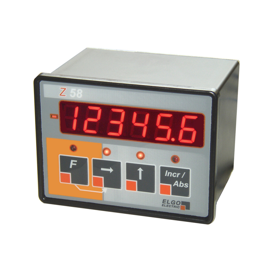
Z58-6XX SERIES
6 Digits Universal Position Indicator for
incremental or absolute encoders
•
connectable to inkremental- or
absolute encoders (FMAX, FEMAX, EMAX)
•
approved standard functions
(e.g. pulse scaling, multi-edge-counter,
Inch/mm-switch over)
•
three external inputs (+ 24 V)
•
serial interface RS-232
•
analog input 0... 10 V or 0... 20 mA (option) analog output 0... 10 V / 0
(4)...20 mA (option)
•
Optionally 2 shutter-relay-outputs (option)
Advertisement
Table of Contents

Related Manuals for ELGO Electronic Z58-6 Series


Summary of Contents for ELGO Electronic Z58-6 Series
- Page 1 Z58-6XX SERIES 6 Digits Universal Position Indicator for incremental or absolute encoders • connectable to inkremental- or absolute encoders (FMAX, FEMAX, EMAX) • approved standard functions (e.g. pulse scaling, multi-edge-counter, Inch/mm-switch over) • three external inputs (+ 24 V) • serial interface RS-232 •...
-
Page 2: Table Of Contents
1. GENERAL FEATURES 2. DISPLAY-WINDOWS, MONITOR-LEDS AND KEYPAD 3. OPERATION MODES 4. LIST OF PARAMETERS 5. FUNCTIONS OF PARAMETERS 6. FUNCTIONS OF THE KEYPAD AND OF EXTERNAL INPUTS 6.1 Reset 6.2 Absolute/Incremental mode 6.3 Additional tool-offset 6.4 Set to datum-value 7. -
Page 3: General Features
1. General features • Power supply 24 VDC (standard) • 115/230 VAC with external power pack NG13.0 • Panel- or built-on housing available • Cut out for panel 93 x 67 mm (w x h) • Install depth 73 mm (110 mm with D-SUB-Connector) •... -
Page 4: Display-Windows, Monitor-Leds And Keypad
2. Display-windows, Monitor-LEDs and keypad Sign Status Relays 2 (Option) shines if counting shines if activated value is negative Tool Offset shines if activated Status Relays 1 (Option) shines if activated Incr/Abs shines if Incr is activated Set to datum-value Example with full configuration Tool offset * Entire/Relative measurement switch over* * Only in normal mode... -
Page 5: List Of Parameters
4. List of parameters To lock the programming-level of the menu, please press at the same time, for 3 seconds… Buttons F + Incr/Abs and it appears on Display Incr/Abs – Button Step up the Number of Parameter. With ▲ - and ►... -
Page 6: Functions Of Parameters
5. Functions of parameters P00 = Reserved for tests P01 = Switch over of counting direction P02 = Empty P03 = Selection of decimal point P04 = Activate or deactivate Power down memory here P06 = Select multi-edge-counter here (x 1, x 2 x or x 4) P07 = Selection of measuring-system: The connected encoder system must be selected here! 0 = Incremental signals A/B/Z... -
Page 7: Functions Of The Keypad And Of External Inputs
6. Functions of the keypad and of external inputs 6.1 Reset For setting the actual value to zero: Use the external input ST2/Pin6, and connect resp. close it for a short time to + 24 V to reset the actual value. Please note: The external input is a static input and is active, when it’s connected with + 24 V. -
Page 8: Teaching Procedure
7. Teaching procedure (only when using an ELGO FMAX absolute linear encoder) If an ELGO-FMAX encoder is connected, the following steps must be done, to calibrate and modulate the sensor with Z58: 1. Press for 3 sec., at the same time - in normal operation mode - Buttons - ►... -
Page 9: List Of Most Important Key-Functions
9. List of most important key-functions Normal mode: Datum value = at the same time For a short time Setting reference For 3 seconds Change reference value (P09) Back to normal Operation mode = press for 3 sec. Tool offset = Undo = Abs./Incr = switch over between... -
Page 10: Serial Interface
10. Serial Interface Technology: Standard RS232 Data format: Baud rate = 9600 8 Data bits, 1 Stopbit, no parity Z58 answers only on request of the PC 10.1 Commands Readout the actual value: Command: STX ´i´ ETX Example: 02h 69h 03h Answer: e.g.. -
Page 11: Pin-Assignment
12. Pin-Assignment Connector ST5 Connector ST4 Connector ST2 Connector ST1 Connector ST3 Example rear with full configuration Inverted signals are marked with ’ Connector ST1 Connector ST3 (standard encoders): (absolute signals, relays, analog-output): 1: GND (output) 1: Screen/shield/PE 2: + 5 VDC/24 VDC (output) 2: GND (Encoder supply) -
Page 12: Pin-Assigment Z58-654
12.1 Pin-Assigment Z58-654 Addional sheet for 115 or 230 VAC power supply Please Note! The following functions are not available with the AC-Variant! 1. Encoder Systems 2 = A/A’ B/B’ Z/Z’ 24 VDC Encoder supply, 5 V-TTL (PNP)- 100 KHz 3 = A/A’... -
Page 13: Technical Specifications
13. Technical specifications 1) Position Indicator Z58.6XX.024 24 VDC - Version Power voltage 24 VDC +/- 20 % Consumption max. 70 mA (without measuring system) 2) 115 or 230 VAC supply If there is only an AC-Voltage is available (115/230 VAC), please use the external ELGO power pack Type NG13.0. -
Page 14: Dimensions
14. Dimensions 14.1 Measurements of the panel housing (in mm) 91,5 Install depth with screw terminals = 78 mm Install depth with SUB-D connector = 115 mm 64,5... -
Page 15: Measurements Of The Built On Housing (Option Ag)
14.2 Measurements of the built on housing (Option AG) (in mm) Screw length max. 15 mm Side view Side view Depth inclusive power plug: 160 mm... -
Page 16: Type Designation
15. Type designation Z58 - 6XX - XXX - X - XXXXXXX Position Indicator Universal single axis SN-Number 600 = Standard 601 = First special version 602 = Second special version etc. Power supply voltage 024 = 24 VDC (+/- 20 %) Signal inputs 1 = A/B/Z 24 VDC Encoder supply, 24 V- output level (PNP) - 100 KHz 2 = A/A’... -
Page 17: Liability Exclusion / Guarantee
The guarantee period is one calendar year from the date of delivery and includes the delivered unit with all components. ELGO Electronic GmbH & Co. KG will at its option replace or repair without charge defects at the unit or the included parts, verifiable caused by faulty manufac- turing and/or material in spite of proper handling and compliance to the instruction manual.
Need help?
Do you have a question about the Z58-6 Series and is the answer not in the manual?
Questions and answers