Table of Contents
Advertisement
Operation manual
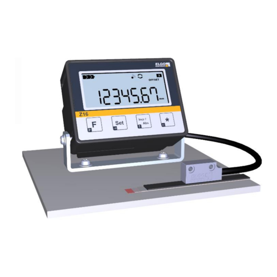
SERIES IZ16E-000
Battery-powered Length Measuring System
Large 7-digit LCD-Display, digit height 14 mm
With sign and special signs
Battery status indicator
„° "-symbol for angle measurement
Fraction display in inch mode
Internal or external battery case
Resolution up to 0.01 mm
Display in inch mode „0.001 Inch"
Tool-offset
Simple installation (Snap-In-Housing)
Option built-on enclosure with mounting holder
Advertisement
Table of Contents

Related Manuals for ELGO Electronic IZ16E-000 Series


Summary of Contents for ELGO Electronic IZ16E-000 Series
- Page 1 Operation manual SERIES IZ16E-000 Battery-powered Length Measuring System Large 7-digit LCD-Display, digit height 14 mm With sign and special signs Battery status indicator „° “-symbol for angle measurement Fraction display in inch mode Internal or external battery case ...
-
Page 2: Table Of Contents
Content Content General ......................4 Information Operation Manual .................. 4 Explanation of Symbols ..................... 4 Statement of Warranties .................... 5 Demounting and Disposal ..................5 Safety ......................... 6 General Cause of Risks ..................... 6 Personal Protective Equipment..................6 Conventional Use ....................7 Transport and Storage .................. - Page 3 General Content 9.3.1 Installation IZ16E-000-x-xx.x-x in the front panel ..............27 9.3.2 Installation IZ16E-000-x-xx.x-x with a mounting angle ............28 9.3.3 Installation IZ16E-000-8-xx.x-1-AG .................. 29 Activating the device ....................30 Description of mounting / Installation of the magnetic sensor ........30 Installation of the magnetic tape ................
-
Page 4: General
1 General 1.1 Information Operation Manual The manual contains important information regarding the handling of the indicator. For Your own safety please note all safety warnings and instructions. Precondition for safe operation is the compliance with the specified safety and handling instructions. Moreover, observe the existing local accident prevention regulation and general safety rules. -
Page 5: Statement Of Warranties
General DANGER! ...marks perilous situations by electricity. By non-observance of the safety instructions the possibilities of death or severe injuries exist. The operations have to be carried out only by an electrician. Tips and recommendations: Note! Here you can see Highlights, useful tips, information and recommendations for efficient and trouble-free operation. -
Page 6: Safety
In case of damage caused by failure of these operating instructions the warranty expires. ELGO Electronic GmbH & Co. KG and its subsidiaries are not liable for any damage to persons, property or asset caused by defective material on the device and / or its associated. -
Page 7: Conventional Use
2.3 Conventional Use The indicator IZ16 is for the limited purpose as described in this manual: The IZ16E ELGO length measurement system is constructed for measuring and displaying distances. CAUTION! Danger through non-conventional use! Non-intended use and non-observance of this operation manual can lead to dangerous situations. -
Page 8: Transport And Storage
Transport and Storage Product Features 3 Transport and Storage 3.1 Safety instructions for transport, unpacking and loading ATTENTION! Professional transport only. Do not throw, hit or fold the package. 3.2 Handling of Packaging Material Adverts for proper disposal refer to 1.4. 3.3 Check of Transport Examine delivery immediately after receiving for completeness and transport damages. -
Page 9: Product Features
Applications 4 Product Features The length measuring system IZ16E is a combination of an external magnetic sensor that is connected via a drag-chain suitable cable to the display device. For the measurement a coded magnetic tape, which provides the sensor with the necessary information (current position), is glued along the distance that has to be measured. -
Page 10: Applications
Applications 5 Applications 5.1 Magnetic measurement 5.1.1 Direct Distance Measurement The magnetic tape is glued on a solid ground (e.g. machine base) along the measuring distance. Example 1) Indicator [mm], resolution 0.01mm P02=0 / P03=2 / P08=1,0000 Example 2) Indicator [m], resolution 0.001m ... -
Page 11: Measurement With Pole Ring
Technical Data 5.2 Measurement with pole ring 5.2.1 Indirect Distance Measurement A pole ring / magnet wheel is mounted on a rotating axis (e.g. motor shaft). Example: Spindle drive with gear box, the pole ring at the engine, indicator [mm], resolution 0.01mm, pole ring (D=48mm) with 60 poles per ... -
Page 12: Technical Data
Technical Data 6 Technical Data 6.1 Position Indicator IZ16E 6.1.1 Identification The label is helpful for the identification of the unit. It is located on the housing of the position indicator. It provides information about the exact type designation (= order reference; see model code, section 7) with the corresponding item number. -
Page 13: Version Iz16E-000-1-Xx,X-0
Technical Data 6.1.2.2 Version IZ16E-000-1-xx,x-0 6.1.2.3 Version IZ16E-000-6-xx,x-0... -
Page 14: Version Iz16E-000-1-Xx,X-1
6.1.2.4 Version IZ16E-000-1-xx,x-1 6.1.2.5 Version IZ16E-000-6-xx,x-1... -
Page 15: Version Iz16E-000-8-Xx,X-1-Ag
Technical Data Technical Data 6.1.2.6 Version IZ16E-000-8-xx,x-1-AG The mounting holder is adjustable in the angle, allows also lateral adjustment and can be mounted above or below. -
Page 16: Technical Data Iz16E
Technical Data 6.1.3 Technical Data IZ16E Position Indicator IZ16E 7 decades (digit height 14mm) LCD-Display With sign, battery status and measurement units Measuring unit mm, m, Inch or ° Perspective 12 o’clock Keyboard Foil with softkeys Measuring principle Magnetic, theoretically absolute Measurement linear or rotative Power supply... -
Page 17: Power Supply / Battery Change
Technical Data 6.1.4 Power supply / Battery change ADVERT For a long operating time, the use of commercially branded batteries is recommended. If all the battery icons on the LCD-Display are extinguished (see also section Fehler! Verweisquelle konnte nicht gefunden werden.), a battery change should be made as soon as possible. -
Page 18: Magnetic Sensor Ms20.25
Technical Data 6.2 Magnetic Sensor MS 20.25 6.2.1 Dimensions of the Magnetic Sensor 6.2.2 Technical Data of the Magnetic Sensor Magnetic Sensor MS20.25 Pole length 2.5 mm Sensor cable length 0.1 m … max. 2.0 m Sensor cable Drag-chain suitable, 6-wires, twisted pairs and double shielded Housing Zinc die cast Protection class... -
Page 19: Magnetic Tape Mb20-25
6.3 Magnetic Tape MB20-25 The magnetic tape contains the necessary digital information needed for linear length measurement using an ELGO length measuring systems. Basically a distinction is made between incremental and absolute measuring. The incremental measuring system consists of reading electronic, which is scanning north and south poles on the magnetic tape and is creating a Sine and Cosine signal. -
Page 20: Handling
Technical Data 6.3.2 Handling In order to avoid tension in the tape, it must not be stretched, compressed or twisted. It should be stored with the magnetized plastic tape to the outside (see Figure 2), the minimum bending radius must be noted here (see section 6.3.5). Magnetized Plastic tape Steel tape... -
Page 21: Technical Data Magnetic Tape
Type Designation / Variants Technical Data 6.3.5 Technical Data Magnetic Tape Magnetic tape MB20-25-10-1-R Coding Incremental, single track Pole length 2.5mm Operating temperature 0 °C … +50 °C Short term: -10 °C … +60 °C Storage temperature Medium term: 0 °C …+40 °C Long term: +18 °C Relative humidity max. -
Page 22: Type Designation
7 Type Designation IZ16E - 000 - 1 - 01.0 - 0 - X Series / Type: IZ16E: Position Indicator with external Sensor Version No.: 000 = Standard Supply: 1 = integrated battery case with cover (1x Type C / LR14 / Baby) 6 = pluggable screw clamps (2-pole. - Page 23 Type Designation / Variants 7.1 Available Variants Order Code Description IZ16E-000-1-xx,x-0 Integrated battery holder, fixed sensor cable outlet IZ16E-000-1-xx,x-0-CAP Integrated battery holder, fixed sensor cable outlet, with backup capacitor IZ16E-000-6-xx,x-0 Screw clamps, fixed sensor cable outlet IZ16E-000-6-xx,x-0-CAP Screw clamps, fixed sensor cable outlet with backup capacitor (only for 1,5V) IZ16E-000-6-xx,x-0-24V* Screw clamps, fixed sensor cable outlet with 24V- power supply* IZ16E-000-1-xx,x-1...
-
Page 24: Type Designation Magnetic Tape
Type Designation Magnetic Tape / Variants Installation and Initial Start-up 8 Type Designation Magnetic Tape 8.1 Available Variants Order Code Description MB20-25-10-1-R Magnetic tape in the standard package with cover band and adhesive tape MB20-25-10-1-R-B Without tape on the back side/ with enclosed adhesive tape MB20-25-10-1-R-C With tape on the back side/ without cover band MB20-25-10-1-R-D... -
Page 25: Installation And Initial Start-Up
In case of damage caused by failure observing the installation instructions, the warranty will be invalidated. The ELGO Electronic GmbH & Co. KG and the subsidiaries are not liable for injury to persons, property or financial loss, which can by faulty material on the device and / or incurred by the related components. -
Page 26: Interferences
Installation and Initial Start-up 9.2 Interferences If errors cannot be corrected with the following instructions please contact the manufacturer (see last page). NOTE Device, connection cables and signal cables must not be installed directly next to interference, which have strong inductive or capacitive interference or strong electrostatic fields! External interference can be avoided by a suitable cable routing. -
Page 27: Mounting Description / Installation Of The Indicator
Installation and Initial Start-up 9.3 Mounting description / Installation of the Indicator 9.3.1 Installation IZ16E-000-x-xx.x-x in the front panel The mounting of the device in the front panel is achieved by four slide clips (“Snap-In Mounting“). For this purpose no tools or special tools are needed. The IZ16E comes with a separate seal. -
Page 28: Installation Iz16E-000-X-Xx.x-X With A Mounting Angle
9.3.2 Installation IZ16E-000-x-xx.x-x with a mounting angle The mounting angle is available in the accessory, with reference to part 11.1. The detent of the device in the mounting angle is achieved by four slide clips (“Snap-In Mounting“). For this purpose no tools or special tools are needed. The IZ16E is delivered with a separate seal. The mounting of the seal is necessary for the correct hold in the mounting angle. -
Page 29: Installation Iz16E-000-8-Xx.x-1-Ag
Installation and Initial Start-up 9.3.3 Installation IZ16E-000-8-xx.x-1-AG Step 1: mounting the battery Step 2: fixing the mounting clamp Step 3: screw & underlay right Step 4: screw & underlay left... -
Page 30: Activating The Device
Installation and Initial Start-up Installation and Initial Start-up 9.4 Activating the device After starting the operating voltage (e.g. insert the battery) the device starts automatically. 9.5 Description of mounting / Installation of the magnetic sensor With the use of two screws type M3, the magnetic sensor can be mounted with the help of the fastening bores. (see chapter 6.2.1). -
Page 31: Installation Of The Magnetic Tape
Installation und Initial Start-up 9.6 Installation of the magnetic tape NOTE External Magnetic Fields The influence of the magnetic tape by magnetic fields is to be avoided! The magnetic tape should not come into direct contact with other magnetic fields (e.g. permanent magnets, holding magnets, electromagnets, magnetic stands)! Irreparable damage is likely to affect either the accuracy or even the function! 9.6.1 Processing note for the bonding... -
Page 32: Cutting And Sticking
Structure and Function 9.6.2 Cutting and Sticking Before starting the gluing, the magnetic tape and the cover band need to be cut to the exact length: Length of the magnetic tape = Measuring length + 100 mm Length of the cover tape = Measuring length + 100 mm + Overlap* ADVERT In an unprotected environment, there is the danger that the cover band... -
Page 33: Structure And Function
Structure and Function 10 Structure and Function The operation of the device is divided into the parameter level (see section 10.3), the operator level (see section 10.5) and the initialization level. All operating parameters can be put in through the parameter level (see section 10.3.6). At the operator level the basic functions are available (depending on the software version). -
Page 34: Key-Overview
10.2 Key-Overview The function of the keys in the parameter level is shown on the button in the dark box on the left below the function at the operating level is shown in the bright field size: Keys Function at the operating level (see 10.5) Function at the parameter level (see 10.3) Base-keys for keyboard shortcuts Parameter level enable/disable... -
Page 35: Parameter Level
Structure and Function Structure and Function 10.3 Parameter Level Adjusting settings 10.3.1 Activate the Parameter Level Hold it for about 3 seconds / then press each 1x The parameter level is activated with this key. After about 3 seconds the display shows „P01“for the first parameter. -
Page 36: Parameter List
10.3.6 Parameter list Parameter: Description: Default: P01: A System configuration: A = 0: Counting positively A = 1: Counting negatively P02: A Display mode (affect only the display of symbols!) A = 0: mm-Mode / Display symbol „ mm “ A = 1: Inch-Mode / Display symbol „... -
Page 37: Initialization Level
Structure and Function 10.4 Initialization Level Resetting the parameter and calibration 10.4.1 Calibration ADVERT The calibration is already factory-made and must not run again normally. In a few cases a re-calibration of the device after the installation can achieve an advancement of the accuracy, because with a re- calibration the additional mounting factors (angular deviation, parallelism, etc.) are included. -
Page 38: Function At The Operator Level
Structure and Function 10.5 Function at the Operator Level Working with the device 10.5.1 Actual Value to Reference Keys 1x press at the same time With this shortcut, the actual value (display value) on the adjustable reference value is set (in absolute mode only possible when the offset is not enabled). -
Page 39: Fraction Display In The Inch-Mode
Structure and Function Accessories 10.5.5 Fraction Display in the Inch-Mode 1x pressed With this key the display can be changed in the Inch-mode (parameter P02 = 1) as follows: 1x key pressed: Display Inch- fraction display 1/64 Inch 1x key pressed: Display Inch- fraction display 1/32 Inch 1x key pressed: Display Inch- fraction display 1/16 Inch... -
Page 40: Accessories
Accessories 11 Accessories 11.1 Mounting angle Order Code Description mounting angle IZ16E Steel sheet, 2mm, zinced... -
Page 41: Battery Holder
Accessories 11.2 Battery Holder Assembly version: Open version: Order Code Description battery holder-set 1xC Assembly inclusive battery holder (Type C), battery and 2x cable shoes battery holder-set 1xC Open inclusive battery holder (Type C), battery and 2x cable shoes... -
Page 42: Cover Band Individual
Accessories 11.3 Cover Band individual Drawings see section 6.3.4 . Order Code Description SB-20-10-01-14404 (AB10) Cover band, 10mm wide, single with double-sided adhesive tape 11.4 Aluminum Guiding Rail Order Code Description FS-20.25-xxxx Aluminium rail with pre-glued magnetic tape (xxxx = Length in mm) MB20-25-10-1-R FS-xxxx Aluminium rail with 2 slots for embedding a 10 mm or a 20 mm wide... -
Page 43: Magnetic Tape End Cap
Interferences 11.6 Magnetic Tape End Cap The magnetic tape end cap is offering the optimal protection against the peeling of the magnetic tape/ cover band. (see chapter 9.6.2) Furthermore, in the working area the risk of injury by any existing sharp edges is minimized with the end caps. Order Code Description MB End Cap 10mm / single... -
Page 44: Interferences
Maintenance / Cleaning 12 Interferences The following chapters describe possible causes for malfunction and the instructions to correct them. 12.1 Safety WARNING! Risk of injury by improper disposal! Improper disposal can lead to severe disturbance to persons or property. Therefore: Any work to rectify the fault may be performed only by ... -
Page 45: Maintenance
13 Maintenance The device is maintenance-free. WARNING! Hazard due to improper maintenance! Improper maintenance can result to serious personal injury or property damage. Therefore: Maintenance work must be performed only by qualified and authorized by the operator and instructed personnel. 14 Cleaning WARNING! The system should be cleaned with damp cloth, do not use aggressive... -
Page 46: Index
Index 15 Index Installation Magnetic Sensor ........28 Interferences ............26 Aktivierung .............. 30 Aluminum Guiding Rail ..........42 Angle Measurement.......... 10, 11 Magnetic Tape ............19 Applications............. 10 Montage Magnetsensor .......... 30 Calibration ............... 37 Operational Environment ........25 Cause of Risks ............ -
Page 47: Document History
Upgrading: mounting description 9.3 Adjustment: explanation of symbols 1.2 21.06.10 Upgrading: repeatability 6.2.2 20.11.19 Cable option 1 in Chapter 7 corrected Document No.: 799000575 / Rev. 4 Document Name: IZ16E-000-MA-E_47-19 Subject to Change - © 2019 ELGO Electronic GmbH & Co. KG...
Need help?
Do you have a question about the IZ16E-000 Series and is the answer not in the manual?
Questions and answers