Table of Contents
Advertisement
Quick Links
799000710 / Rev. 4 / 2018-03-22
Translation of the original operating manual
Operating Manual
SERIE EMAX-HI
Magnetic Absolute Length Measuring System
High resolution - 1µm
For highly dynamic controls
8 m measuring length
Automatic distance detection via LED
Available Interfaces: SSI, CANopen or RS422
On request: BISS-C or CAN BASIC ELGO
Optionally, incremental square wave signals (A, B)
or 1 Vss sine-cosine for dynamic movement control
Advertisement
Table of Contents

Related Manuals for ELGO Electronic EMAX-HI Series


Summary of Contents for ELGO Electronic EMAX-HI Series
- Page 1 799000710 / Rev. 4 / 2018-03-22 Translation of the original operating manual Operating Manual SERIE EMAX-HI Magnetic Absolute Length Measuring System High resolution - 1µm For highly dynamic controls 8 m measuring length Automatic distance detection via LED ...
- Page 2 +49 (0) 7731 9339 – 0 +49 (0) 7731 2 13 11 info@elgo.de Document- No. 799000710 Document - Name EMAX-HI-00-MA-E_12-18 Document- Revision Rev. 4 Issue Date 2018-03-22 Copyright © 2018, ELGO Electronic GmbH & Co. KG - 2 -...
-
Page 3: Table Of Contents
Contents 1 Contents Contents ..................... 3 General, Safety, Transport and Storage ............ 4 Information Operating Manual ................... 4 Explanation of Symbols ...................... 4 Statement of Warranties ..................... 5 Demounting and Disposal ....................5 General Causes of Risk ..................... 5 Personal Protective Equipment .................... 5 Conventional Use ...................... -
Page 4: General, Safety, Transport And Storage
General, Safety, Transport and Storage 2 General, Safety, Transport and Storage Information Operating Manual This manual contains important information regarding the handling of the device. For your own safety and operational safety, please ob- serve all safety warnings and instructions. Precondition for safe operation is the compliance with the specified safety and handling instructions. -
Page 5: Statement Of Warranties
General, Safety, Transport and Storage Statement of Warranties The statement of warranties is enclosed separately in the sales documents. Guarantee: The producer guarantees the functional capability of the process engineering and the selected parameters. The period of warranty is one year and begins with the date of delivery. -
Page 6: Conventional Use
General, Safety, Transport and Storage Conventional Use The product described in this manual was developed to execute safety-related functions as a part of an entire assembly or machine. It is the responsibility of the manufacturer of a machine or installation to ensure the proper functioning of the system. The ELGO-device is only conceived for the conventional use described in this manual. -
Page 7: Product Features
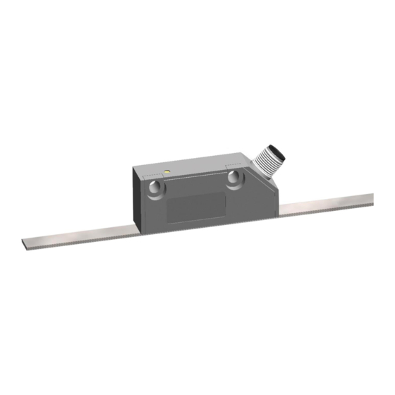
Product Features 3 Product Features EMAX-HI is a magnetic length measuring system. Sensor and translator are integrated in one housing. The mag- netic tape is attached to a flat surface using the adhesive tape included in the delivery. EMAX-HI can be installed at a distance of up to 0.5mm from the magnetic tape (without cover tape). -
Page 8: Technical Data
Technical Data 4 Technical Data Identification The type label serves for the identification of the unit. It is located on the housing of the sensor and gives the exact type designation (=order reference, see type designation) with the corresponding part number. Furthermore, the type label contains a unique, traceable device number. -
Page 9: Technical Data Sensor
Technical Data Technical Data Sensor EMAX-HI (standard version) Mechanical Data Measuring principle absolute Repeat accuracy ±1 Increment System accuracy in at 20° C ±(10 µm + 20 µm x L[m]) L = measuring length in meters Distance sensor - magnetic tape max. -
Page 10: Technical Data Magnetic Tape
Technical Data Technical Data Magnetic Tape The magnetic tape consists of two components: The actual magnetic tape which carries the position information A mechanical stainless steel back iron Magnetic Tape AB20-10-10-2-R-11 Coding absolute, two tracks system Pole pitch 1 mm Operation temperature installed -20 …... -
Page 11: Installation And First Start-Up
Installation and First Start-Up 5 Installation and First Start-Up CAUTION Please read the operating manual carefully before using the device! Strictly observe the Instal- lation instructions! In case of damage caused by failure to observe this operating manual, the warranty expires. ELGO is not liable for any secondary damage and for damage to persons, property or assets. -
Page 12: Description Installation / Installation Of The Indicator
Installation and First Start-Up Description installation / Installation of the indicator 5.2.1 Mounting Tolerance NOTE! Pay attention to correct distance sensor / magnetic tape 0,1 mm…max. 0,5 mm! The LED- Indicator on the sensor housing flashs red, if this distance is exceeded. The direction arrow have to point in the same direction by the assembly. -
Page 13: Description Installation / Mounting Of The Magnetic Tape
Installation and First Start-Up Description installation / Mounting of the Magnetic Tape NOTE: External Magnetic Fields The magnetic tape must not be influenced by external magnetic fields! The magnetic tape must not come into direct contact with other magnetic fields (e.g. perma- nent magnets, magnetic clamps, electromagnets, magnetic stands)! This may cause irrepara- ble damage, which will compromise the measuring accuracy or even the functioning. - Page 14 Installation and First Start-Up 5.3.2 Handling In order to avoid tension in the tape, it must not be stretched, compressed or twisted. It should be stored or used with the magnetized plastic tape to the outside. The minimum bending radius is 150 mm. Magnetized plastic tape Steel tape...
- Page 15 Installation and First Start-Up The tape must be glued smoothly on the surface. The measuring accuracy decreases if the tape is not even! Before gluing the magnetic tape and the cover tape onto the surface, they should be left lying on the mounting surface for ca.
-
Page 16: Connections And Interfaces
Connections and Interfaces 6 Connections and Interfaces SSI (Interface Option SB0 and SG0) Table 3: Pin assignment SSI / with optional incremental signals Cable connector 12-pin M12 x 1 Function Color DKA cable (see Accessories 7) 0 V/GND white 10 …... -
Page 17: Interfaces
Connections and Interfaces Interfaces 6.4.1 SSI (Interface Option SB0 and SG0) If the clock is not interrupted for the time Tm-T/2 (output of further 25 periods), the shift register clocks once again the same data value (error recognition in evaluation). Some encoders contain a Power Failure Bit (PFB): With EMAX-HI the PFB is always „low“. - Page 18 Connections and Interfaces 6.4.3 RS422 (Interface Option 420) Depending on the order specification the encoder can be equipped with a RS422 interface (option 420). The data transmission has the following format: 9600 baud / 1 Start Bit / 8 Data Bits / 1 Stop Bit / No Parity Data protocol: The actual value is transmitted with the programmed Baud rate, 8 Data bits, 1Stop bit, without parity bit in the following format:...
- Page 19 Connections and Interfaces 6.4.5 Incremental Sine-Cosine Signals (Option SC10) Sine-Cosine signals with 1 Vss are available as an option (push-pull output stage, short-circuit proof) Figure 9: Incremental sine-cosine signals Parameter Description min. typ. max. unit at (sin), Medium voltage at (cos) sin –...
-
Page 20: Accessories
Accessories 7 Accessories Order Designation Description AB20-10-10-2-R-11 Magnetic Tape for EMAX-HI (max. measuring length 8 m) Magnetic tape end cap set 10mm 2 end caps (10 mm) and 2 x M3 screws; Additional fixation for linear or radial application, as well as for protection of magnetic tape ends FS-1000 FS=Guide rail (1000=length in mm) PNO1... -
Page 21: Type Designation - Signal Cable
Accessories Type Designation - Signal Cable -BBBB -CCC -DDDD SN-Number: 00 = Standard version Connection unit-side: RCF0 = M12 thread, 12 pin cable connector female, 0 = Elgo standard pin assignment Cable length in dm: Available cable length: 050 = 5 m Other lenghs on request Connection customer side: XXXX = open wires, twisted and tinned... -
Page 22: Disturbances, Maintenance, Cleaning
Disturbances, Maintenance, Cleaning 8 Disturbances, Maintenance, Cleaning This chapter describes possible causes for disturbances and measures for their removal. In case of increased disturbances, please follow the measures for fault clearance in chapter 8.1. In case of disturbances that cannot be eliminated by following the advice and the fault clearance measures given here, please contact the manufacturer (see second page). -
Page 23: Maintenance
Disturbances, Maintenance, Cleaning Maintenance The device is maintenance-free. WARNING! Danger through non-conventional maintenance! Non-conventional maintenance can lead to severe injuries and damage of property. Therefore: Maintenance works may only be completed by staff that has been authorized and trained by the operator. Cleaning WARNING! The device can only be cleaned with a damp cloth, do not use aggressive cleanser! -
Page 24: Type Designation
Type designation 9 Type designation XXXX XXXX XXXX HMAX EEEE GGGG H JJJJ Series/Type: EMAX-HI measurement system Versions-No.: 00 = Standard Signal Cable length in dm: 000 = Standard without cable Resolution in µm 001=1µm – with system accuracy in µm+/-(10+20xL) Interface SBO = SSI Interface (25 Bit binary code) SGO = SSI Interface (25 Bit gray code) - Page 25 Type designation 9.1.1 Ordering Examples ---- ---- HMAX ---- EEEE GGGG H JJJJ EMAX - HI with SSI - Binary interface , 25 Bit SG 0 ---- ---- HMAX T 005 EEEE GGGG H JJJJ EMAX - HI with SSI - Gray interface , 25 B it , TTL - Square wave and 5 µm resolution CN 0...
- Page 26 Type designation Notes: - 26 -...
-
Page 27: Index
Index 10 Index Accessories ............. 20 Operating area ..........11 Accident prevention regulations......4 Operational safety ..........4 CANopen (Interface Option CA0) ..... 17 Order reference ..........8 Causes of risk ............ 5 Ordering Example ........... 25 Cleaning ........... 22, 23 Packaging material .......... - Page 28 Document No.: 799000710 / Rev. 4 ELGO Electronic GmbH & Co. KG Measuring | Positioning | Control Document Name: EMAX-HI-00-MA-E_12-18 Carl - Benz - Str. 1, D-78239 Rielasingen Subject to change - © 2018 Fon:+49 (0) 7731 9339-0, Fax:+49 (0) 7731 28803 ELGO Electronic GmbH &...
Need help?
Do you have a question about the EMAX-HI Series and is the answer not in the manual?
Questions and answers