Table of Contents
Advertisement
Quick Links
799000559 / Rev. 2/ 2019-05-17
Translation of the original operating manual
Operating Manual
SERIE RMIX2
Magnetic length and angle measuring system with 25 µm resolution
Direct, contactless and wear-free measurement
Suitable for linear, radial and rotative applications
(e.g. length, angle or speed measurement)
Measuring length theoretically unlimited
Resolution of 25 µm at 4 edge triggering
Standard diameters for accessorial magnet rings:
72 mm, 38 mm or 19.75 mm (others on request)
The distance between sensor and magnetic tape resp.
magnet ring can vary between 0.1 and 0.6 mm
Insensitive to dirt, dust and water (IP67)
Advertisement
Table of Contents

Related Manuals for ELGO Electronic RMIX2 Series


Summary of Contents for ELGO Electronic RMIX2 Series
- Page 1 799000559 / Rev. 2/ 2019-05-17 Translation of the original operating manual Operating Manual SERIE RMIX2 Magnetic length and angle measuring system with 25 µm resolution Direct, contactless and wear-free measurement Suitable for linear, radial and rotative applications (e.g. length, angle or speed measurement) ...
- Page 2 +49 (0) 7731 9339 - 0 +49 (0) 7731 2 88 03 info@elgo.de Document- No. 799000559 Document- Name RMIX2-000-MA-E_20-19 Document- Revision Rev. 2 Issue Date 2019-05-17 Copyright © 2019, ELGO Electronic GmbH & Co. KG - 2 -...
-
Page 3: Table Of Contents
Contents 1 Contents Contents ..................... 3 List of Figures ..................... 4 List of Tables ....................4 General, Safety, Transport and Storage ............ 5 Information Operating Manual ................... 5 Explanation of Symbols ...................... 5 Statement of Warranties ..................... 6 Demounting and Disposal ....................6 General Causes of Risk ..................... -
Page 4: List Of Figures
List of Figures 2 List of Figures Figure 1: RMIX2 with magnet ring ......................8 Figure 2: RMIX2 with magnetic tape ......................8 Figure 3: Magnetic Tape coding ........................ 8 Figure 4: Pulse diagram ..........................9 Figure 5: Dimensions Sensor ........................9 Figure 6: Components of the magnetic tape ..................... -
Page 5: General, Safety, Transport And Storage
General, Safety, Transport and Storage 4 General, Safety, Transport and Storage Information Operating Manual This manual contains important information regarding the handling of the device. For your own safety and operational safety, please ob- serve all safety warnings and instructions. Precondition for safe operation is the compliance with the specified safety and handling instructions .Moreover, the existing local accident prevention regulations and the general safety rules at the site of operation have to be observed. -
Page 6: Statement Of Warranties
General, Safety, Transport and Storage Statement of Warranties The producer guarantees the functional capability of the process engineering and the selected parameters. Demounting and Disposal Unless acceptance and disposal of returned goods are agreed upon, demount the device considering the safety instructions of this manual and dispose it with respect to the environment. -
Page 7: Conventional Use
General, Safety, Transport and Storage Conventional Use The ELGO-device is only conceived for the conventional use described in this manual. The RMIX2 measuring system only serves to measure lengths and angles. CAUTION! Danger through non- conventional use! Non-intended use and non-observance of this operating manual can lead to dangerous situations. Therefore: Only use the device as described ... -
Page 8: Product Features
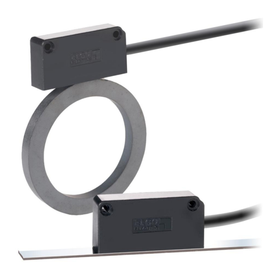
Product Features 5 Product Features Figure 1: RMIX2 with magnet ring Figure 2: RMIX2 with magnetic tape For linear, radial and rotative measurements Direct contactless measurement Excellent price / performance ratio High resolution of 0.025 mm at 4 edge triggering ... -
Page 9: Pulse Diagram
Product Features Pulse Diagram Channels A and B are phase-shifted by 90°. A‘ B‘ The index pulse is output periodically every 4 mm. Z‘ Figure 4: Pulse diagram 6 Technical Data Identification The type label serves for the identification of the unit. It is located on the housing of the sensor and gives the exact type designation (=order reference, see type designation) with the corresponding part number. -
Page 10: Technical Data Sensor
Product Features Technical Data Sensor RMIX2 (Standard version) Mechanical Data Measuring principle incremental Measuring methods linear, radial, rotative Repeat accuracy ± 0.1 mm System accuracy in µm at 20° C ± (25 + 20 x L) L = measuring length in meters Distance sensor - magnetic tape max. -
Page 11: Technical Data Magnetic Tape
Product Features Technical Data Magnetic Tape The magnetic tape (see 10.1 Accessories) consists of two components: The actual magnetic tape which carries the position information A mechanical stainless steel back iron Magnetic tape MB20-20-10-1-R Encoding incremental, single-track system Pole pitch 2 mm −20 °C …... -
Page 12: Technical Data Magnet Rings
Product Features Technical Data Magnet Rings For radial resp. rotative measurements, three types of standard magnet rings ( 10.1 Accessories) are availa- ble: RMIX2 MR Series System accuracy at 20°C < ± 1 % Total error < 0.15 ° (standard) / < 0.007 ° (special applications) Material Hard ferrite 8/22 according to DIN 17410, sintered isotrop Recommended adhesive... -
Page 13: Installation And First Start-Up
Installation and First Start-Up 7 Installation and First Start-Up CAUTION Please read the operating manual carefully before using the device! Strictly observe the Installation instructions! In case of damage caused by failure to observe this operating manual, the warranty expires. ELGO is not liable for any secondary damage and for damage to persons, property or assets. -
Page 14: Installation Of The Magnetic Tape
Installation and First Start-Up Installation of the Magnetic Tape NOTE: External Magnetic Fields The magnetic tape must not be influenced by external magnetic fields! The magnetic tape must not come into direct contact with other magnetic fields (e.g. perma- nent magnets, magnetic clamps, electromagnets, magnetic stands)! This may cause irrepara- ble damage, which will compromise the measuring accuracy or even the functioning. -
Page 15: Figure 7: Handling
Installation and First Start-Up 7.3.2 Handling In order to avoid tension in the tape, it must not be stretched, compressed or twisted. It should be stored with the magnetized plastic tape to the outside. The minimum bending radius is 150 mm. Magnetized plastic tape Steel tape... - Page 16 Installation and First Start-Up The tape must be glued smoothly on the surface. The measuring accuracy decreases if the tape is not even! Before gluing the magnetic tape and the cover tape onto the surface, they should be left lying on the mounting surface for ca.
-
Page 17: Mounting The Sensor
Installation and First Start-Up Mounting the Sensor To mount the sensor head, use 2 x M3 screws of adequate length (see sensor dimensions 6.2). During installation, the specified mounting tolerances must also be observed: 7.4.1 Mounting Tolerances NOTE! The specified tolerances apply equally to mounting with magnetic tape and magnet rings. For detailed information about sensor alignment to magnet rings refer to section ... -
Page 18: Figure 8: Tolerances
Installation and First Start-Up Figure 8: Tolerances 7.4.2 Alignment of RMIX2 with a Magnet Ring Top view: Mounting: RMIX2 center = Ring center 1 mm Lateral offset: ±0.5 ± 0.5 mm Active sensor area Front view: Mounting: Axial offset: RMIX2 center = Ring center ±... -
Page 19: Connections
Connections 8 Connections Signal Cable Pin Assignment Table 3: Pin assignment RMIX2 Open cable ends (standard) Color Function Beschreibung white 0 V (GND) GND (ground) brown 5 VDC / 10 … 30 VDC VCC (power supply input) green Channel A signal output grey Channel B... -
Page 20: Disturbances, Maintenance, Cleaning
Disturbances, Maintenance, Cleaning 9 Disturbances, Maintenance, Cleaning This chapter describes possible causes for disturbances and measures for their removal. In case of increased disturbances, please follow the measures for fault clearance in chapter 9.1. In case of disturbances that cannot be eliminated by following the advice and the fault clear- ance measures given here, please contact the manufacturer (see second page). -
Page 21: Type Designation
Type Designation 10 Type Designation RMIX2 XX.X XXXX Series: RMIX2 = length- and angle measuring system SN-Number: = Standard = First special Version Signal cable length: 01.5 = 1.5m standard cable length (other on request) Resolution: 0025 = 0,025 mm at 4 edge triggering Supply: = 10 …... - Page 22 Notes: - 22 -...
-
Page 23: Index
Index 11 Index Accessories ............. 21 Mounting Tolerances ........17 Accident prevention regulations......5 Operating area ..........13 Alignment of RMIX2 with a Magnet Ring .... 18 Operational safety ..........5 Causes of risk ............ 6 Order reference ..........9 Cleaning ............ - Page 24 Document- No.: 799000559 / Rev. 2 ELGO Electronic GmbH & Co. KG Measuring | Positioning | Control Document- Name: RMIX2-000-MA-E_20-19 Carl - Benz - Str. 1, D-78239 Rielasingen Subject to change - © 2019 Fon:+49 (0) 7731 9339-0, Fax:+49 (0) 7731 28803 ELGO Electronic GmbH &...
Need help?
Do you have a question about the RMIX2 Series and is the answer not in the manual?
Questions and answers