Table of Contents
Advertisement
Advertisement
Table of Contents

Subscribe to Our Youtube Channel
Related Manuals for ELGO Electronic Z16 Series


Summary of Contents for ELGO Electronic Z16 Series
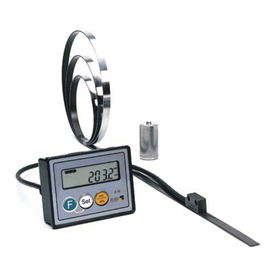
- Page 2 Operation Manual SERIES Z16 Battery powered Length measuring System Predestined for the mobile assembly on manual sledges, carriage and back stop systems 12 months in continuous operation*) Including sensor for magnetic length measuring system Simple operation and assembly LCD-Display with integrated battery status No wiring is necessary Possibility of fraction display in the INCH mode...
-
Page 3: Table Of Contents
Content 1. General Information....................... 3 1.1. Information Operation Manual ..................3 1.2. Explanation of Symbols..................... 3 1.3. Statement of Warranties ....................4 1.4. Demounting and Disposal ....................5 2. Safety ..........................6 2.1. General Cause of Risks..................... 6 2.2. Personal Protective Equipment ..................6 2.3. -
Page 4: General Information
1. General Information 1.1. Information Operation Manual The manual contains important information regarding the handling of the indicator. Precondition for safe operation is the compliance with the specified safety and handling instructions. Moreover, observe the existing local accident prevention regulation and general safety rules. Please read the operation manual carefully before starting to work. -
Page 5: Statement Of Warranties
General Information Hints and commendations ADVERT! ...highlights helpful hints and recommendations for efficient and failure-free operation. Specific safety instructions The following symbols in conjunction with safety instructions are used in order to point out possible hazards: DANGER! ...marks perilous situations by electricity. By non-observance of the safety instructions the possibilities of death or severe injuries exist. -
Page 6: Demounting And Disposal
General Information 1.4. Demounting and Disposal Unless otherwise authorized, dispose the item considering the safety instructions. Before demounting Disconnect the power supply Secure against re-start Disconnect supply lines physically and discharge remaining energy Dispose operating supplies with respect to the environment Disposal Recycle the decomposed elements: Scrap metal elements... -
Page 7: Safety
Safety 2. Safety 2.1. General Cause of Risks This chapter gives an overview about all important safety aspects to guarantee an optimal protection of employees. Non-observance of the instructions mentioned in this operation manual can result in hazardous situations. 2.2. Personal Protective Equipment Employees should wear protective clothing during installation of the device to minimize the risk of accidents. -
Page 8: Conventional Use
Conventional use, Transport, Storage 2.3. Conventional Use The indicator Z16 is for the limited purpose as described in this manual: The indicator Z16 is constructed for measurement uses only. CAUTION! Danger through non-conventional use! Non-intended use and non-observance of this operation manual can lead to dangerous situations. -
Page 9: Check Of Transport
Transport, Storage 3.3. Check of Transport Examine delivery immediately after receiving for completeness and transport damages. In case of externally recognizable transport damages: Do not accept the delivery or do accept under reserve Note extent of damages on the transportation documents or on the delivery note File complaint immediately ADVERT! Claim any damages you recognize as soon as possible. -
Page 10: Product Features
Product features 4. Product Features Z16 battery operated length measuring system The length measuring system Z16 consists of a magnetic sensor (ELGO MS20.25), which is connected tightly with the indicator over a suitable moving chain carriage cable (length 0,1 ... 1m). No wires or connections are required for installation. -
Page 11: Technical Data
Technical Data 5. Technical Data 5.1. Dimensions 5.1.1 Dimensions Indicator Battery chamber Sensor 5.1.2 Dimensions Sensor - 10 -... -
Page 12: Accessories
Technical Data 5.1.3 Accessories 5.1.3.1 MW Z16 Mounting handle MW Z-16 2 x borehole The mounting angle will be mounted with two long screws (contained in the shipping) together with the rear- panel of the unit. It is turn able and can put thus the Z16 in any slopes, in order to enable the user the optimal reading. -
Page 13: Fs 20.25 Guide Rail And Fw 20.60 Guide Carriage
Technical Data 5.1.3.2 FS 20.25 guide rail and FW 20.60 guide carriage Rail: l x w x h = (1or2m) x 25 x 6mm Carriage: l x w x h = 80 x 48 x 25mm The guide rail F520.25 is an aluminium profile with integrated chase in which the magnetic tape is pasted. Additionally the matching guide carriage FW20.60 made of rubber which allows to slip. -
Page 14: Technical Data
Technical Data 5.2 Technical Data Display Z16 7 Decades (Digit height 11mm) LCD-Display Status of Battery and Unit Power supply 1 x Battery (1,5 V) Consumption with encoder < 1 mA at 1,5 V Operation temperature +5 ° up to + 50 ° C Drive speed max. -
Page 15: Installation
Installation 6. Installation 6.1. Qualifications of the Staff Improper maintenance ... can lead to serious personal injuries or property damage. Therefore: Maintenance work should be referred to qualified and authorized by the operator and instructed personnel. 6.2 The Sensor The sensor integrates the magneto resistance test bridges from which, addicted to the track, the counts for the signal processing electronic are formed. -
Page 16: Structure And Function
Structure and Function 7. Structure and Function 7.1 Arrangement of the LCD-Display Battery status monitor ABS = Absolute Mode I NCR = I ncremental Mode Actual Value ( Position) mm or I NCH Mode 7.2 Selecting parameters and input 7.2.1 Parameter level activate For 3 seconds / 1 each x then press With this key the parameter level will be activated. -
Page 17: Parameters
Structure and Function 7.2.5 Parameters Parameter Description Default Parameters P01: AB mm / inch Switching A = 0: mm – Mode A = 1: Inch – Mode (Resolution 0,001 Inch ) Counting direction: B = 0: positive B = 1: negative P03: A Decimal point ( 0 ... -
Page 18: Default Parameter / Calibration
Structure and Function 7.3 Default Parameter / Calibration 7.3.1 Calibration (The Sensor must be installed on the Magnetic tape!) Switch off the unit. press this button While pressing this button switch the unit on again Here, the calibration of the sensor is triggered and "CAL 0" is shown in the display. Now, move the sensor slowly in one direction on the tape. -
Page 19: Functions In Normal Mode
Structure and Function 7.4 Functions in Normal mode 7.4.1 Set datum value 1x press together With this key combination the actual value will be set to the reference value. (Only in the ABS-mode possible, if no offset level is activated.) The reference value is entered in parameter P09. 7.3.2 Switching incremental / absolute incr/abs 1x press... -
Page 20: Accessories
Structure and Function Accessories 7.5.1 Magnetic tape The magnetic tape MB 20-25-10-1-R The magnetic tape consists of 3 components: Sensorseite Sensor side 1,8mm Installation side Befestigungsseite 10mm available lengths 0,5 - 32 m The magnetic, high-flexible rubber tape on the bottom united with: a magnetic flexible steel tape. -
Page 21: Interferences
Interferences 8 Interferences The following chapters describe possible causes for malfunction and the instructions to correct them. If you encounter problems check for proper installation first. Make sure that power is supplied to the system. If you observe recurring errors you might consider electrical interference suppression measures as described in section 7. -
Page 22: Electrical Interference Suppression
Interferences Electrical interference suppression Signal wires should be installed separately from load power lines and with a safe distance of at least 0.5 m to capacitive and inductive interferences such as contactors, relays, motors, switching power supplies, timed controllers. If interferences occur in spite of applying all above mentioned measures proceed as follows: 1. -
Page 23: Emc Information
Interferences EMC information A trouble-free operation of the control devices of the company ELGO Electric GmbH can only be guaranteed if in assembly, wiring and operating the following basic rules are observed and adhered to: • use only shielded signal lines with a minimum diameter of 0.15 mm² •... -
Page 24: Type Designation
Type designation 10 Type Designation Z16 – 000 – 001 – XX.X – X Series (Type) SN-Nummer 000 = Standard 001 = 1st special version Supply 001 = 1,5 V Battery Sensor cable length e.g. 02.0 = 2,0 meter max. Length 2,0 meter Options N = without housing 11 Accessories... -
Page 25: Register
Reference value ..........................19 Security ............................... 6 Storage............................... 8 Suppress interferences ........................22 Symbols .............................. 3 Technical Data ..........................14 Transport ............................8 Type Designation ..........................24 Dok.-Nr. 799000223 Z16-000-E_41-08 Subject to change - © 2008 ELGO Electronic GmbH & Co. KG...
Need help?
Do you have a question about the Z16 Series and is the answer not in the manual?
Questions and answers
Looking for a replacement dimensions sensor for a Z-16 linear scale. We happen to pull the cable out of the old one. If still available could you please forward price as well.