Table of Contents
Advertisement
Quick Links
799000609 / Rev. 7 / 2017-05-12
Translation of the original operating manual
Operating Manual
SERIE LMIX22
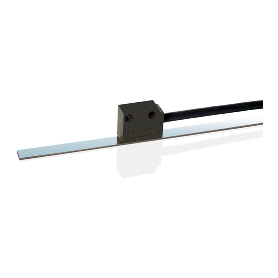
Magnetic incremental Length Measuring System with selectable resolution
With periodic index pulse or optional reference pulse
Distance between sensor / magnetic tape of up to 2.0 mm
Differential HTL or TTL Line Driver outputs
Various resolution at 4 edge triggering available (specified by order)
Repeat accuracy ± 1 increment
Small sensor with integrated evaluation electronic (translator)
Speed proportional output of the square wave signals
Advertisement
Table of Contents

Related Manuals for ELGO Electronic LMIX22-007


Summary of Contents for ELGO Electronic LMIX22-007
-
Page 1: Operating Manual
799000609 / Rev. 7 / 2017-05-12 Translation of the original operating manual Operating Manual SERIE LMIX22 Magnetic incremental Length Measuring System with selectable resolution With periodic index pulse or optional reference pulse Distance between sensor / magnetic tape of up to 2.0 mm ... - Page 2 +49 (0) 7731 9339 – 0 +49 (0) 7731 2 13 11 info@elgo.de Document- No. 799000609 Document- Name LMIX22-000-MA-E_19-17 Document- Revision Rev. 7 Issue Date 2017-05-12 Copyright © 2017, ELGO Electronic GmbH & Co. KG - 2 -...
-
Page 3: Table Of Contents
Operating Area ......................16 Description installation / Mounting of the Magnetic Tape ............. 16 Installation of the Sensor ....................21 Installation of the Magnetic Angle MW-007 for Version LMIX22-007 ........23 Offset ..........................23 Activation of the Device ....................23 Overview: Versions with and without Reference Pulse ...... - Page 4 Contents Extended temperature range (option T) ..........25 Magnetic tape fixation with option T .................. 25 Prefabricated magnetic tape for option T ................25 Connections ....................26 Disturbances, Maintenance, Cleaning ............. 27 11.1 Fault Clearance ......................27 11.2 Re-start after Fault Clearance ................... 27 11.3 Maintenance ........................
-
Page 5: Image Directory
Figure 15: Installation of vertical version (Option L) ................... 21 Figure 16: Tolerances ..........................22 Figure 17: Installation of magnetic angle MW-007 for special version LMIX22-007........23 Figure 18: Overview (standard version) ....................24 Figure 19: Overview (version 007) ......................24 Figure 20: Overview (version 027) ...................... -
Page 6: General, Safety, Transport And Storage
General, Safety, Transport and Storage 4 General, Safety, Transport and Storage 4.1 Information Operating Manual This manual contains important information regarding the handling of the device. For your own safety and operational safety, please ob- serve all safety warnings and instructions. Precondition for safe operation is the compliance with the specified safety and handling instructions. -
Page 7: Demounting And Disposal
General, Safety, Transport and Storage 4.4 Demounting and Disposal Unless acceptance and disposal of returned goods are agreed upon, demount the device considering the safety instructions of this manual and dispose it with respect to the environment. Before demounting, disconnect the power supply and secure against re-start. Then disconnect the supply lines physically and discharge remaining energy. -
Page 8: Conventional Use
General, Safety, Transport and Storage 4.7 Conventional Use The ELGO-device is only conceived for the conventional use described in this manual. The ELGO LMIX22 length measuring system only serves to measure lengths. CAUTION! Danger through non-conventional use! Non-intended use and non-observance of this operating manual can lead to dangerous situations. Therefore: Only use the device as described ... -
Page 9: Product Features
Option L: vertical installation ( 7.3.2.2) 5.1 Version LMIX22-007 Instead of a periodical index pulse (channels Z / Z‘), a single reference pulse (channels R / R‘) occurs at the position where the magnet angle MW-007 (accessorial part 12.5) is installed. For more information refer to sections ... -
Page 10: Functional Principle
Product Features 5.3 Functional Principle The basis of the magnetic incremental encoders consists of a scanning technology, which scans the north and south poles on the coded magnetic tape and produces a single Sine/Cosine wave for each pole. The complete sine/cosine signal process is interpolated electronically. -
Page 11: Technical Data
Technical Data 6 Technical Data 6.1 Identification The type label serves for the identification of the unit. It is located on the housing of the sensor and gives the exact type designation (=order reference, see type designation) with the corresponding part number. Furthermore, the type label contains a unique, traceable device number. -
Page 12: Dimensions Of Guiding Profile And End / Connection Profile
Technical Data 6.3 Dimensions of Guiding Profile and End / Connection Profile Dimensions of FBK80 (guiding profile for magnetic tape BK80) Top view Side view Figure 4: Dimensions FBK80 Dimensions of the End / Connection Profile AFBK80 Screw M2 x 4 Figure 5: Dimensions AFBK 80 - 12 -... -
Page 13: Technical Data Sensor
Technical Data 6.4 Technical Data Sensor LMIX22 (Standard version) Mechanical Data Measuring principle Incremental Repeat accuracy +/- 1 Increment Signal output Speed proportional System accuracy in µm at 20°C +/- (25 µm + 20 µm x L) L = measuring length in meters Distance from sensor to magnetic tape max. -
Page 14: Technical Data Magnetic Tape
Technical Data 6.5 Technical Data Magnetic Tape The magnetic tape consists of two components: The actual magnetic tape which carries the position information A mechanical stainless steel back iron Magnetic Tape MB20-50-10-1-R resp. MB20-50-10-2-R Coding of MB20-50-10-1-R Incremental, single track system (1 x fine interpolation) Coding of MB20-50-10-2-R Incremental, dual track system (1 x fine interpolation, 1 x reference pulse*) *) The position of the reference pulse is determined by order key REF XXXX, see type designation ... -
Page 15: Sensor Position (Active Sensor Area)
Technical Data 6.6 Sensor position (active sensor area) The following figures show the active sensor area (red hatched) for the horizontal and vertical sensor installation. Please read the mounting instructions 7.3.1. 6.6.1 Sensor position with horizontal installation (standard version) Side view Top view Magnetic tape... -
Page 16: Installation And First Start-Up
Installation and First Start-Up 7 Installation and First Start-Up CAUTION Please read the operating manual carefully before using the device! Strictly observe the Instal- lation instructions! In case of damage caused by failure to observe this operating manual, the warranty expires. ELGO is not liable for any secondary damage and for damage to persons, property or assets. -
Page 17: Figure8: Components Of The Magnetic Tape
Installation and First Start-Up 7.2.1 The Magnetic Tape MB20-50-10-1(2)-R In the standard case, the magnetic tape is delivered as described It is installed by gluing it to the respective mounting surface. The magnetic tape consists of 2 pre-assembled components (Figure8: Components of the magnetic tape): A magnetized, flexible plastic tape (Pos. -
Page 18: Figure10: Handling
Installation and First Start-Up 7.2.3 Handling In order to avoid tension in the tape, it must not be stretched, compressed or twisted. It should be stored with the magnetized plastic tape to the outside, the minimum bending radius must be noted here. -
Page 19: Table 1: Chemical Influences
Installation and First Start-Up The tape must be glued smoothly on the surface. The measuring accuracy decreases if the tape is not even! Before gluing the magnetic tape and the cover tape onto the surface, they should be left lying on the mounting surface for ca. -
Page 20: Figure 11: Magnetic Tape Variants
Installation and First Start-Up 7.2.2 Magnetic tape variants Top view Front view Standard (1 track) Magnetic tape: MB20-50-10-1-R Cover tape Magnetic tape N S N S N S N S N S N S N S N S N S N S N S N S N Interference band Version 027 (reference pulse, 2 tracks) Magnetic tape: MB20-50-10-2-R-C-REFXXXX... -
Page 21: Installation Of The Sensor
Installation and First Start-Up 7.3 Installation of the Sensor 7.3.1 Mounting options of the Sensor Standard (horizontal) Option L (vertical) Figure 13: Sensor - mounting options 7.3.2 Installation with Magnetic Tape MB20-50-10-1(2)-R The sensor is not centric positioned in the sensor housing ( 6.6.1, 6.6.2). Therefore it should be ensured that the active (red hatched) sensor area sensor and not the sensor housing is centred on the magnetic tape (... -
Page 22: Figure 16: Tolerances
Installation and First Start-Up 7.3.3 Mounting Tolerances Fasten the sensor head by using two M3 screws. Please note: The tolerances given in the table and in the draw- ings (below) must be observed. Outside these areas the function of the system is not guaranteed! Table 2: Tolerances Tolerances Magnetic tape type... -
Page 23: Installation Of The Magnetic Angle Mw-007 For Version Lmix22-007
Top view Front view Ø 5.5 Figure 17: Installation of magnetic angle MW-007 for special version LMIX22-007 7.5 Offset After the installation of the magnetic tape and the measuring system (sensor head), a value is transmit by the interface. Because this value does not conform to the machine zero point, an offset should to be deposited at the controller side. -
Page 24: Overview: Versions With And Without Reference Pulse
Overview: Versions with and without Reference Pulse 8 Overview: Versions with and without Reference Pulse The following drawings will show the different version types viewed from above. 8.1 Version 000 (standard) Standard, without reference pulse (single track tape) Magnetic tape: MB20-50-10-1-R N S N S N S N S N S N S N S N S N S N S N S N S N Sensor Fine interpolation track... -
Page 25: Extended Temperature Range (Option T)
Extended temperature range (option T) 9 Extended temperature range (option T) When ordering option T ( 12.1) the LMIX22 sensor is supplied with an extended temperature range which is particularly suitable for use in rough environmental conditions (e.g. outdoor solar systems). The extended tem- perature range with option T is -40 …... -
Page 26: Connections
Connections 10 Connections The LMIX22 standard measuring system is delivered with open cable ends. The versions with plug connection are options that need to be specified in the order ( 12.1). Table 3: Pin assignment with open cable ends Connection type Colour Function Description... -
Page 27: Disturbances, Maintenance, Cleaning
Disturbances, Maintenance, Cleaning 11 Disturbances, Maintenance, Cleaning This chapter describes possible causes for disturbances and measures for their removal. In case of increased disturbances, please follow the measures for fault clearance in chapter 11.1. In case of disturbances that cannot be eliminated by following the advice and the fault clearance measures given here, please contact the manufacturer (see second page). -
Page 28: Maintenance
Disturbances, Maintenance, Cleaning 11.3 Maintenance The device is maintenance-free. WARNING! Danger through non-conventional maintenance! Non-conventional maintenance can lead to severe injuries and damage of property. Therefore: Maintenance works may only be completed by staff that has been authorized and trained by the operator. 11.4 Cleaning WARNING! The device can only be cleaned with a damp cloth, do not use aggressive cleanser! -
Page 29: Type Designation
Type Designation 12 Type Designation 12.1 Type Designation Sensor LMIX22 BB.B CCCC Serie/Type: LMIX22 Linear Encoder Version- No.: 000 = Standard 007 = Reference pulse on magnetic angle 027 = Reference pulse on magnetic tape track Signal cable length: 01.5 = 1.5 m (Standard length) Resolution in µm: Indicate key values, see table „LMIX22 Resolutions“... -
Page 30: Type Designation Magnetic Tape
Type Designation 12.3 Type Designation Magnetic Tape MB20 FFFFFFF Designation: MB20 = Incremental magnetic tape Basic pole pitch: Basic pole pitch with a resolution of 100 µm: 50 = 5 mm pole pitch (e. g. LMIX22) Tape width: Tape width in mm: 10= 10 mm Number of tracks: Number of tracks... -
Page 31: Accessories
Single track magnetic tape for LMIX22-000 and LMIX22-007 MB20-50-10-2-R Dual track magnetic tape for LMIX22-027 (with reference pulse track) MW-007 1 magnetic angle with reference pulse for special version LMIX22-007 733282100 End cap 10 mm 1 end cap (10 mm) for magnetic tape... - Page 32 Type Designation Notes: - 32 -...
- Page 33 Type Designation Notes: - 33 -...
- Page 34 Type Designation Notes: - 34 -...
-
Page 35: Index
Index 13 Index Accessories ............. 31 Operational safety ..........6 Accident prevention regulations......6 Order reference ..........11 Causes of risk ............ 7 Packaging material ..........8 Cleaning ........... 27, 28 Product features ..........9 Connections ............ 26 Protection against contact ........ 16 Conventional use .......... - Page 36 Index Document- No.: 799000609 / Rev. 7 ELGO Electronic GmbH & Co. KG Measuring | Positioning | Control Document- Name: LMIX22-000-MA-E_19-17 Carl - Benz - Str. 1, D-78239 Rielasingen Subject to change - © 2017 Fon:+49 (0) 7731 9339-0, Fax:+49 (0) 7731 28803 Internet: www.elgo.de, Mail: info@elgo.de...
Need help?
Do you have a question about the LMIX22-007 and is the answer not in the manual?
Questions and answers