Table of Contents
Advertisement
Quick Links
799000722 / Rev. 4 / 2019-01-22
Translation of the original operating manual
Operating Manual
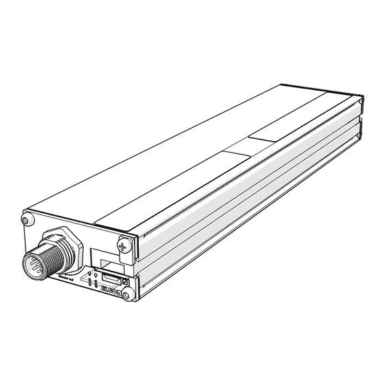
SERIE LIMAX02 M
Magnetic Absolute Shaft Information System
Position measuring for lifting heights up to 130 meters
Travel speed up to 4 m/s
Insensitive to dirt, smoke and humidity
Resolution up to 0.0625 mm
Easy and flexible mounting
No referencing necessary
Magnetic tape may be installed vertically freely suspended or horizontally
Wear-free, contactless and noiseless measuring principle
Advertisement
Table of Contents

Related Manuals for ELGO Electronic LIMAX02 M Serie


Summary of Contents for ELGO Electronic LIMAX02 M Serie
- Page 1 799000722 / Rev. 4 / 2019-01-22 Translation of the original operating manual Operating Manual SERIE LIMAX02 M Magnetic Absolute Shaft Information System Position measuring for lifting heights up to 130 meters Travel speed up to 4 m/s Insensitive to dirt, smoke and humidity ...
-
Page 2: D-78239 Rielasingen-Worblingen
+49 (0) 7731 9339 – 0 +49 (0) 7731 2 13 11 info@elgo.de Document- No. 799000722 Document - Name LIMAX02-M-00-MA-E_04-19 Document- Revision Rev. 4 Issue Date 2019-01-22 Copyright © 2019, ELGO Electronic GmbH & Co. KG - 2 -... -
Page 3: Table Of Contents
Contents 1 Contents Contents ..................... 3 General, Safety, Transport and Storage ............ 4 Information Operating Manual ..................4 Explanation of Symbols ....................4 Statement of Warranties ....................5 Demounting and Disposal ....................5 General Causes of Risk ....................5 Personal Protective Equipment ..................5 Conventional Use ...................... -
Page 4: General, Safety, Transport And Storage
General, Safety, Transport and Storage General, Safety, Transport and Storage Information Operating Manual This manual contains important information regarding the handling of the device. For your own safety and operational safety, please ob- serve all safety warnings and instructions. Precondition for safe operation is the compliance with the specified safety and handling instructions. Moreover, the existing local accident prevention regulations and the general safety rules at the site of operation have to be observed. -
Page 5: Statement Of Warranties
General, Safety, Transport and Storage Statement of Warranties The producer guarantees the functional capability of the process engineering and the selected parameters. Demounting and Disposal Unless acceptance and disposal of returned goods are agreed upon, demount the device considering the safety instructions of this manual and dispose it with respect to the environment. -
Page 6: Conventional Use
General, Safety, Transport and Storage Conventional Use The product described in this manual was developed to execute safety-related functions as a part of an entire assembly or machine. It is the responsibility of the manufacturer of a machine or installation to ensure the proper functioning of the system. The ELGO-device is only conceived for the conventional use described in this manual. -
Page 7: Product Features
Product Features 3 Product Features The absolute shaft information system LIMAX02 M with its significant advantages is a particularly affordable, non-sensitive and easy-to-install alternative to conventional shaft information systems. Due to the absolute measurement principle, referencing is not required after commissioning. Compared to other shaft information systems, LIMAX02 M is characterized by an extraordinarily low price. -
Page 8: Technical Data
Technical Data 4 Technical Data Identification The type label serves for the identification of the unit. It is located on the housing of the sensor and gives the exact type designation (=order reference, see type designation) with the corresponding part number. Further- more, the type label contains a unique, traceable device number. -
Page 9: Dimensions Magnetic Tape
Technical Data Dimensions Magnetic Tape Scale 5:1 Fig.2: Dimensions Magnetic Tape Technical Data Sensor LIMAX02 M (Standard version) Mechanical Data Measuring principle absolute Repeat accuracy +/- 1 mm System accuracy in µm at 20°C +/- (1000 + 50 x L[m]) L = measuring length in meter Basic pole pitch 8 mm... -
Page 10: Technical Data Magnetic Tape
Technical Data Technical Data Magnetic Tape The magnetic tape consists of two components: The actual magnetic tape which carries the position information A mechanical stainless steel back iron TEMPLATE Magnetic Tape AB20-80-10-1-R-D-15-BK80 Coding absolute, one track system Pole pitch 8 mm -20 °C …... -
Page 11: Installation And First Start-Up
Installation and First Start-Up 5 Installation and First Start-Up CAUTION Please read the operating manual carefully before using the device! Strictly observe the Instal- lation instructions! In case of damage caused by failure to observe this operating manual, the warranty expires. ELGO is not liable for any secondary damage and for damage to persons, property or assets. -
Page 12: Description Mounting / Installation Of The Sensor
Installation and First Start-Up Description Mounting / Installation of the Sensor 5.2.1 Installation Principle Upper tape fixation Upper tape fixation Sensor Sensor Magnetic tape Magnetic tape Guide rail Guide rail Sway guard Spring Tension weight Fig. 3: Installation with tension weight Fig. -
Page 13: Description Installation / Mounting Of The Magnetic Tape
Installation and First Start-Up 5.2.1 Installation of the Sensor The sensor is fixated on the cabin or on the car frame. The mounting position is basically determined by the condition. The integrated mounting notch on the housing of the sensor head allow for a very simple and self- explanatory installation from one side. - Page 14 Installation and First Start-Up 5.3.2 Installation Concept 5.3.2.1 Basic principle for the mounting NOTE! The magnetic tape itself is not designed to withstand excessive mechanical wear. It is there- fore important to ensure that the system is installed such that the mechanical contact between tape and sensor head is mainly between the steel tape and the polymer sensor guide.
- Page 15 Installation and First Start-Up 5.3.3 Installation Procedure Attach the top end of the tape in the shaft head. Ideally use an ELGO Mounting Kit. Check for correct orientation of the tape. The arrows on the magnetic side must point in upward direction. Shaft head Shaft pit Fig.
- Page 16 Installation and First Start-Up Tape is Tape is Tape is flat skewed in skewed in in the guide the guide the guide Fig. 9: Assessment of the guiding rail of the tape in the sensor - twisted magnetic tape Tape is Tape is Tape is centered in...
- Page 17 Installation and First Start-Up IMPORTANT: Installation check! Values for tape tension and offset between tape and sensor are guidelines based on experience. But in any case, a proper check after installation is mandatory. It must absolutely be avoided that the magnetic side constantly grinds on the sensor body during operation.
- Page 18 Installation and First Start-Up If the installation check reveals that the tape slides on magnetic side, start to increase the offset between sensor and tape. Values of up to 5 cm are acceptable. If this measure does not solve the problem it is very likely that the tape is not plumb in the shaft.
-
Page 19: Connections And Interfaces
Connections and Interfaces 6 Connections and Interfaces LEDs (Operating Status and Notices) The LED’s located on the front serve for monitoring of operating conditions. Fig. 12: LED signals on the upper side of the sensor GREEN For CANopen device RUN-LED according to DR 303-3 Other devices Interface state, flashes during active communication For CANopen device... -
Page 20: Can Interface
Connections and Interfaces CAN Interface 6.2.1 CANopen DS406 and DS417 For LIMAX02 M the CANopen Interfaces DS406 (Encoder profile) und DS417 (Lift profile) are available. These interfaces are configured by default as follows: Table 1: Configuration of CANopen DS406 CANopen DS406 Bit rate: 250 kbit/s Identifier:... - Page 21 Connections and Interfaces 6.2.3 Command Descriptions 6.2.3.1 Initial Operation After starting the CANopen device is in the Pre-operational Mode ( 6.2.5.2) and therefore doesn’t send any position data. In order to achieve this, the device needs to be set into Operational Mode ( 6.2.5.1) and if necessary the sending cycle of the position data has to be adjusted (...
- Page 22 Connections and Interfaces CANopen Master device Set cycle time for position data DLC: 2B UU VV XXX = 600h + node-ID Example.: 604h for the device with node-ID 4 UU = 00h (DS406), 06h(DS417) VV = 18h (DS406), 19h(DS417) YY = LSB of cycle time in milliseconds ZZ = MSB of cycle time in milliseconds Example: for a cycle time of 10ms (Ah) is YY = 0Ah and ZZ = 00h...
- Page 23 Connections and Interfaces 6.2.5 Changing the Operating Modes 6.2.5.1 Changing the device into the Operational Mode In the Operational Mode the communication of the device is fully functional. The following CAN-message causes the change of all CANopen participants into the Operational Mode. CANopen Master device...
- Page 24 Connections and Interfaces The following CAN-message causes the change into the LSS Configuration Mode. CANopen Master device Changing all participants into LSS Configuration Mode DLC: Fig. 21: Changing into the LSS Configuration Mode 6.2.6.2 Saving the parameters in the LSS Mode In order not to lose the changes in case of a power failure, they have to be saved in the non-volatile memory of the CANopen device.
- Page 25 Connections and Interfaces 6.2.7 Setting the Baud rate 1. Change the device into the Stopped mode (see section 6.2.5.3) 2. Change the device into the LSS Configuration Mode (see section 6.2.6.1) 3. Change baud rate according to the following command: CANopen Master device...
-
Page 26: Ssi Interface
Connections and Interfaces SSI Interface 6.3.1 Function Principle If the clock is not interrupted for the time Tm-T/2 (output of further 25 periods), the shift register clocks once again the same data value (error recognition in the evaluation). Some encoders contain a Power Failure Bit (PFB). -
Page 27: Rs422 And Rs485* Interface
Connections and Interfaces RS422 and RS485* Interface *) Attention: RS485 only unidirectional If the measuring system is equipped with an RS422 or RS485 interface, the data communication has the follow- ing format: 9600 bit/s baud (other bitrates on request) 1 Start bit 8 data bits 1 stop bit no parity... - Page 28 Connections and Interfaces 6.4.2.2 Position request of LIMAX02 M with the address “i” To LIMAX02 M answer Byte Adr. check = characterises the message as position request ABS-Position = address of the LIMAX02 M (0Bh – 7Fh) to request Bit 0 has the value 10 µm, position values are always smaller than FFFF00h 6.4.2.3 A LIMAX02 M address request Attach in each case only one LIMAX02 M e.g.
- Page 29 Connections and Interfaces Table 5: Error-codes of an addressable LIMAX02 M Code Meaning Wrong sequence of bytes sent to LIMAX02 M, for example if 4. Byte after STX is no ETX or the Byte after STX is not 0x04, 0x05 or 0x06. Receiving Error / Interface Error (for example if a message with a wrong baud rate was sent etc.) Invalid LIMAX02 M address: appears after trying to assign an address smaller 0Bh or bigger 7Fh to LIMAX02 M.
- Page 30 Connections and Interfaces 6.4.3 Pin Assignment RS422 Table 6: Pin Assignment RS422 8-pin M12 (male) connector Colour Function White 0V / GND Brown +24 VDC Green RS422_RX+ Yellow RS422_RX- Grey RS422_TX+ Pink RS422_TX- Blue N.C. N.C. Housing Blank Cable shield 6.4.4 Pin Assignment RS485 Table 7: Pin Assignment RS485...
-
Page 31: Disturbances, Maintenance, Cleaning
Disturbances, Maintenance, Cleaning 7 Disturbances, Maintenance, Cleaning This chapter describes possible causes for disturbances and measures for their removal. In case of increased disturbances, please follow the measures for fault clearance in chapter 7.1. In case of disturbances that cannot be eliminated by following the advice and the fault clearance measures given here, please contact the manufacturer (see second page). -
Page 32: Maintenance
Disturbances, Maintenance, Cleaning Maintenance The device is maintenance-free. WARNING! Danger through non-conventional maintenance! Non-conventional maintenance can lead to severe injuries and damage of property. Therefore: Maintenance works may only be completed by staff that has been authorized and trained by the operator. Cleaning WARNING! The device can only be cleaned with a damp cloth, do not use aggressive cleanser! -
Page 33: Type Designation
Type Designation 8 Type Designation Type Designation LIMAX2M 1000 CO0T M12M Series/Type: LIMAX2M = LIMAX2 MINI (1-channel) SN-number: = standard version = 1. special version (etc.) Signal cable length: = M12 connector on device (standard) = 3.0 m, fixed cable outlet on device = 5.0 m, fixed cable outlet on device Resolution: 62N5... -
Page 34: Accessories
Type Designation Accessories Order Designation Description AB20-80-10-1-R-D-15-BK80 Magnetic tape for series LIMAX02 M Installation kit LIMAX RMS For centrally guided lift cars Installation kit LIMAX RMS 90 Angled for cabins with rucksack layout Installation kit LIMAX S-RMS With safety position switch ... - Page 35 Type Designation Fig. 30: Cable M12F5 - D9M Table 9: Connections Cable M12F5 - open cable ends M12F5 Function Brown N.C. White +24 VDC Blue 0 V / GND Black CAN H Grey CAN L Chassis Chassis Cable shield Cable shield Order Designation Description CABLE-LIMAX2M-M12F5-XX.X...
- Page 36 Type Designation Table 10: Connections Cable M12F - open cable ends M12F8 Color SSI Function RS422 Function White 0 V / GND 0 V / GND Brown +24 VDC +24 VDC Green SSI_CLK+ RS422_RX+ Yellow SSI_CLK− RS422_RX− Grey SSI_DATA+ RS422_TX+ Pink SSI_DATA−...
- Page 37 Type Designation 8.2.3 Mounting Angle Fig. 33: Mounting angle Order Designation Description LIMAX02-M MW Mounting angle for LIMAX02-M - 37 -...
- Page 38 Type Designation Notes: - 38 -...
-
Page 39: Index
Index 9 Index Accident prevention regulations......4 Magnetic Tape Structure ........10 CAN Interface and Protocols ......20 Maintenance ..........31, 32 Causes of risk ............ 5 Operating area ..........11 Changing the Operating Modes ....... 23 Operational safety ..........4 Cleaning ........... -
Page 40: Carl-Benz-Str
Document- No.: 799000722 / Rev. 4 ELGO Electronic GmbH & Co. KG Measuring | Positioning | Control Document- Name : LIMAX02-M-00-MA-E_04-19 Carl - Benz - Str. 1, D-78239 Rielasingen Subject to change - © 2019 Fon:+49 (0) 7731 9339-0, Fax:+49 (0) 7731 28803 Internet: www.elgo.de, Mail: info@elgo.de...
Need help?
Do you have a question about the LIMAX02 M Serie and is the answer not in the manual?
Questions and answers