
Related Manuals for AXIOMTEK PICO512


Summary of Contents for AXIOMTEK PICO512
- Page 1 PICO512 ® Generation Intel Core i7/ i5/ i3 ® and Celeron Processors Pico-ITX Board User’s Manual...
-
Page 2: Disclaimers
Axiomtek does not make any commitment to update the information in this manual. Axiomtek reserves the right to change or revise this document and/or product at any time without notice. No part of this document may be reproduced, stored in a retrieval system, or transmitted, in any form or by any means, electronic, mechanical, photocopying, recording, or otherwise, without the prior written permission of Axiomtek Co., Ltd. -
Page 3: Esd Precautions
It discharges static electricity from your body. Wear a wrist-grounding strap, available from most electronic component stores, when handling boards and components. Trademarks Acknowledgments Axiomtek is a trademark of Axiomtek Co., Ltd. ® ® Intel and Celeron are trademarks of Intel Corporation. -
Page 4: Table Of Contents
Table of Contents Disclaimers ..................... ii ESD Precautions ................... iii Chapter 1 Introduction ..........1 Features ....................2 Specifications ..................2 Utilities ....................3 Chapter 2 Board and Pin Assignments ....5 Board Dimensions and Fixing Holes ..........5 Board Layout ..................7 Assembly Drawing ................ - Page 5 System Memory ................. 23 I/O Port Address Map ................ 24 Interrupt Controller (IRQ) Map ............25 Memory Map ..................31 Chapter 4 AMI BIOS Setup Utility ......33 Starting ....................33 Navigation Keys ................33 Main Menu ..................35 Advanced Menu ................. 36 Chipset Menu ..................
- Page 6 This page is intentionally left blank.
-
Page 7: Chapter 1 Introduction
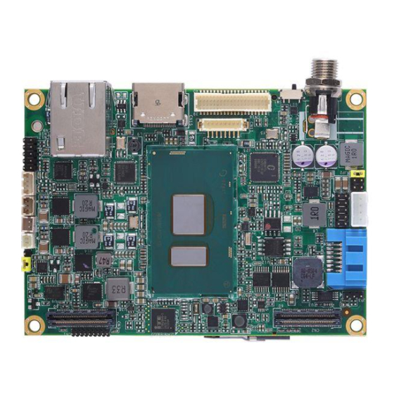
PICO512 Pico-ITX Board Chapter 1 Introduction ® ® The PICO512 is a Pico-ITX board with 7 Generation Intel Core i7/ i5/ i3 and Celeron processor that delivers outstanding system performance through high-bandwidth interfaces, multiple I/O functions for interactive applications and various embedded computing solutions. -
Page 8: Features
PICO512 Pico-ITX Board Features ® ® Generation Intel Core i7/ i5/ i3 and Celeron ULT processor 1 DDR4 SO-DIMM supports up to 16GB memory capacity 1 USB 2.0 port and 1 Gigabit Ethernet port 1 8-bit digital I/O interface ... -
Page 9: Utilities
PICO512 Pico-ITX Board Expansion Interface One full-size PCI-Express Mini Card (with mSATA supported) complies with PCI-Express Mini Card Spec. V1.2. Low/high speed board to board connectors. Power Input DC jack power connector, co-layout with 1x2-pin right angle connector. - Page 10 PICO512 Pico-ITX Board This page is intentionally left blank. Introduction...
-
Page 11: Board And Pin Assignments
PICO512 Pico-ITX Board Chapter 2 Board and Pin Assignments Board Dimensions and Fixing Holes Top View Board and Pin Assignments... - Page 12 PICO512 Pico-ITX Board Bottom View Side View Board and Pin Assignments...
-
Page 13: Board Layout
PICO512 Pico-ITX Board Board Layout Top View Side View Board and Pin Assignments... - Page 14 PICO512 Pico-ITX Board Bottom View Board and Pin Assignments...
-
Page 15: Assembly Drawing
PICO512 Pico-ITX Board Assembly Drawing For thermal dissipation, a thermal solution enables the PICO512’s components to dissipate heat efficiently. All heat generating components are thermally conducted to the heatsink in order to avoid hot spots. Images below illustrate how to install the thermal solution on PICO512. - Page 16 PICO512 Pico-ITX Board Use the following four screws to secure heatsink on heatspreader. The PICO512 has four assembly holes for installing thermal solution. Align and firmly secure the plate to the PICO512. Be careful not to over-tighten the screws. Board and Pin Assignments...
-
Page 17: Jumper And Switch Settings
And remove jumper clip from 2 jumper pins to open. Below illustration shows how to set up jumper. Properly configure jumper and switch settings on the PICO512 to meet your application purpose. Below you can find a summary table of jumpers, switch and onboard default settings. -
Page 18: Restore Bios Optimal Defaults (Jp1)
PICO512 Pico-ITX Board 2.4.1 Restore BIOS Optimal Defaults (JP1) Put jumper clip to pin 2-3 for a few seconds then move it back to pin 1-2. Doing this procedure can restore BIOS optimal defaults. Function Setting Normal (Default) 1-2 close... -
Page 19: Connectors
PICO512 Pico-ITX Board Connectors Signals go to other parts of the system through connectors. Loose or improper connection might cause problems, please make sure all connectors are properly and firmly connected. Here is a summary table which shows all connectors on the hardware. -
Page 20: Board To Board Connectors (Cn2 And Cn3)
PICO512 Pico-ITX Board 2.5.1 Board to Board Connectors (CN2 and CN3) CN2 is a 2x30-pin board to board connector. It is compatible with Samtec SMD LSHM-130-04.0-F-DV-A-N-K-TR-2x30P. The pin assignments are given as follows. Signal Signal HD_LINK_SYNC HD_LINK_BCLK HD_LINK_SDI HD_LINK_RST HD_LINK_SDO 3.3V AUDIO Power... - Page 21 +V5S +V3.3_SBY +V5S It is suggested to insert I/O board (AX93A00, AX93A01, AX93A02 or AX93A09) into CN2 and CN3 on PICO512. Note1 If sets IO board (AX93A00.AX93A01) Display (VGA or HDMI) as Primary, Note2 then secondary (LVDS) will be disabled due to intel graphic limitation.
-
Page 22: Sata Connector (Cn4)
PICO512 Pico-ITX Board 2.5.2 SATA Connector (CN4) This Serial Advanced Technology Attachment (Serial ATA or SATA) connector is for high-speed SATA interface port. It is a computer bus interface for connecting to devices such as hard disk drive. Signal 2.5.3 CMOS Battery Connector (CN5) This connector is for CMOS battery interface. -
Page 23: Sata Power Connector (Cn8)
PICO512 Pico-ITX Board 2.5.6 SATA Power Connector (CN8) The CN8 is a 4-pin (pitch=2.0mm) wafer connector, which is compliant with JST B4B-PH-K-S, for SATA power interface. Signal +12V 2.5.7 Front Panel Connector (CN9) This is a 5x2-pin (pitch=2.0mm) pin header for power and reset button interface. -
Page 24: Usb 2.0 Wafer Connector (Cn10)
PICO512 Pico-ITX Board 2.5.8 USB 2.0 Wafer Connector (CN10) This is a 4-pin (pitch=1.25mm) wafer connector, which is compliant with Molex 530470410, for USB 2.0 interface. Signal USB3_PWR67 2.5.9 Inverter Connector (CN11) This is DF13-8S-1.25C 8-pin connector for inverter. We strongly recommend you to use the matching DF13-8S-1.25C connector to avoid malfunction. -
Page 25: Dc Jack Power Connector W/ Screw (Cn14)
PICO512 Pico-ITX Board 2.5.12 DC Jack Power Connector w/ Screw (CN14) The CN14 is a DC jack with screw. Firmly insert at least 60W adapter into this connector. Loose connection may cause system instability make sure components/devices properly installed before connecting. -
Page 26: Lvds Connector (Cn16)
PICO512 Pico-ITX Board 2.5.14 LVDS Connector (CN16) This board has a 2x20-pin connector for LVDS LCD interface. It is strongly recommended to use the matching JST SHDR-40VS-B connector for LVDS interface. Pin 1~6 VCCM can be set to +3.3V, +5V or +12V by setting JP2 (see section 2.4.2). - Page 27 PICO512 Pico-ITX Board 24-bit single channel 18-bit dual channel Pin Signal Pin Signal Pin Signal Pin Signal VCCM VCCM VCCM VCCM VCCM VCCM VCCM VCCM VCCM VCCM VCCM VCCM 10 GND 10 GND 11 N.C 12 N.C 11 N.C 12 Channel B D0- 13 N.C...
-
Page 28: I2C Connector (Cn17)
PICO512 Pico-ITX Board 2.5.15 I2C Connector (CN17) This is a 3-pin (pitch=1.25mm) wafer connector. The I2C is a simple bus for the purpose of lightweight communication. Signal I2C_CLK_SBY I2C_DAT_SBY 2.5.16 Full-size PCI-Express Mini Card and mSATA Connector (SCN1) This is a full-size PCI-Express Mini Card connector on the bottom side complying with PCI-Express Mini Card Spec. -
Page 29: Chapter 3 Hardware Description
Make sure all correct settings are arranged for your installed microprocessor to prevent the CPU from damages. BIOS The PICO512 uses AMI Plug and Play BIOS with a single 128Mbit SPI Flash. System Memory The PICO512 supports one 260-pin DDR4 SO-DIMM socket for maximum memory capacity up to 16GB DDR4 SDRAMs. -
Page 30: I/O Port Address Map
PICO512 Pico-ITX Board I/O Port Address Map Hardware Description... -
Page 31: Interrupt Controller (Irq) Map
PICO512 Pico-ITX Board Interrupt Controller (IRQ) Map The interrupt controller (IRQ) mapping list is shown as follows: Hardware Description... - Page 32 PICO512 Pico-ITX Board Hardware Description...
- Page 33 PICO512 Pico-ITX Board Hardware Description...
- Page 34 PICO512 Pico-ITX Board Hardware Description...
- Page 35 PICO512 Pico-ITX Board Hardware Description...
- Page 36 PICO512 Pico-ITX Board Hardware Description...
-
Page 37: Memory Map
PICO512 Pico-ITX Board Memory Map The memory mapping list is shown as follows: Hardware Description... - Page 38 PICO512 Pico-ITX Board This page is intentionally left blank. Hardware Description...
-
Page 39: Ami Bios Setup Utility
PICO512 Pico-ITX Board Chapter 4 AMI BIOS Setup Utility The AMI UEFI BIOS provides users with a built-in setup program to modify basic system configuration. All configured parameters are stored in a flash chip to save the setup information whenever the power is turned off. This chapter provides users with detailed description about how to set up basic system configuration through the AMI BIOS setup utility. - Page 40 PICO512 Pico-ITX Board Hot Keys Description Left/Right The Left and Right <Arrow> keys allow you to select a setup screen. The Up and Down <Arrow> keys allow you to select a setup screen or Up/Down sub-screen. The Plus and Minus <Arrow> keys allow you to change the field value of a +...
-
Page 41: Main Menu
PICO512 Pico-ITX Board Main Menu When you first enter the setup utility, you will enter the Main setup screen. You can always return to the Main setup screen by selecting the Main tab. System Time/Date can be set up as described below. -
Page 42: Advanced Menu
PICO512 Pico-ITX Board Advanced Menu The Advanced menu also allows users to set configuration of the CPU and other system devices. You can select any of the items in the left frame of the screen to go to the sub menus: ►... - Page 43 PICO512 Pico-ITX Board Hardware Monitor This screen monitors hardware health status. This screen displays the temperature of system and CPU, and system voltages (VBAT and +3.3V/+3.3V_SBY/+5V). Utility Configuration BIOS Flash Utility BIOS flash utility configuration. For more detailed information, please refer to Appendix D.
- Page 44 PICO512 Pico-ITX Board ACPI Settings You can check this screen for the ACPI configuration. ACPI Sleep State When the suspend button is pressed, the ACPI sleep state is S3 (Suspend to RAM). AMI BIOS Setup Utility...
- Page 45 PICO512 Pico-ITX Board CPU Configuration This screen shows the CPU Configuration. Intel (VMX) Virtualization Technology Enable or disable Intel Virtualization Technology. When enabled, a VMM (Virtual Machine Mode) can utilize the additional hardware capabilities. It allows a platform to run multiple operating systems and applications independently, hence enabling a single computer system to work as several virtual systems.
- Page 46 PICO512 Pico-ITX Board SATA Configuration In the SATA Configuration menu, you can see the current installed hardware in the SATA ports. During system boot up, the BIOS automatically detects the presence of SATA devices. SATA Mode Selection AHCI (Advanced Host Controller Interface) mode is how SATA controller(s) operate.
- Page 47 PICO512 Pico-ITX Board PCH-FW Configuration This screen displays ME Firmware information. AMT Configuration Use this screen to configure AMT parameters. Intel AMT ® Enable or disable Intel Active Management Technology BIOS Extension. The default is Enabled. For more detailed information, please refer to Appendix C.
- Page 48 PICO512 Pico-ITX Board USB Configuration USB Devices Display all detected USB devices which are installed in connector CN10 on PICO512, CN6 and CN7 on AX93A00, CN4 and CN6 on AX93A01, USB1~USB4 on AX93A02 or CN3 on AX93A09. AMI BIOS Setup Utility...
- Page 49 This option appears only if an I/O board is installed. BIOS will auto-detect all supported functions and you can use it to change settings on the I/O board. The PICO512 supports the following I/O boards: AX93A00, AX93A01, AX93A02 and AX93A09.
- Page 50 PICO512 Pico-ITX Board Onboard Device Configuration You can use this screen to select options for the 8-bit Digital I/O Configuration. A description of the selected item appears on the right side of the screen. For items marked with “”, please press <Enter> for more options.
- Page 51 PICO512 Pico-ITX Board Module Configuration This screen is available only if an I/O board with serial ports is connected. Serial Port Disabled: If I/O board is not installed. Enabled: If I/O board is installed, this option will be enabled automatically. The optimal setting for base I/O address is 3F8h and for interrupt request address is IRQ4, see image below.
- Page 52 PICO512 Pico-ITX Board Serial Port 2 Configuration Serial Port Disabled: If I/O board is not installed. Enabled: If I/O board is installed, this option will be enabled automatically. The optimal setting for base I/O address is 3E8h and for interrupt request address is IRQ3, see image below.
-
Page 53: Chipset Menu
PICO512 Pico-ITX Board Chipset Menu The Chipset menu allows users to change the advanced chipset settings. You can select any of the items in the left frame of the screen to go to the sub menus: ► PCH-IO Configuration ►... - Page 54 PICO512 Pico-ITX Board PCH-IO Configuration HD Audio Control detection of the HD Audio device. Configuration options are Disabled and Enabled. AMI BIOS Setup Utility...
- Page 55 PICO512 Pico-ITX Board System Agent (SA) Configuration This screen shows System Agent version information and provides function for specifying related parameters. Graphics Configuration Use this item to configure internal graphics controller. Memory Configuration Use this item to refer to the information related to system memory.
- Page 56 PICO512 Pico-ITX Board Graphics Configuration LVDS Panel Type Select LVDS panel resolution; see the selection options in image above. AMI BIOS Setup Utility...
- Page 57 HDMI(ONBOARD). The image above shows option list in Primary IGFX Boot Display when no I/O board is installed. When powering on PICO512 for the first time, video device must be plugged into HDMI port (CN15). Then, after first power on, you can set VGA on AX93A00 or HDMI on AX93A01 as primary IGFX boot display.
- Page 58 PICO512 Pico-ITX Board When AX93A00 is installed, the Secondary IGFX Boot Display option appears and the Primary IGFX Boot Display option list will be LVDS, HDMI(ONBOARD) and VGA, see image below. Otherwise when AX93A01 is installed, the Secondary IGFX Boot Display option appears and the Primary IGFX Boot Display option list will be LVDS, HDMI(ONBOARD) and HDMI, see image below.
- Page 59 PICO512 Pico-ITX Board Secondary IGFX Boot Display Select secondary display device. The default is Disabled. When AX93A00 is installed, the option list in Secondary IGFX Boot Display will be Disabled and VGA, see image below. Otherwise when AX93A01 is installed, the option list in Secondary IGFX Boot Display will be Disabled and HDMI.
-
Page 60: Security Menu
PICO512 Pico-ITX Board Security Menu The Security menu allows users to change the security settings for the system. Administrator Password This item indicates whether an administrator password has been set (installed or uninstalled). User Password This item indicates whether an user password has been set (installed or uninstalled). -
Page 61: Boot Menu
PICO512 Pico-ITX Board Boot Menu The Boot menu allows users to change boot options of the system. Bootup NumLock State Use this item to select the power-on state for the keyboard NumLock. Quiet Boot Select to display either POST output messages or a splash screen during boot-up. -
Page 62: Save & Exit Menu
PICO512 Pico-ITX Board Save & Exit Menu The Save & Exit menu allows users to load your system configuration with optimal or fail-safe default values. Save Changes and Exit When you have completed the system configuration changes, select this option to leave Setup and return to Main Menu. - Page 63 PICO512 Pico-ITX Board Discard Changes Select this option to quit Setup without making any permanent changes to the system configuration. Select Discard Changes from the Save & Exit menu and press <Enter>. Select Yes to discard changes. Restore Defaults It automatically sets all Setup options to a complete set of default settings when you select this option.
- Page 64 PICO512 Pico-ITX Board This page is intentionally left blank. AMI BIOS Setup Utility...
-
Page 65: Appendix A Watchdog Timer
PICO512 Pico-ITX Board Appendix A Watchdog Timer A.1 About Watchdog Timer After the system stops working for a while, it can be auto-reset by the watchdog timer. The integrated watchdog timer can be set up in the system reset mode by program. - Page 66 PICO512 Pico-ITX Board This page is intentionally left blank. Watchdog Timer...
-
Page 67: Appendix B Digital I/O
PICO512 Pico-ITX Board Appendix B Digital I/O B.1 About Digital I/O The onboard GPIO or digital I/O has 8 bits (DIO0~7). Each bit can be set to function as input or output by software programming. In default, all pins are pulled high with +5V level (according to main power). - Page 68 PICO512 Pico-ITX Board This page is intentionally left blank. Digital I/O...
-
Page 69: Appendix C Iamt Settings
PICO512 Pico-ITX Board Appendix C iAMT Settings ® ® The Intel Active Management Technology (Intel iAMT) has decreased a major barrier to IT efficiency that uses built-in platform capabilities and popular third-party management and security applications to allow IT a better discovering, healing, and protection their networked computing assets. - Page 70 PICO512 Pico-ITX Board You will be asked to change the password before setting ME. You must confirm your new password while revising. The new password must contain: (example: !!11qqQQ) (default value). Eight characters One upper case One lower case ...
- Page 71 PICO512 Pico-ITX Board From Main Menu, select ME General Settings to get into ME Platform Configuration screen. In this screen you can modify Local FW Update setting. Return to Main Menu. iAMT Settings...
-
Page 72: Iamt Settings
PICO512 Pico-ITX Board iAMT Settings ® Select Intel AMT configuration and press <Enter>. From AMT Configuration menu, select Manageability Feature Selection and set it to Enabled. ® This item allows you to enable or disable Intel AMT feature. iAMT Settings... - Page 73 PICO512 Pico-ITX Board Network Setup 1. Select Network Setup to configure iAMT. 2. Select ME Network Name Settings to set computer host and domain name. iAMT Settings...
- Page 74 PICO512 Pico-ITX Board 3. Select TCP/IP to get into Network interface and set it to Enabled. Get into DHCP Mode and set it to Disabled. iAMT Settings...
- Page 75 PICO512 Pico-ITX Board 4. If DHCP Mode is disabled, set the following settings: IP address Subnet mask iAMT Settings...
- Page 76 PICO512 Pico-ITX Board 5. Go back to Intel® iAMT Configuration, then select Activate Network Access and press <Enter>. 6. Exit from MEBx after completing the iAMT settings. iAMT Settings...
-
Page 77: Iamt Web Console
PICO512 Pico-ITX Board iAMT Web Console From a web browser, please type http://(IP ADDRESS):16992, which connects to iAMT Web. Example: http://10.1.40.214:16992 To log on, you will be required to type in username and password for access to the Web. USER: admin (default value) - Page 78 PICO512 Pico-ITX Board Enter the iAMT Web. iAMT Settings...
- Page 79 PICO512 Pico-ITX Board Click Remote Control, and select commands on the right side. When you have finished using the iAMT Web console, close the Web browser. iAMT Settings...
- Page 80 PICO512 Pico-ITX Board This page is intentionally left blank. iAMT Settings...
-
Page 81: Appendix Dbios Flash Utility
Please read and follow the instructions below carefully. In your USB flash drive, create a new folder and name it “Axiomtek”, see figure below. Copy BIOS ROM file (e.g. PICO512.005) to “Axiomtek” folder. - Page 82 Select the USB drive containing BIOS ROM file you want to update using the <> or <> key. Then press <Enter> to get into “Axiomtek” folder. Now you can see the BIOS ROM file on the screen, press <Enter> to select.
- Page 83 PICO512 Pico-ITX Board Please wait while BIOS completes the entire flash update process: erase data, write new data and verify data. When you see the following figure, press <Enter> to finish the update process. After that the system will shut down and restart immediately.
Need help?
Do you have a question about the PICO512 and is the answer not in the manual?
Questions and answers