Table of Contents
Advertisement
Quick Links
Advertisement
Table of Contents

Related Manuals for Copley Controls Accelnet Plus BEL Series


Summary of Contents for Copley Controls Accelnet Plus BEL Series
- Page 1 Accelnet & Stepnet Plus Panels User Guide 16-01339 Revision 07 September 16, 2021...
-
Page 2: Table Of Contents
Accelnet & Stepnet Plus Panels User Guide 16-01339 Rev 07 Contents About This Manual ................................... 4 Title, Number, Revision ................................4 Revision History ..................................4 Overview and Scope ................................4 Original Instructions ................................. 4 Related Documentation ................................4 EC Declaration of Conformity – Contents ..........................5 1.6.1 EC Declaration of Conformity for Accelnet Plus BE2 BP2 .................. - Page 3 Accelnet & Stepnet Plus Panels User Guide 16-01339 Rev 07 Encoder +5V Power Output ..............................51 BEL, BPL, BML, TEL ................................51 BE2, BP2, TE2, TP2 ................................51 Primary Encoder Inputs ................................. 51 Digital Encoders ..................................51 Analog (Sin/Cos) Incremental Encoders ..........................52 4.10 Digital Hall Sensor Inputs ..............................
-
Page 4: About This Manual
ELATED OCUMENTATION For important setup and operation information, see the CME User Guide (www.copleycontrols.com) Users of the CANopen features should also read these Copley Controls documents: CANopen Programmer’s Manual CMO (Copley Motion Objects) Programmer’s Guide CML Reference Manual (License required) -
Page 5: Ec Declaration Of Conformity - Contents
Accelnet & Stepnet Plus Panels User Guide 16-01339 Rev 07 Copley Camming User Guide Copley Controls Serial Encoder Guide CPL User Guide (License required) Accelnet & Stepnet Plus Panels STO Manual Links to these publications, along with other documents, data sheets and software releases, can be found at www.copleycontrols.com. -
Page 6: Ec Declaration Of Conformity For Accelnet Plus Bel Bpl
Accelnet & Stepnet Plus Panels User Guide 16-01339 Rev 07 1.6.2 EC D BEL BPL ECLARATION OF ONFORMITY FOR CCELNET... -
Page 7: Ec Declaration Of Conformity For Stepnet Plus Te2 Tp2
Accelnet & Stepnet Plus Panels User Guide 16-01339 Rev 07 1.6.3 EC D TE2 TP2 ECLARATION OF ONFORMITY FOR TEPNET... -
Page 8: Ec Declaration Of Conformity For Stepnet Plus Tel Tpl
Accelnet & Stepnet Plus Panels User Guide 16-01339 Rev 07 1.6.4 EC D TEL TPL ECLARATION OF ONFORMITY FOR TEPNET... -
Page 9: Comments
We reserve the right to modify our products. The information in this document is subject to change without notice and does not represent a commitment by Copley Controls. Copley Controls assumes no responsibility for any errors that may appear in this document. 1.10 P... - Page 10 Accelnet & Stepnet Plus Panels User Guide 16-01339 Rev 07 LATCHING AN OUTPUT DOES NOT ELIMINATE THE RISK OF UNEXPECTED MOTION WITH NON-LATCHED FAULTS. Associating a fault with a latched, custom-configured output does not latch the fault itself. After the cause of a non- latched fault is corrected, the drive re-enables without operator intervention.
-
Page 11: Introduction
Accelnet & Stepnet Plus Panels User Guide 16-01339 Rev 07 NTRODUCTION & S CCELNET TEPNET ANELS VERVIEW This table shows the model families and characteristics: Axes EtherCAT CANopen MACRO Motor Accelnet Servo Stepnet Stepper All of these drives provide 100% digital control of brushless, brush, or stepper motors in DC powered panel packages. -
Page 12: Accelnet Plus Panel Models
Accelnet & Stepnet Plus Panels User Guide 16-01339 Rev 07 CCELNET ANEL ODELS Network Axes Models BEL-090-06 1-Axis BEL-090-14 BEL-090-30 EtherCAT BE2-090-06 2-Axis BE2-090-14 BE2-090-20 BPL-090-06 1-Axis BPL-090-14 14~90 BPL-090-30 CANopen BP2-090-06 2-Axis BP2-090-14 BP2-090-20 BML-090-06 MACRO 1-Axis BML-090-14 BML-090-30 Ic = Continuous Output Current, Adc (peak of sine) Ip = Peak Output Current, Adc (peak of sine) Vdc = HV power supply voltage (DC, line-isolated) -
Page 13: Cme
Accelnet & Stepnet Plus Panels User Guide 16-01339 Rev 07 Drive commissioning is fast and simple using Copley Controls CME software. CME communicates with Accelnet & Stepnet via an RS-232, CANopen, or EtherCAT link, and all of the operations needed to configure the drive are accessible through CME. -
Page 14: Operational Theory
Accelnet & Stepnet Plus Panels User Guide 16-01339 Rev 07 PERATIONAL HEORY RIVE NPUT OWER Power distribution within Accelnet & Stepnet Plus Panels has a common ground which is isolated from the heatplate. The CANopen, EtherCAT and MACRO network signals are isolated from all of the drive circuits. OGIC IGNAL OWER... -
Page 15: Commutation Modes
Accelnet & Stepnet Plus Panels User Guide 16-01339 Rev 07 Using EtherCAT, the distributed clock feature can be used to establish PWM switching frequency synchronization among the network connected drives. Typically one drive acts as the Sync 0 message producer. The master then adjusts the Sync 0 frequency and phase in the slaves to so that they are all in-sync. -
Page 16: Operating Modes
OOPS AND ODES Copley Controls Accelnet & Stepnet Plus Panel servo drives use up to three nested control loops, current, velocity, and position, to control a motor in three associated operating modes. Plus Panel stepper drives typically operate in microstepping mode which is a form of open-loop position and velocity control. When stepper motors are equipped with encoders, they can operate stepper motors as brushless servo motors that use the same nested control loops as the servo drives. - Page 17 Accelnet & Stepnet Plus Panels User Guide 16-01339 Rev 07 ASIC TTRIBUTES OF ONTROL OOPS Control loops (and servo control loops in general) share several common attributes: Loop Attribute Description Every loop is given a value to which it will attempt to control. For example, the velocity Command input loop receives a velocity command that is the desired motor speed.
-
Page 18: Current Loop Inputs
Accelnet & Stepnet Plus Panels User Guide 16-01339 Rev 07 URRENT ODE AND URRENT URRENT IAGRAM As shown below, the “front end” of the current loop has filters and a limiting stage. The limiting stage accepts a current command, applies limits, and passes a limited current command to the summing junction. The summing junction subtracts the actual current (represented by the feedback signal) from the limited current and produces an error signal. -
Page 19: Velocity Mode And Velocity Loop
Accelnet & Stepnet Plus Panels User Guide 16-01339 Rev 07 URRENT AINS The current loop uses these gains: Gain Description The current error (the difference between the actual and the limited commanded current) is multiplied by this value. The primary effect of this Cp - Current loop proportional gain is to increase bandwidth (or decrease the step-response time) as the gain is increased. - Page 20 Accelnet & Stepnet Plus Panels User Guide 16-01339 Rev 07 ELOCITY LOOP NPUTS In velocity mode, the Commanded Velocity command comes from one of the following sources: • Analog or digital PWM inputs • A network command, CAN, or RS-232 Serial. •...
- Page 21 Accelnet & Stepnet Plus Panels User Guide 16-01339 Rev 07 ELOCITY AINS The velocity loop uses these gains: Gain Description The velocity error (the difference between the actual and the limited commanded velocity) is multiplied by this gain. The primary effect of this Vp - Velocity loop proportional gain is to increase bandwidth (or decrease the step-response time) as the gain is increased.
-
Page 22: Position Mode And Position Loop
Accelnet & Stepnet Plus Panels User Guide 16-01339 Rev 07 OSITION ODE AND OSITION OSITION IAGRAM The drive receives position commands from the digital or analog command inputs, over the CAN interface or serial bus, or from the CVM Control Program. When using digital or analog inputs, the drive's internal trajectory generator calculates a trapezoidal motion profile based on trajectory limit parameters. - Page 23 Accelnet & Stepnet Plus Panels User Guide 16-01339 Rev 07 RAJECTORY IMITS In position mode, the trajectory generator applies the following user-set limits to generate the motion profile. Limiter Description Maximum Velocity Limits the maximum velocity of the profile. Maximum Acceleration Limits the maximum acceleration rate of the profile.
-
Page 24: Input Command Types
Accelnet & Stepnet Plus Panels User Guide 16-01339 Rev 07 OSITION The position wrap feature causes the position reported by the drive to “wrap” back to zero at a user-defined value instead of continually increasing. Once set, the reported position will be between 0 and n-1 where n is the user entered wrap value. - Page 25 Accelnet & Stepnet Plus Panels User Guide 16-01339 Rev 07 Dead Band -100 -200 -200 -100 Input FFSET To remove the effects of voltage offsets between the controller and the drive in open loop systems, CME provides an Offset parameter and a Measure function. The Measure function takes 10 readings of the analog input voltage over a period of approximately 200 ms, averages the readings, and then displays the results.
- Page 26 Accelnet & Stepnet Plus Panels User Guide 16-01339 Rev 07 PWM I NPUT OMMANDS ORMATS The drive can accept a pulse width modulated signal (PWM) signal to provide a current command in current mode and a velocity command in velocity mode. The PWM input can be programmed for two formats: 50% duty cycle (one-wire) and 100% duty cycle (two-wire).
- Page 27 Accelnet & Stepnet Plus Panels User Guide 16-01339 Rev 07 IGITAL NPUT OMMANDS HREE ORMATS In position mode, the drive can accept position commands via two digital inputs, using one of these signal formats: pulse and direction, count up/count down, and quadrature. In all three formats, the drive can be configured to invert the command.
- Page 28 Accelnet & Stepnet Plus Panels User Guide 16-01339 Rev 07 OUNT OUNT OMMANDS In the count up/down format, one input takes each pulse as a positive step command, and another takes each pulse as a negative step command, as shown below. Up Input Down Input Velocity...
-
Page 29: Communications
Description RS-232 port The RS-232 port is a three-wire, DTE, full-duplex port. Control commands can be sent over the RS-232 port using Copley Controls ASCII interface commands. In addition, CME software communicates with the drive (using a binary protocol) over this link for drive commissioning, adjustments, and diagnostics. - Page 30 Accelnet & Stepnet Plus Panels User Guide 16-01339 Rev 07 CAN C (BPL/BP2/TP2) OMMUNICATION ETAILS CAN N ETWORK AND OPEN ROFILES FOR OTION The BPL/BP2/TP2 communicate over a two-wire Controller Area Network (CAN). The CAN specification defines the data link layer of a fast, reliable network and is an international standard ISO 11898-1.
- Page 31 Programmed value in Program the address into flash only. flash memory For more information on CAN addressing, see the CME User Guide. For more information on CANopen operations, see the following Copley Controls documents: • CANopen Programmer’s Manual • CML Reference Manual •...
- Page 32 Accelnet & Stepnet Plus Panels User Guide 16-01339 Rev 07 CAT C (BEL/BE2/TEL/TE2) THER OMMUNICATION ETAILS These models accept CANopen application protocol over EtherCAT (CoE) commands. CAT A THER DDRESSING EtherCAT supports two types of addressing nodes on the network: auto-increment and fixed. Nodes on an EtherCAT network are automatically addressed by their physical position on the network.
- Page 33 Accelnet & Stepnet Plus Panels User Guide 16-01339 Rev 07 MACRO C (BML) OMMUNICATION ETAILS The XML/XM2 typically runs in torque mode accepting commands over the MACRO network. (Velocity mode is also supported.) MACRO Addressing A MACRO network, or ring for the BML can have up to sixteen master controllers with hex addresses from 0x00 to 0x0F.
-
Page 34: Limit Switches
Accelnet & Stepnet Plus Panels User Guide 16-01339 Rev 07 IMIT WITCHES IGITAL NPUTS TO ONNECT IMIT WITCHES Limit switches help protect the motion system from unintended travel to the mechanical limits. With the drive operating as a CAN, EtherCAT, or MACRO node, an input can also be programmed as a home limit switch for homing operations over the network. -
Page 35: Brake Operation
Accelnet & Stepnet Plus Panels User Guide 16-01339 Rev 07 RAKE PERATION RAKE UTPUTS Many control systems employ a brake to hold an axis when the drive is disabled. Accelnet & Stepnet Plus Panel drives have digital outputs designed specifically for brake control. Unlike the other outputs, these brake outputs have internal fly-back diodes connected to +24 Vdc input. - Page 36 Accelnet & Stepnet Plus Panels User Guide 16-01339 Rev 07 OTOR IRING ETECTION When a brake is in use, the drive can check for a disconnected motor. Upon enable, the drive will apply current to the motor output while keeping the brake engaged for the Brake Hold Time on Enable. If no current can be detected in the windings, the brake will not be released and a Wiring Detection Fault will occur.
-
Page 37: Protection
Accelnet & Stepnet Plus Panels User Guide 16-01339 Rev 07 ROTECTION (STO) ORQUE All of the Accelnet & Stepnet Plus Panels models provide a Safe Torque Off (STO) function. Two opto-couplers are provided which, when de-energized, prevent the upper and lower devices in the PWM outputs from being operated by the digital control core. - Page 38 Accelnet & Stepnet Plus Panels User Guide 16-01339 Rev 07 AULT ESCRIPTIONS The set of possible faults is described below. For details on limits and ranges, see Fault Levels (4.17). Fault Occurs When… Fault is Corrected When… Fault Description * Short Circuit Output to output, output to ground, internal PWM bridge Short circuit has been removed.
-
Page 39: Position And Velocity Errors
Accelnet & Stepnet Plus Panels User Guide 16-01339 Rev 07 3.10 P OSITION AND ELOCITY RRORS RROR ANDLING ETHODS In position mode, the difference between the limited position output of the trajectory generator and the actual motor position is the position or following error. The drive’s position loop uses complementary methods for handling position errors: following error fault, following error warning, and a position-tracking window. - Page 40 Accelnet & Stepnet Plus Panels User Guide 16-01339 Rev 07 RIVE ESPONSE TO A ATCHED OLLOWING RROR AULT When a latched following error fault occurs, the drive disables the output PWM stage without first attempting to apply a deceleration rate. If a motor brake is in use, the brake output will turn off immediately, engaging the motor brake.
-
Page 41: Digital Inputs Bel, Bpl, Bml,Tel
Accelnet & Stepnet Plus Panels User Guide 16-01339 Rev 07 3.11 D BEL, BPL, BML,TEL IGITAL NPUTS IGITAL NPUTS The BEL, BPL, BML and TEL drives feature 11 programmable digital inputs. Inputs IN1-IN10 are connected on the Signal connector J1. The Motemp input IN11, connects to the Feedback connector J5.. NPUT ILTERS DC inputs IN1~2 have 1 µs RC filters and are 24 Vdc tolerant. -
Page 42: Analog Inputs
Accelnet & Stepnet Plus Panels User Guide 16-01339 Rev 07 NPUT ILTERS DC inputs IN1~2 and IN10~11 on J1 have 1 µs RC filters and are 24 Vdc tolerant. Inputs IN3~4 and IN12~13 have a lower 12 Vdc tolerance, but have faster 100 ns RC filters and can be configured as four single-ended inputs, or two differential inputs. -
Page 43: Specifications
Accelnet & Stepnet Plus Panels User Guide 16-01339 Rev 07 PECIFICATIONS DC I NPUT OWER +HV is required for operation of the drives. AuxHV is optional and powers the communications, feedback, and I/O functions but not the PWM outputs. AuxHV is recommended for drives operating on a control network because it enables the network master to maintain communication with the drives when the +HV has been removed, most commonly for safety or EMO (Emergency Off) conditions. -
Page 44: Single-Axis Stepper Model: Tel
Accelnet & Stepnet Plus Panels User Guide 16-01339 Rev 07 DC Input Power (cont’d) : TEL INGLE TEPPER ODEL Model TEL-090-07 TEL-090-10 Unit +14 to +90 ( transformer-isolated DC +HV Voltage*** from AC mains Peak +HV Current Peak Current Time Continuous +HV Current +14 to +90 ( transformer-isolated... -
Page 45: Power Output
Accelnet & Stepnet Plus Panels User Guide 16-01339 Rev 07 OWER UTPUT : BEL, BPL, BML INGLE ERVO ODELS BEL-090-06 BEL-090-14** BEL-090-30** Model BPL-090-06 BPL-090-14** BPL-090-30** Unit BML-090-06 BML-090-14** BML-090-30** Peak Current 6 (4.24) 14 (9.9) 30 (21.2) Adc (Arms)* Peak Current Time Continuous Current** 3 (2.12) -
Page 46: Single-Axis Stepper Model: Tel
Accelnet & Stepnet Plus Panels User Guide 16-01339 Rev 07 Power Output (cont’d) : TEL INGLE TEPPER ODEL TEL-090-07 TEL-090-10 Model Unit TPL-090-07 TPL-090-10 Peak Current 7 (4.95) 10 (7.07) Adc (Arms*) Peak Current Time Continuous Current** 5 (3.54) 10 (7.07) Adc (Arms*) Efficiency >97% @ 90 Vdc and rated continuous current... -
Page 47: Control Loops
Accelnet & Stepnet Plus Panels User Guide 16-01339 Rev 07 ONTROL OOPS Type Current 100% digital. Velocity Position Sampling rate (time) 16 kHz (62.5 µs) Current 4 kHz (250 µs) Velocity 4 kHz (250 µs) Position Current Loop Small Signal >... -
Page 48: Analog Inputs
Accelnet & Stepnet Plus Panels User Guide 16-01339 Rev 07 NALOG NPUTS BEL, BPL, BML, TEL Channels Name AIN1 Type Differential, non-isolated Measurement Range ±10 Vdc Maximum Differential Input Voltage ±10 Vdc Maximum Input Voltage to Ground ±10 Vdc Input Impedance 5 k... -
Page 49: Digital Inputs
Accelnet & Stepnet Plus Panels User Guide 16-01339 Rev 07 IGITAL NPUTS • Update rate (scan time) is 4 kHz (250 µs) • Programmable (the default functions of some inputs are programmable to other functions) • Programmable debounce time: 0~10,000 ms BEL, BPL, BML, TEL IN1~IN2 (J1) IN3~IN6 (J1) -
Page 50: Digital Outputs
Accelnet & Stepnet Plus Panels User Guide 16-01339 Rev 07 IGITAL UTPUTS BEL, BPL, BML, TEL Specification Data Channels 4 (OUT1~4) OUT1~OUT3 (J1) OUT4 (J5) Opto-isolated SSR, two-terminal, 36 V Zener flyback diode between Opto-isolated MOSFET with internal flyback Type SSR +/- outputs, 1... -
Page 51: Encoder +5V Power Output
Accelnet & Stepnet Plus Panels User Guide 16-01339 Rev 07 +5V P NCODER OWER UTPUT BEL, BPL, BML, TEL Number Voltage Output +5 Vdc ±2% Maximum Current Output 500 mA Short Circuit Protection Thermal and short-circuit protected Function Provides power for motor encoder and/or Hall switches. Output Pins J1-17, J1-32, 7, J6-6, J6-17 BE2, BP2, TE2, TP2... -
Page 52: Analog (Sin/Cos) Incremental Encoders
Accelnet & Stepnet Plus Panels User Guide 16-01339 Rev 07 NALOG NCREMENTAL NCODERS BEL, BPL, BML, BE2, BP2 Channels 2 per axis Type Differential, non-isolated Signals Sin(+), Sin(-), Cos(+), Cos(-) for each axis Nominal Voltage 1 Vpk-pk Maximum Voltage Differential ±0.6 Vdc Input to Ground 0 to +3.5 Vdc... -
Page 53: Resolver Feedback
Accelnet & Stepnet Plus Panels User Guide 16-01339 Rev 07 4.11 R ESOLVER EEDBACK Resolver feedback is available as the “-R” option on BEL, BPL, BE2, and BP2 drives. Resolver feedback is not available on BML drives. BEL, BPL, BE2, BP2 Channels 3 per axis Type... -
Page 54: Serial Interface
Accelnet & Stepnet Plus Panels User Guide 16-01339 Rev 07 Input Mode 100Khz PWM Input 5 MHz (50% Duty Cycle) Digital Command 5 MHz Line (20 Mcount/sec) Secondary Encoder 4.13 S ERIAL NTERFACE The serial port operates the same in all Accelnet Plus Panel and Stepnet Plus Panel models. After a power-on or drive reset, the Baud rate defaults to 9600. -
Page 55: Network Interfaces
Accelnet & Stepnet Plus Panels User Guide 16-01339 Rev 07 4.14 N ETWORK NTERFACES Model BEL, BE2, TEL, TE2 BPL, BP2, TP2 Duplex type SC optical Connectors Dual eight-position receptacle (RJ-45 style). fiber conector CAN_H, CAN_L, CAN_Gnd Signals Ethernet 100BASE-TX (CAN +5 Vdc Pass though MACRO only) -
Page 56: Status Indicators
Accelnet & Stepnet Plus Panels User Guide 16-01339 Rev 07 4.15 S TATUS NDICATORS RIVE TATUS NDICATOR BEL, BPL, TEL BE2, BP2, TE2, TP2 AMP LED A bi-color LED gives the state of the BEL drive. Colors do not alternate, and can be solid ON or blinking. When multiple conditions occur, only the top-most condition will be displayed. -
Page 57: Network Status Indicators
Accelnet & Stepnet Plus Panels User Guide 16-01339 Rev 07 ETWORK TATUS NDICATORS : BPL, BP2, TP2 OPEN ETWORK TATUS NDICATORS Green: Shows the state of the CANopen network state machine = Init Blinking = Pre-operational Single-flash = Stopped = Operational Red: Shows status of CAN physical layer and errors such as watchdog timeouts and unsolicited state changes in the drive due to local errors. -
Page 58: Fault Levels
Accelnet & Stepnet Plus Panels User Guide 16-01339 Rev 07 4.16 F AULT EVELS Amp Over Temperature > 70 °C DC Bus Under Voltage < +14 Vdc DC Bus Over Voltage > +90 Vdc Encoder Power < +4.25 Vdc 4.17 O PERATING EMPERATURE AND OOLING... - Page 59 Accelnet & Stepnet Plus Panels User Guide 16-01339 Rev 07 * The fan shown is a 70 mm (2.76 in) square fan that supplies forced air at a minimum rate of 300 linear feet per minute. BEL, BPL, BML M ODELS OWER ISSIPATION VS...
- Page 60 Accelnet & Stepnet Plus Panels User Guide 16-01339 Rev 07 HSNF NHSF NHSNF Watts BE2, BP2 M ODELS OWER ISSIPATION VS UTPUT URRENT Beginning with the continuous current (both axes combined) rating of the drive, use the curve for the +HV voltage to find the power dissipation.
- Page 61 Accelnet & Stepnet Plus Panels User Guide 16-01339 Rev 07 HSNF NHSF NHSNF TEL M ODELS OWER ISSIPATION VS UTPUT URRENT Beginning with the continuous current (both axes combined) rating of the drive, use the curve for the +HV voltage to find the power dissipation. The vertical dashed lines show the continuous current ratings of the TEL- 090-06 and TEL-090-14 models.
- Page 62 Accelnet & Stepnet Plus Panels User Guide 16-01339 Rev 07 NHSF HSNF EATSINK OUNTING NSTRUCTIONS A thermal pad is used in place of heatsink grease. The pad is die-cut to shape and has holes for the heat sink mounting screws. There are two protective sheets, blue on one side and clear on the other. Both must be removed when the interface pad is installed.
-
Page 63: Mechanical And Environmental
Accelnet & Stepnet Plus Panels User Guide 16-01339 Rev 07 The drive shown above is a BE2, but the heatsink mounting procedure is the same for all models. 4.18 M ECHANICAL AND NVIRONMENTAL BEL/BPL/BML Size 5.08 x 3.41 x 1.99 in [129 x 86.6 x 50.4 mm] with no heatsink 5.08 x 3.41 x 3.39 in [129 x 86.6 x 86 mm] heatsink Weight Driver... - Page 64 Accelnet & Stepnet Plus Panels User Guide 16-01339 Rev 07 BE2/BP2 Size 6.78 x 4.69 x 1.74 in [172 x 119 x 44.1 mm] without heatsink 6.78 x 4.69 x 3.14 in [172 x 119 x 79.8 mm] with heatsink Weight Driver 1.5 lb [0.68 kg]...
-
Page 65: Agency Standards & Conformance
Accelnet & Stepnet Plus Panels User Guide 16-01339 Rev 07 TE2/TP2 Size 6.78 x 4.69 x 1.74 in [172 x 119 x 44.1 mm] without heatsink 6.78 x 4.69 x 3.14 in [172 x 119 x 79.8 mm] with heatsink Weight Driver 1.5 lb [0.68 kg]... -
Page 66: Dimensions
Accelnet & Stepnet Plus Panels User Guide 16-01339 Rev 07 4.20 D IMENSIONS BEL, BPL, BML D IMENSIONS BE2, BP2 D IMENSIONS... - Page 67 Accelnet & Stepnet Plus Panels User Guide 16-01339 Rev 07 TEL D IMENSIONS TE2, TP2 D IMENSIONS...
-
Page 68: Wiring & Connections
Accelnet & Stepnet Plus Panels User Guide 16-01339 Rev 07 & C IRING ONNECTIONS LECTRICAL ODES AND ARNINGS Be sure that all wiring complies with the National Electrical Code (NEC) or its national equivalent, and all prevailing local codes. DANGER: HAZARDOUS VOLTAGES. Exercise caution when installing and adjusting. -
Page 69: Grounding Considerations
Accelnet & Stepnet Plus Panels User Guide 16-01339 Rev 07 ROUNDING ONSIDERATIONS & G NTERNAL ONNECTIONS ROUNDING Signal Ground and HV Com are all connected in the drive. The HV and PWM outputs carry high currents, and the signal circuits and I/O are low-current circuits. Circuits highlighted in green in the graphic below are isolated from Signal Gnd to avoid ground-loops with external equipment. - Page 70 Accelnet & Stepnet Plus Panels User Guide 16-01339 Rev 07 – BE2 E & G NTERNAL ONNECTIONS ROUNDING XAMPLE The isolation sections in the BP2, TE2, and TP2, are the same as the BE2.
- Page 71 Accelnet & Stepnet Plus Panels User Guide 16-01339 Rev 07 DC P OWER ROUNDING The graphic below shows the basic elements of a DC power supply system for a Plus Panel drive. The Plus Panel drives are Protective Class I equipment in regards to protection against electric shock. Accordingly, the drives have both basic insulation between circuits and accessible conductive parts and a means of connecting a protective earthing conductor to prevent accessible conductive parts from becoming hazardous live in the event of a failure of the basic insulation.
- Page 72 Accelnet & Stepnet Plus Panels User Guide 16-01339 Rev 07 OTOR ABLE HIELDING Shields on motor cables reduce emissions from the drive and help protect internal circuits from interference due to external sources of electrical noise. The shields shown in the wiring diagrams are also required for CE compliance.
-
Page 73: Connector Locations
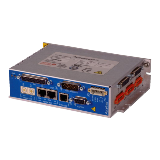
Accelnet & Stepnet Plus Panels User Guide 16-01339 Rev 07 ONNECTOR OCATIONS BEL, BPL, BML C ONNECTOR OCATIONS Front View End View BE2, BP2 C ONNECTOR OCATIONS Front View End View... - Page 74 Accelnet & Stepnet Plus Panels User Guide 16-01339 Rev 07 TEL C ONNECTOR OCATIONS Front View End View TE2, TP2 C ONNECTOR OCATIONS Front View End View...
-
Page 75: Power Connector Locations - Accelnet Models
Accelnet & Stepnet Plus Panels User Guide 16-01339 Rev 07 – A OWER ONNECTOR OCATIONS CCELNET ODELS BEL, BPL, BML, BE2, BP2 - DC P OWER OWER ECEPTACLE Description Euro-style 5.08 mm, 3-position, male receptacle Manufacturer PN Wago: 231-563/108-000 OWER ABLE Description Euro-style 5.08 mm plug... -
Page 76: Bel, Bpl, Be2, Bp2 - Motor Connectors
Accelnet & Stepnet Plus Panels User Guide 16-01339 Rev 07 BEL, BPL, BE2, BP2 - M OTOR ONNECTORS OTOR ECEPTACLE Description Euro-style 5.08 mm, 4-position, male receptacle Manufacturer PN Wago: 231-564/108-000 OTOR ABLE Euro-style, 4 position, 5.08 mm pluggable female terminal Description block Manufacturer PN... -
Page 77: Power Connector Locations - Stepnet Models
Accelnet & Stepnet Plus Panels User Guide 16-01339 Rev 07 – S OWER ONNECTOR OCATIONS TEPNET ODELS TEL, TE2, TP2 - DC P OWER OWER ECEPTACLE Description Euro-style 5.08 mm, 3-position, male receptacle Manufacturer PN Wago: 231-563/108-000 OWER ABLE Description Euro-style 5.08 mm plug Manufacturer PN Wago: 231-303/107-000... -
Page 78: Tel, Te2, Tp2 Motor Connectors
Accelnet & Stepnet Plus Panels User Guide 16-01339 Rev 07 TEL, TE2, TP2 M OTOR ONNECTORS OTOR ONNECTOR OCATIONS OTOR ECEPTACLE Description Euro-style 5.08 mm, 5-position, male receptacle Manufacturer PN Wago: 231-564/108-000 ABLE Description Euro-style, 5 position, 5.08 mm pluggable female terminal block Manufacturer PN Wago: 231-305/107-000 Wire Size... -
Page 79: Motor Brake Connector
Accelnet & Stepnet Plus Panels User Guide 16-01339 Rev 07 OTOR RAKE ONNECTOR BEL, BPL, BML, TEL B RAKE ONNECTOR OCATIONS BEL, BPL, BML,TEL R ECEPTACLE Description Euro-style male receptacle, 3.5 mm,4-position, screw-lock Manufacturer PN Wago MCS-MINI: 734-164/108-000 BEL, BPL,BML,TEL C ABLE Description Euro-style female plug, 3.5 mm,4-position, screw-lock... -
Page 80: Bel, Bpl, Bml,Tel Be2, Bp2, Te2, Tp2
Accelnet & Stepnet Plus Panels User Guide 16-01339 Rev 07 OTOR RAKE ESCRIPTIONS These outputs are open-drain MOSFETs with internal flyback diodes for driving inductive loads. Each can sink up to 1A from a motor brake connected to the +24 Vdc supply. ... -
Page 81: Safe Torque Off
Backshell, D-Sub, RoHS, metallized, #4-40 locking screws Norcomp: 979-009-020R121 ONNECTOR OOLS Note: Th1s part is shown here for convenience. It is not included in connector kits, and is not sold by Copley Controls. Description Manufacturer & PN Insertion/extraction tool for HDP-20 contacts AMP/Tyco 91067-2... - Page 82 Accelnet & Stepnet Plus Panels User Guide 16-01339 Rev 07 ORQUE UTING YPASSING If an application does not require the STO feature, then is can be muted or bypassed by energizing the STO inputs with a power source that is in the Plus Panel drive. And, when the STO feature is not used, these connections must be made in order for the Accelnet &...
-
Page 83: Serial Communications
Accelnet & Stepnet Plus Panels User Guide 16-01339 Rev 07 RS-232 S ERIAL OMMUNICATIONS ONNECTOR OCATIONS BEL, BPL, BML,TEL, BE2, BP2, TE2, TP2 RIVE ONNECTOR 6-position, 4-contact, modular connector (RJ-11 style). ESCRIPTION The RS-232 port connections function as DTE (Data Terminal Equipment) Signal Function No connection... -
Page 84: Network Ports
Accelnet & Stepnet Plus Panels User Guide 16-01339 Rev 07 5.10 N ETWORK ORTS CAT: BEL, BE2, TEL, TE2 THER BEL, BPL, TEL, BE2, BP2, TE2, TP2 ATING ONNECTOR Dual RJ-45 sockets accept standard Ethernet cables and are categorized as 100BASE-TX (100 Mb/sec) ports. Cat 5 or Cat 5e (or higher) cables should be used. - Page 85 Accelnet & Stepnet Plus Panels User Guide 16-01339 Rev 07 CAN B : BPL, BP2, TP2 BEL, BPL, TEL, BE2, BP2, TE2, TP2 ATING ONNECTOR Dual RJ-45 sockets accept standard Ethernet cables for CAN bus communications. Ports are wired pin-to-pin making the IN and OUT ports electrically identical.
-
Page 86: Control I/O
Accelnet & Stepnet Plus Panels User Guide 16-01339 Rev 07 MACRO: BML ATING ONNECTOR Dual SC sockets accept standard optical fiber. The IN port connects to a master, or to the OUT port of a device that is ‘upstream’, between the Accelnet and the master. The OUT port connects to ‘downstream’ nodes. If Accelnet is the last node on a network, only the IN port is used. - Page 87 Accelnet & Stepnet Plus Panels User Guide 16-01339 Rev 07 BE2, BP2, TE2, TP2 S IGNAL ONNECTOR ABLE ONNECTOR Description Manufacturer PN Connector, High-density Dsub DB-44M, 44 position, male, Norcomp: 180-044-103L001 solder-cup, with #4-40 locking screws Backshell, Dsub, RoHS, metallize Norcomp: 979-025-020R121 ESCRIPTIONS Signal...
- Page 88 Accelnet & Stepnet Plus Panels User Guide 16-01339 Rev 07 BE2, BP2, TE2, TP2 I I/O C SOLATED ONNECTOR ABLE ONNECTOR Description Manufacturer PN Connector, High-density Dsub DA-26F, 26 position, female, Norcomp: 180-026-203L001 solder-cup, with #4-40 locking screws Backshell, Dsub, RoHS, metallize Norcomp: 979-015-020R121 ESCRIPTIONS Signal...
- Page 89 Accelnet & Stepnet Plus Panels User Guide 16-01339 Rev 07 NALOG NPUTS The analog inputs have a ±10 Vdc range at 12-bit resolution As reference inputs they can take position/velocity/torque commands from a controller. If not used as command inputs, they can be used as general-purpose analog inputs. NALOG NPUT IRING...
- Page 90 Accelnet & Stepnet Plus Panels User Guide 16-01339 Rev 07 IGITAL NPUTS SOLATED ROGRAMMABLE The input resistor of these inputs is programmable to pull-up to +5V or pull-down to 0V. Pull-up is the default and works with current-sinking outputs from a controller. Pull-down works with current-sourcing outputs, typically PLC’s that drive grounded loads.
- Page 91 Accelnet & Stepnet Plus Panels User Guide 16-01339 Rev 07 : BEL, BPL, BML,TEL SE AS OMMAND NPUTS IGITAL OSITION Command Input S.E. Diff This shows the inputs used with different command input signal formats. Pulse S.E. = Single-Ended /Pulse Diff = Differential /Dir ULSE...
- Page 92 Accelnet & Stepnet Plus Panels User Guide 16-01339 Rev 07 ) & V IGITAL URRENT ORQUE ELOCITY Command Inputs S.E. Diff This shows the inputs used with different PWM 50% command input signal formats. S.E. = Single-Ended /PWM Diff = Differential /Dir PWM / P OLARITY...
- Page 93 Accelnet & Stepnet Plus Panels User Guide 16-01339 Rev 07 : BE2, BP2, TE2, TP2 SE AS OMMAND NPUTS IGITAL OSITION S.E. Multi-Port Command Input This shows the inputs used with Axis A Axis B Axis A Axis B different command input signal Pulse IN12 Enc A...
- Page 94 Accelnet & Stepnet Plus Panels User Guide 16-01339 Rev 07 ) & V URRENT ORQUE ELOCITY S.E. Multi-Port Command This shows the inputs used with Input Axis A Axis B Axis A Axis B different command input signal formats. PWM 50% IN12 Enc A S.E.
- Page 95 Accelnet & Stepnet Plus Panels User Guide 16-01339 Rev 07 IGITAL NPUTS SOLATED These inputs have all the programmable functions of the GP inputs plus opto-isolation. Groups of four inputs, share a Common terminal. Grounding the common terminal configures the group to work with current-sourcing outputs from controllers like PLC’s.
- Page 96 Accelnet & Stepnet Plus Panels User Guide 16-01339 Rev 07 SOLATED UTPUTS These are opto-isolated SSR (Solid-State Relay) outputs, 30 Vdc max. The +/- terminals of each output is accessible, allowing them to act as current sourcing or current sinking devices. There is a Zener clamping diode across each output that acts as a flyback diode when driving resistive-inductive (R-L) loads.
-
Page 97: Multi-Mode Port
Accelnet & Stepnet Plus Panels User Guide 16-01339 Rev 07 5.11.1 M ULTI VERVIEW This port consists of three differential input/output channels (per axis) that take their functions from the Basic Setup of the drive. With quad A/B motor encoder feedback, the port works as an output, buffering the signals from the encoder. - Page 98 Accelnet & Stepnet Plus Panels User Guide 16-01339 Rev 07 ULTI IFFERENTIAL OSITION OMMAND NPUT ONNECTIONS BEL, BPL, BML J1 Pins Input Type Signal Axis-A Pulse(+) Count-Up(+) Quad A Enc A Pulse(-) Count-Up(-) Quad /A Enc /A Dir(+) Count-Down(+) Quad B Enc B Dir(-) Count-Down(-)
- Page 99 Accelnet & Stepnet Plus Panels User Guide 16-01339 Rev 07 Input J1 Pins J1 Pins Type Signal Axis-A Axis-B PWM(+) Enc A PWM(-) Enc /A Dir(+) Enc B Dir(-) Enc /B Signal Ground 6,16,22,31,37,44 ULTI ECONDARY BSOLUTE NCODER NPUTS • 2-Wire: Absolute A •...
- Page 100 Accelnet & Stepnet Plus Panels User Guide 16-01339 Rev 07 • Quad A/B/X Digital Encoders A/B/X E NCODER BEL, BPL, BML Input J1 Pins Type Signal Quad A Enc A Quad /A Enc /A Quad B Enc B Quad /B Enc /B Quad X Enc X...
- Page 101 Accelnet & Stepnet Plus Panels User Guide 16-01339 Rev 07 ULTI UTPUTS • Buffered outputs from primary quad A/B/X encoder inputs • Emulated quad A/B encoder outputs from resolvers or absolute encoder feedback A/B/X UFFERED MULATED BEL, BPL, BML Input J1 Pins Type Signal...
-
Page 102: Motor Feedback
Accelnet & Stepnet Plus Panels User Guide 16-01339 Rev 07 5.12 M OTOR EEDBACK BEL, BPL, BML, BE2, BP2, TEL, TE2, TP2 F EEDBACK ONNECTORS ABLE ONNECTORS Description Manufacturer PN Connector: HDsub DA-26M, male, 26-position plug, solder cup Norcomp: 180-026-103L001 Backshell: HDsub, 26 pin, RoHS, metallized Norcomp: 979-015-020R121 BEL, BPL, TEL... - Page 103 Accelnet & Stepnet Plus Panels User Guide 16-01339 Rev 07 A/B I NCREMENTAL NCODER Condition Example Encoders with differential line-driver outputs Line-line shorts A shorted to /A are required (single-ended encoders are not supported) and provide incremental position Open-circuits: A disconnected, /A connected. feedback via the A/B signals and the optional Terminator resistor pulls A &...
- Page 104 Accelnet & Stepnet Plus Panels User Guide 16-01339 Rev 07 ESOLVER OPTION Connections to the resolver should be made with shielded cable that uses three twisted-pairs. Once connected, resolver set up, motor phasing, and other commissioning adjustments are made with CME software. There are no hardware adjustments.
- Page 105 Accelnet & Stepnet Plus Panels User Guide 16-01339 Rev 07 SSI A BSOLUTE NCODER The SSI (Synchronous Serial Interface) is an interface used to connect an absolute position encoder to a motion controller or control system. The drive provides a train of clock signals in differential format to the encoder which initiates the transmission of the position data on the subsequent clock pulses.
- Page 106 Accelnet & Stepnet Plus Panels User Guide 16-01339 Rev 07 BSOLUTE NCODER The EnDat interface is a Heidenhain interface that is similar to SSI in the use of clock and data signals, but which also supports analog sin/cos channels from the same encoder. The number of position data bits is programmable as is the use of sin/cos channels.
- Page 107 Accelnet & Stepnet Plus Panels User Guide 16-01339 Rev 07 ALLS Hall signals are single-ended signals that provide absolute feedback within one electrical cycle of the motor. There are three of them (U, V, & W) and they may be sourced by magnetic sensors in the motor, or by encoders that have Hall tracks as part of the encoder disc.
-
Page 108: Appendix
Accelnet & Stepnet Plus Panels User Guide 16-01339 Rev 07 PPENDIX IMIT LGORITHM The current loop I T limit specifies the maximum amount of time that the peak current can be applied to the motor before it must be reduced to the continuous limit or generate a fault. This chapter describes the algorithm used to implement the I T limit. - Page 109 Accelnet & Stepnet Plus Panels User Guide 16-01339 Rev 07 – A URRENT IMIT LGORITHM PPLICATION XAMPLE XAMPLE ARAMETERS Operation of the I T current limit algorithm is best understood through an example. For this example, a motor with the following characteristics is used: •...
-
Page 110: B: Connecting Bpl/Bp2/Tp2 For Serial Control
Accelnet & Stepnet Plus Panels User Guide 16-01339 Rev 07 BPL/BP2/TP2 ONNECTING ERIAL ONTROL This chapter describes how to connect one or more BPL/BP2/TP2 drives for control via the RS-232 bus on one of the drives. INGLE XIS AND ULTI A BPL/BP2/TP2 drive’s RS-232 serial bus can be used by CME for drive commissioning. -
Page 111: C: Ordering Guide And Accessories
Accelnet & Stepnet Plus Panels User Guide 16-01339 Rev 07 RDERING UIDE AND CCESSORIES This chapter lists part numbers for drives and accessories. Contents include: BEL M ODEL UMBERS Model Number Description BEL-090-06 Accelnet Plus EtherCAT Servo drive 3/6 A, encoder feedback Accelnet Plus EtherCAT Servo drive 3/6 A, encoder feedback, BEL-090-06-H with factory-fitted heatsink... - Page 112 Accelnet & Stepnet Plus Panels User Guide 16-01339 Rev 07 BE2 M ODEL UMBERS Model Number Description BE2-090-06 Accelnet Plus EtherCAT 2-Axis Servo drive 3/6 A, encoder feedback Accelnet Plus EtherCAT 2-Axis Servo drive 3/6 A, encoder feedback, BE2-090-06-H with factory-fitted heatsink BE2-090-06-R Accelnet Plus EtherCAT 2-Axis Servo drive 3/6 A resolver feedback Accelnet Plus EtherCAT 2-Axis Servo drive 3/6 A resolver feedback...
- Page 113 Accelnet & Stepnet Plus Panels User Guide 16-01339 Rev 07 BPL M ODEL UMBERS Model Number Description BPL-090-06 Accelnet Plus CANopen Servo drive 3/6 A, encoder feedback Accelnet Plus CANopen Servo drive 3/6 A, encoder feedback, BPL-090-06-H with factory-fitted heatsink BPL-090-06-R Accelnet Plus CANopen Servo drive 3/6 A resolver feedback Accelnet Plus CANopen Servo drive 3/6 A resolver feedback,...
- Page 114 Accelnet & Stepnet Plus Panels User Guide 16-01339 Rev 07 BP2 M ODEL UMBERS Model Number Description BP2-090-06 Accelnet Plus CANopen 2-Axis Servo drive 3/6 A, encoder feedback Accelnet Plus CANopen 2-Axis Servo drive 3/6 A, encoder feedback, BP2-090-06-H with factory-fitted heatsink BP2-090-06-R Accelnet Plus CANopen 2-Axis Servo drive 3/6 A resolver feedback Accelnet Plus CANopen 2-Axis Servo drive 3/6 A resolver feedback...
- Page 115 Accelnet & Stepnet Plus Panels User Guide 16-01339 Rev 07 TEL M ODEL UMBERS Model Number Description TEL-090-07 Stepnet Plus EtherCAT Stepper drive 5/7 A, encoder feedback Stepnet Plus EtherCAT Stepper drive 5/7 A, encoder feedback, TEL-090-07-H with factory-fitted heatsink TEL-090-10 Stepnet Plus EtherCAT Stepper drive 10/10 A, encoder feedback Stepnet Plus EtherCAT Stepper drive 10/10 A, encoder feedback,...
- Page 116 Accelnet & Stepnet Plus Panels User Guide 16-01339 Rev 07 CCESSORIES BEL C ONNECTOR Label Description Manufacturers Part Number Connector, high-density HD-Sub, Norcomp: 180-044-103L001 44 position, male, solder cup Control Backshell, HD-Sub, 44 Pin, RoHS, Norcomp: 979-025-020R121 metallized Connector, D-Sub, 9-position, AMP/Tyco: 205204-4 standard AMPLIMITE HDP-20 Crimp-Snap...
- Page 117 Accelnet & Stepnet Plus Panels User Guide 16-01339 Rev 07 BPL C ONNECTOR Label Description Manufacturers Part Number Connector, high-density HD-Sub, Norcomp: 180-044-103L001 44 position, male, solder cup Control Backshell, HD-Sub, 44 Pin, RoHS, Norcomp: 979-025-020R121 metallized Connector, D-Sub, 9-position, AMP/Tyco: 205204-4 standard AMPLIMITE HDP-20 Crimp-Snap...
- Page 118 Accelnet & Stepnet Plus Panels User Guide 16-01339 Rev 07 BML C ONNECTOR Label Description Manufacturers Part Number Connector, high-density HD-Sub, Norcomp: 180-044-103L001 44 position, male, solder cup Control Backshell, HD-Sub, 44 Pin, RoHS, Norcomp: 979-025-020R121 metallized Connector, D-Sub, 9-position, AMP/Tyco: 205204-4 standard AMPLIMITE HDP-20 Crimp-Snap...
- Page 119 Accelnet & Stepnet Plus Panels User Guide 16-01339 Rev 07 BE2 C ONNECTOR Label Description Manufacturers Part Number Connector, high-density HD-Sub, 44 position, Norcomp: 180-044-103L001 male, solder cup Control Backshell, HD-Sub, 44 Pin, Norcomp: 979-025-020R121 RoHS, metallized Connector, high-density HD-Sub, 26 position, female, Norcomp: 180-026-203L001 solder cup Plug 3.5 mm, screw-lock,...
- Page 120 Accelnet & Stepnet Plus Panels User Guide 16-01339 Rev 07 BP2 C ONNECTOR Label Description Manufacturers Part Number Connector, high-density HD-Sub, 44 position, male, Norcomp: 180-044-103L001 solder cup Control Backshell, HD-Sub, 44 Pin, Norcomp: 979-025-020R121 RoHS, metallized Connector, high-density HD-Sub, 26 position, female, Norcomp: 180-026-203L001 solder cup Plug 3.5 mm, screw-lock, 5...
- Page 121 Accelnet & Stepnet Plus Panels User Guide 16-01339 Rev 07 BP2 CAN OPEN ONNECTOR Model Description BPL-CV: Sub-D 9-position female to RJ-45 adapter BP2-NK BPL-NC:-10 CAN bus Network Cable, 10 ft (3 m) BPL-NT: CAN bus RJ-45 Network Terminator BP2 I NDIVIDUAL ABLE SSEMBLIES...
- Page 122 Accelnet & Stepnet Plus Panels User Guide 16-01339 Rev 07 Tool Tool, wire insertion & extraction Wago: 231-159 Note 1: For RoHS compliance, append “/RN01-0000” to the Wago part numbers listed above. NDIVIDUAL ABLE SSEMBLIES ELATED CCESSORIES Model Description TEL-SK RS-232 Cable Kit: Dsub-9 molded cable with plug for J2 TEL-NC-10 EtherCAT Network Cable, 10 ft (3 m)
- Page 123 Accelnet & Stepnet Plus Panels User Guide 16-01339 Rev 07 Note 1: For RoHS compliance, append “/RN01-0000” to the Wago part numbers listed above. NDIVIDUAL ABLE SSEMBLIES ELATED CCESSORIES Model Description SER-SK RS-232 Serial Cable Kit (for connecting PC to drive) TE2-NC-10 EtherCAT Network Cable, 10 ft (3 m) TE2-NC-01...
- Page 124 Accelnet & Stepnet Plus Panels User Guide 16-01339 Rev 07 TP2 CAN OPEN ONNECTOR Model Description BPL-CV: Sub-D 9-position female to RJ-45 adapter TP2-NK BPL-NC:-10 CAN bus Network Cable, 10 ft (3 m) BPL-NT: CAN bus RJ-45 Network Terminator TP2 I NDIVIDUAL ABLE SSEMBLIES...
- Page 125 Accelnet & Stepnet Plus Panels User Guide 16-01339 Rev 07 Accelnet & Stepnet Plus Panels User Guide P/N: 16-01339 Revision 07 September 16, 2021 Copley Controls 20 Dan Road Canton, MA 02021 USA All rights reserved © 2021...
Need help?
Do you have a question about the Accelnet Plus BEL Series and is the answer not in the manual?
Questions and answers