Table of Contents

Subscribe to Our Youtube Channel
Related Manuals for ADLINK Technology ROScube-I Series


Summary of Contents for ADLINK Technology ROScube-I Series
- Page 1 ROScube-I Series Embedded Real-Time Robotic Controller with Intel® Xeon®/Core™ Processor RQI-58/57/55/53, RQI-58-E/57-E/55-E/53-E User’s Manual Manual Rev.: December 18, 2020 Revision Date: 50-1Z314-1020 Part No: Leading EDGE COMPUTING...
- Page 2 Leading EDGE COMPUTING Revision History Revision Release Date Description of Change(s) 2020-07-15 Initial release Updated section 4 and Appendix D; Updated 2020-09-04 Important Safety Information and warning and caution notes in Appendix B Updated CANbus module info, AC/DC adapter P/N, airflow info, power source requirements; 2020-12-18 added wall mounting note;...
-
Page 3: Preface
ROScube-I Series Preface Copyright © 2020 ADLINK Technology Inc. This document contains proprietary information protected by copy- right. All rights are reserved. No part of this manual may be repro- duced by any mechanical, electronic, or other means in any form without prior written permission of the manufacturer. - Page 4 Leading EDGE COMPUTING California Proposition 65 Warning WARNING: This product can expose you to chemicals including acrylamide, arsenic, benzene, cadmium, Tris(1,3-dichloro-2-propyl) phosphate (TDCPP), 1,4- Dioxane, formaldehyde, lead, DEHP, styrene, DINP, BBP, PVC, and vinyl materials, which are known to the State of California to cause cancer, and acrylamide, benzene, cadmium, lead, mercury, phthalates, toluene, DEHP, DIDP, DnHP, DBP, BBP, PVC, and vinyl materials, which are known to the State of California to cause...
-
Page 5: Table Of Contents
Packing List ................. 1 Optional Accessories ............2 2 Specifications ..............3 RQI-58(-E), RQI-57(-E)............3 RQI-55(-E), RQI-53(-E)............6 ROScube-I Series Functional Block Diagram...... 9 Display Options..............10 Mechanical Dimensions............. 11 3 System Layout..............15 Front Panel ................ 15 Internal I/O Connectors............27 4 Getting Started .............. - Page 6 Leading EDGE COMPUTING B Appendix: BIOS Setup............39 Main ................... 40 Advanced ................41 Chipset................56 Security ................65 Boot ................... 67 Save & Exit ................ 69 C Appendix: Watchdog Timer ..........71 WDT with Linux..............71 D Appendix: I/O Operation............73 DI/O ................... 73 I2C ..................
-
Page 7: List Of Tables
ROScube-I Series List of Tables Table 2-1: Maximum Display Resolution Configurations ... 10 Table 3-1: Front Panel I/O Legend ..........15 Table 3-2: Front Panel I/O - Expansion Box Legend ....16 Table 3-3: DisplayPort Pin Definition ......... 18 Table 3-4: Applicable Cable Types.......... - Page 8 Leading EDGE COMPUTING This page intentionally left blank. viii List of Tables...
-
Page 9: List Of Figures
ROScube-I Series List of Figures Figure 2-1: ROScube-I Series Functional Block Diagram....9 Figure 2-2: ROScube-I Series Top View.......... 11 Figure 2-3: ROScube-I Series Side View......... 12 Figure 2-4: ROScube-I Series Front View........13 Figure 3-1: Front Panel I/O .............. 15 Figure 3-2: Front Panel I/O - Expansion Box ........ - Page 10 Leading EDGE COMPUTING This page intentionally left blank. List of Figures...
-
Page 11: Introduction
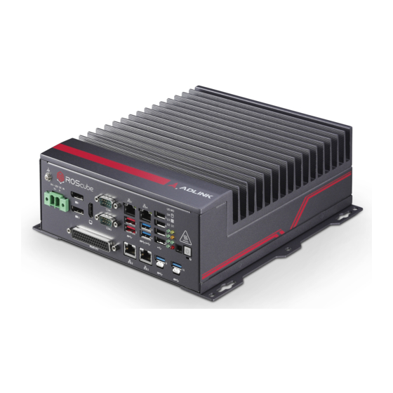
ROScube-I Series Introduction 1.1 Overview The ADLINK ROScube-I Series Embedded Real-Time Robotic ® ® Controller is powered by the Intel Xeon /Core™ processor, and features exceptional I/O connectivity enabling a wide variety of sensors and actuators for unlimited robotic applications. Also sup- ®... -
Page 12: Optional Accessories
Leading EDGE COMPUTING 1.4 Optional Accessories AC/DC Adapter 160W (P/N: 31-62120-0010) 220W (P/N: 31-62149-0000) 280W (P/N: 31-62162-1010-A0, for “E” expansion box models) Wi-Fi Module: Intel® Wireless-AC9260 M.2 2230, Dual- Band 2x2 Wi-Fi + Bluetooth 5 kit (P/N: TBD) CANbus Module: Dual channel: FARO-FP900 (P/N: 92-97142-0020) DDR4 SO-DIMM Memory 8 GB DDR4 2400 MHz Dual Channel non-ECC memory... -
Page 13: Specifications
ROScube-I Series Specifications 2.1 RQI-58(-E), RQI-57(-E) RQI-58(-E) RQI-57(-E) System Core Processor Intel® Xeon® E-2276ME 45W Intel® Core™ i7-9850HE 45W Cores Base Freq. 2.8 GHz 2.7 GHz MAX Turbo 4.5 GHz 4.4 GHz Freq. Chipset Mobile Intel® CM246 Memory 32GB DDR4 2400MHz installed, dual SODIMMs... - Page 14 Leading EDGE COMPUTING RQI-58(-E) RQI-57(-E) Storage M.2 B Key or 256GB mSATA SSD B+M Key PCIe Expansion (“E” models w/ expansion box only) 1x PCIe x16 Gen3 PCIe Slots 1x PCIe x4 Gen3 Physical Standard: 210 (W) x 240 (D) x 86 (H) mm (8.27" x 9.45" x 3.39") Dimensions “E”...
- Page 15 ROScube-I Series RQI-58(-E) RQI-57(-E) Environmental (cont’d) IEC 61000-4-2 (ESD, contact: ±8kV, air: ±15kV) IEC 61000-4-3 (RS, 10V/m from 80-1000MHz, 3V/m from 1400- 2000MHz, 1V/m from 2000-2700MHz, 1kHZ sine wave, 80% AM) IEC 61000-4-4 (EFT, ±2kV at 5KHz on power port, ±1kV at 5KHz on signal port) IEC 61000-4-5 (Surge, ±2kV line to earth CM on power port,...
-
Page 16: Rqi-55(-E), Rqi-53(-E)
Leading EDGE COMPUTING 2.2 RQI-55(-E), RQI-53(-E) RQI-55(-E) RQI-53(-E) System Core Processor Intel® Core™ i5-8400H 45W Intel® Core™ i3-9100HL 25W Cores Base Freq. 2.5 GHz 1.6 GHz MAX Turbo 4.2 GHz 2.9 GHz Freq. Chipset Mobile Intel® CM246 16GB DDR4 2400MHz installed, 8GB DDR4 2400MHz installed, Memory single SODIMM (max 32GB) - Page 17 ROScube-I Series RQI-55(-E) RQI-53(-E) Storage M.2 B Key or 128GB mSATA SSD 64GB mSATA SSD B+M Key PCIe Expansion (“E” models w/ expansion box only) 1x PCIe x16 Gen3 PCIe Slots 1x PCIe x4 Gen3 Physical Standard: 210 (W) x 240 (D) x 86 (H) mm (8.27" x 9.45" x 3.39") Dimensions “E”...
- Page 18 Leading EDGE COMPUTING RQI-55(-E) RQI-53(-E) Environmental (cont’d) IEC 61000-4-2 (ESD, contact: ±8kV, air: ±15kV) IEC 61000-4-3 (RS, 10V/m from 80-1000MHz, 3V/m from 1400- 2000MHz, 1V/m from 2000-2700MHz, 1kHZ sine wave, 80% AM) IEC 61000-4-4 (EFT, ±2kV at 5KHz on power port, ±1kV at 5KHz on signal port) IEC 61000-4-5 (Surge, ±2kV line to earth CM on power port, ±1kV line to earth CM on signal port)
-
Page 19: Roscube-I Series Functional Block Diagram
Mini PCIe COM2 232 USB 2.0 PCH CM246 PCIe x1 Mini PCIe PCIe USB 2.0 USB 3.1 PCIe x1 CONN I2C0 Wafer USB 2.0 I2C1 TPM 2.0 Wafer Wafer Connector AFM Board Figure 2-1: ROScube-I Series Functional Block Diagram Specifications... -
Page 20: Display Options
Leading EDGE COMPUTING 2.4 Display Options With computing and graphic performance enhancement from its 8th and 9th Generation Intel® processors, the ROScube-I Series controller can support three independent displays in the following configurations. Port Resolution DisplayPort1 4096x2304@60Hz Display Option 1... -
Page 21: Mechanical Dimensions
ROScube-I Series 2.5 Mechanical Dimensions R2.6 units: mm Figure 2-2: ROScube-I Series Top View Specifications... -
Page 22: Figure 2-3: Roscube-I Series Side View
Leading EDGE COMPUTING Standard: Expansion: units: mm Figure 2-3: ROScube-I Series Side View Specifications... -
Page 23: Figure 2-4: Roscube-I Series Front View
ROScube-I Series Standard: Expansion: units: mm Figure 2-4: ROScube-I Series Front View Specifications... - Page 24 Leading EDGE COMPUTING This page intentionally left blank. Specifications...
-
Page 25: System Layout
ROScube-I Series System Layout 3.1 Front Panel The ROScube-I Series provides the following front panel access features. Figure 3-1: Front Panel I/O DC Power Supply H LED Indicators DisplayPort x2 Extend Power Button Connector HDMI Connector J Power Button COM Port x2 K Multi-I/O port USB 3.1 Type-A x4... -
Page 26: Table 3-2: Front Panel I/O - Expansion Box Legend
Leading EDGE COMPUTING The ROScube-I Series “E” models with expansion box provide two PCI Express expansion slots. Figure 3-2: Front Panel I/O - Expansion Box PCIe x16 slot (max. power 75W) PCIe x4 slot (max. power 25W) Table 3-2: Front Panel I/O - Expansion Box Legend 3.1.1... - Page 27 ROScube-I Series 3.1.2 LED Indicators In addition to the power button, eight LEDs on the front panel indi- cate the following. LED Indicator Color Description Indicates watchdog timer status. When watchdog Watchdog Yellow timer starts, the LED flashes. When the timer is (WD) expired, the system will auto reboot.
-
Page 28: Table 3-3: Displayport Pin Definition
Leading EDGE COMPUTING adapter cable, DisplayPort to DVI adapter cable, or DisplayPort to HDMI adapter cable and DisplayPort cable. Signal Signal CN_DDPx0+ 11 CN_DDPx3- CN_DDPx0- CN_DDPx_AUX_SEL CN_DDPx1+ 14 CN_DDPx_CONFIG2 CN_DDPx_AUX+ CN_DDPx1- CN_DDPx2+ 17 CN_DDPx_AUX- CN_DDPx_HPD CN_DDPx2- CN_DDPx3+ 20 +V3.3_DDPx_PWR_CN Table 3-3: DisplayPort Pin Definition Description 30-01119-0010 Active DisplayPort to HDMI adapter cable... -
Page 29: Table 3-5: Multi-I/O Db-50 Connector Pin Definition
ROScube-I Series 8-channel Digital Input VIH: 2 to 5.25V VIL: 0 to 0.8V 8-channel Digital Output Output type: Open drain N-channel MOSFET driver with internal pull high of 200Ω resistance. Source/Sink current for all channels: 24mA VOH: 2.4 to 5V VOL: 0 to 0.5V... -
Page 30: Figure 3-3: Digital Input Circuit
Leading EDGE COMPUTING Figure 3-3: Digital Input Circuit Figure 3-4: Digital Output Circuit System Layout... -
Page 31: Table 3-6: Canbus Module Support Table
ROScube-I Series CANbus By default, a CANbus module is not installed on the system. Tested module types and vendor information are listed in the table below. The PEAK CANbus module has been integrated into our RTOS software and this module can be selected for real-time systems. -
Page 32: Table 3-8: Hdmi Connector Pin Definition
Leading EDGE COMPUTING 3.1.6 HDMI Connector The ROScube-I Series provides one HDMI connector for connec- tion to an external monitor. Pin # Signal Pin # Signal TMDS Data2+ TMDS Data2 Shield TMDS Data2– TMDS Data1+ TMDS Data1 Shield TMDS Data1–... - Page 33 ROScube-I Series 3.1.8 USB 3.1 Ports The ROScube-I provides 2x USB 3.1 Gen1 Type A lockable ports and 4x USB 3.1 Gen1 Type A standard ports on the front panel. All USB 3.1 ports are compatible with SuperSpeed Gen1, high- speed, full speed, and low-speed USB device.
-
Page 34: Table 3-9: Ethernet Port Pin Definition
Leading EDGE COMPUTING 10BASE-T/ Pin # 1000BASE-T 100BASE-TX LAN_TX0+ LAN_TX0- LAN_TX1+ — LAN_TX2+ — LAN_TX2- LAN_TX1- — LAN_TX3+ — LAN_TX3- Table 3-9: Ethernet Port Pin Definition Speed LED Active/Link Green/Orange Yellow Figure 3-5: Ethernet Port and LEDs LED Color Status Description Ethernet port is disconnected. -
Page 35: Table 3-12: Dc Power Input Pin Definition
ROScube-I Series 3.1.10 DC Power Input Figure 3-6: DC Power Input Signal V+ (DC_IN) V- (DGND) Table 3-12: DC Power Input Pin Definition Refer to Section 4.1: Attaching the DC Power Connector on page 33 to install the DC Power Connector to the DC Power Input. -
Page 36: Table 3-13: Com Port D-Sub 9-Pin Signal Functions
Leading EDGE COMPUTING Before providing DC power, ensure the voltage and polarity pro- vided are compatible with the DC input. Improper input voltage and/or polarity can be responsible for system damage. WARNING: AVERTISSEMENT: Avant de fournir une alimentation CC, assurez-vous que la tension et la polarité fournies sont compati- bles avec l'entrée CC. -
Page 37: Internal I/O Connectors
ROScube-I Series 3.2 Internal I/O Connectors 3.2.1 Board Layout Function Module Mainboard Figure 3-8: Board Layout System Layout... -
Page 38: Table 3-14: Mainboard Connector Legend
Leading EDGE COMPUTING 3.2.2 Mainboard Connector Locations Figure 3-9: Mainboard Connectors Fan connector C1 connector USB 2.0 dongle Power and Reset header Backplane slot C0 connector Backplane slot COM port 3 and 4 connectors M.2 connector (for storage) DIO, COM port 5/6, Audio connector DDR4 SO-DIMM slot Speaker connector SIM card socket for Mini PCIe... -
Page 39: Table 3-15: Function Module Connector Legend
ROScube-I Series 3.2.3 Function Module Connector Locations Figure 3-10: Function Module Connectors USB 3.1 Gen 1 lockable connector USB 3.1 Gen 1 lockable connector Gigabit RJ-45 port Gigabit RJ-45 port Multi-I/O DB 50-pin connector CANbus connector (CN3) Fan connector M.2 A+E Key connector (CN4) -
Page 40: Table 3-16: Gps Module Power Header Pin Definition
Leading EDGE COMPUTING 3.2.4 GPS Module Power Header Power supply via cable for Mini PCIe GPS module card (5V). Figure 3-11: GPS Module Power Header Pin Definition Signal +5V_GPS Table 3-16: GPS Module Power Header Pin Definition 3.2.5 USB 2.0 Connector One USB 2.0 Type-A connector is provided on the mainboard for internal USB dongle, with another on the PCIe expansion slot riser card. -
Page 41: Table 3-17: Power/Reset Header Pin Definition
ROScube-I Series 3.2.8 Extended Power/Reset Header An internal header is provided for the Power and Reset buttons, with pin definition as shown. Figure 3-13: PWR/RESET Header Pin Definition Signal PWR_BTN-L RESET_BTN-L Table 3-17: Power/Reset Header Pin Definition 3.2.9 SIM Card Socket The SIM card socket connects to the Mini PCIe slot on the main- board. - Page 42 Leading EDGE COMPUTING This page intentionally left blank. System Layout...
-
Page 43: Getting Started
ROScube-I Series Getting Started This chapter describes how to set up and install the ROScube-I Series. 4.1 Attaching the DC Power Connector Locate the DC power connector shown below that is included in the accessory box. Insert the power connector into DC power input “A”... -
Page 44: Mounting The Roscube-I Series
Leading EDGE COMPUTING 4.2 Mounting the ROScube-I Series 4.2.1 Install the Wall-mount Brackets Use the 6x M4 6mm screws included in the accessory box to attach the 2 included wall-mount brackets to the chassis as indi- cated by the red circles below. - Page 45 Figure 2-2 ROScube-I Series Top View. Montez l'appareil sur un mur à l'aide des 4 ouvertures de trou de serrure en fonction des dimensions d'espacement des trous dans le support, comme indiqué dans Figure 2-2 ROScube-I Series Top View. keyhole keyhole...
- Page 46 Leading EDGE COMPUTING This page intentionally left blank. Getting Started...
-
Page 47: A Appendix: Power
ROScube-I Series Appendix A Power Information in this Appendix is for power budget planning and design purposes only. Actual power consumption may differ based on final application. NOTE: NOTE: A.1 Power Consumption Reference Power consumption as follows is based on lab data in which 24V DC is applied and current is measured by the DC power supply. - Page 48 Leading EDGE COMPUTING Sufficient power supply for the entire system is required to meet these specifications. At least 100W at 24V input is recommended. NOTE: NOTE: Heat generated by add-on PCI/PCIe adapters affects thermal stability. Additional heat dissipa- tion is required when the system operates at high temperatures or in harsh environments with add-on adapters.
-
Page 49: B Appendix: Bios Setup
ROScube-I Series. Most users do not need to use the BIOS setup program, as the ROScube-I Series ships with default settings that work well for most configurations. Enter BIOS setup by selecting DEL when the system is powered on the POST (Power On Self Test) message is displayed.The... -
Page 50: Main
Leading EDGE COMPUTING B.1 Main Contains basic system information for the ROScube-I Series. Changing BIOS settings may lead to incorrect controller behav- ior and possible inability to boot. In such a case, Section 3.2.7:Clear CMOS Jumper provides instruction on WARNING: clearing the CMOS and restoring default settings. -
Page 51: Advanced
NOTE: appears as 05:30:00, and 5:30 P.M. as 17:30:00. B.2 Advanced Accesses advanced options of the ROScube-I Series. Setting incorrect or conflicting values in Advanced BIOS Setup may cause a system malfunction. MISE EN GARDE: L'application de valeurs incorrectes ou con- CAUTION: tradictoires dans la configuration avancée du BIOS peut... - Page 52 Leading EDGE COMPUTING B.2.1 CPU Configuration BIOS Setup...
- Page 53 ROScube-I Series Hyper-Threading Enabled for Windows 7, 10 IoT Enterprise, and Linux (optimized for Hyper-Threading Technology). When Disabled only one thread per enabled core is enabled. Active Processor Cores Number of cores to enable in each processor package. Intel (VMX) Virtualization Technology When enabled, a VMM can utilize the additional hardware capabil- ities provided by Vanderpool Technology.
- Page 54 Leading EDGE COMPUTING B.2.2 Power Management State After G3 Specify what state to go to when power is re-applied after a power failure (G3 state). RTC Wake system from S5 Enables/Disables the system wake on alarm event. Select Fixed- Time, and the system will wake on the hr::min::sec specified. Select DynamicTime, the system will wake on the current time + Increase minute(s).
- Page 55 ROScube-I Series B.2.3 Serial Console Configuration COM1 Console Redirection Enables/Disables SIO COM1 Console Redirection. Console Redirection Settings The settings specify how the host computer and the remote com- puter (which the user is using) will exchange data. Both computers should have the same or compatible settings.
- Page 56 Leading EDGE COMPUTING Console Redirection Settings The settings specify how the host computer and the remote com- puter (which the user is using) will exchange data. Both computers should have the same or compatible settings. COM SOL (Pci Bus0, Dev22.Fun3) Console Redirection Enables/Disables AMT PCI SOL Console Redirection.
- Page 57 ROScube-I Series B.2.4 USB Configuration USB Mass Storage Driver Support Enables/Disables USB mass storage driver support. USB transfer time-out Timeout value for Control, Bulk, and Interrupt transfers. Device reset time-out USB mass storage device Start Unit command timeout. Device power-up delay...
- Page 58 Leading EDGE COMPUTING B.2.5 TPM 2.0 Configuration Security Device Support Enables/Disables BIOS support for security devices. The operat- ing system will not show the security device. The TCG EFI proto- col and INT1A interface will not be available. SHA-1 PCR Bank Enables/Disables SHA-1 PCR Bank.
- Page 59 ROScube-I Series Pending operation Schedule an operation for the security device. The computer will reboot in order to change the state of the security device NOTE: NOTE: Platform Hierarchy Enables/Disables Platform Hierarchy. Storage Hierarchy Enables/Disables Storage Hierarchy. Endorsement Hierarchy Enables/Disables Endorsement Hierarchy.
- Page 60 Leading EDGE COMPUTING B.2.6 AMT Configuration AMT BIOS Features When disabled, AMT BIOS Features are no longer supported and the user is no longer able to access MEBx Setup. MEBx hotkey Pressed Enable automatic MEBx hotkey press. BIOS Setup...
- Page 61 ROScube-I Series B.2.7 Onboard Devices Configuration COM1 Control Sets port type (RS-232/422/485) for COM1 serial port. COM2 Control Sets port type (RS-232/422/485) for COM2 serial port. LAN #1 (Intel I219) Enables/Disables onboard Intel I219 LAN controller. LAN #2 (Intel I211AT) Enables/Disables onboard Intel I211AT LAN controller.
- Page 62 Leading EDGE COMPUTING B.2.8 NCT6106D HW Monitor NCT6106D HW Monitor Displays CPU/board temperatures, system fan speed and various voltages. System Fan Control Mode Sets the system fan control mode. T1 (Temperature 1), Range: 1-100 T1 Duty Set T1 related DC/PWM value, Range: 0-255 T2 (Temperature 2), Range: 1-100 BIOS Setup...
- Page 63 ROScube-I Series T2 Duty Set T2 related DC/PWM value, Range: 0-255 T3 (Temperature 3), Range: 1-100 T3 Duty Set T3 related DC/PWM value, Range: 0-255 T4 (Temperature 4), Range: 1-100 T4 Duty Set T4 related DC/PWM value, Range: 0-255 BIOS Setup...
- Page 64 Leading EDGE COMPUTING B.2.9 BIOS Watchdog Timer BIOS POST Watchdog Disable: Disables watchdog timer. Second Mode: Enables watchdog timer in seconds mode. Minute Mode: Enables watchdog timer in minutes mode. BIOS Setup...
- Page 65 ROScube-I Series B.2.10 Network Stack Configuration Network Stack Enables/Disables UEFI network stack. BIOS Setup...
-
Page 66: Chipset
Leading EDGE COMPUTING B.3 Chipset Setting incorrect or conflicting values in Chipset BIOS Setup may cause a system malfunction. MISE EN GARDE: L'application de valeurs incorrectes ou con- CAUTION: tradictoires dans la configuration du BIOS du chipset peut entraîner un dysfonctionnement du système. BIOS Setup... - Page 67 ROScube-I Series B.3.1 System Agent (SA) Configuration System Agent (SA) Configuration Display and configure VT-d's capability and provide settings for memory, graphics and DMI/OPI configuration. BIOS Setup...
- Page 68 Leading EDGE COMPUTING B.3.1.1 Memory Configuration Memory Configuration Display memory speed, size, brand and configuration. BIOS Setup...
- Page 69 ROScube-I Series B.3.1.2 Graphics Configuration Internal Graphics Keep IGFX enabled based on the Setup options. GTT Size Sets GTT size. Aperture Size Sets aperture size. DVMT Pre-Allocated Sets size of DVMT 5.0 pre-allocated (fixed) graphics memory used by the internal graphics device.
- Page 70 Leading EDGE COMPUTING DVMT Total Gfx Mem Sets size of DVMT5.0 total graphic memory used by the internal graphics device. B.3.1.3 DMI/OPI Configuration DMI/OPI Configuration Display DMI link speed and width. DMI Max Link Speed Set sDMI speed to Gen1/Gen2/Gen3. BIOS Setup...
- Page 71 ROScube-I Series B.3.2 PCH-IO Configuration PCH-IO Configuration Provides for SATA, Security and HD Audio configuration. BIOS Setup...
- Page 72 Leading EDGE COMPUTING B.3.2.1 SATA And RST Configuration SATA Mode Selection Determines how SATA controller(s) operate. SATA Controller Speed Sets the maximum speed the SATA controller can support. M.2 Storage Enables/Disables M.2 storage. CFast Card Enables/Disables CFast card. Hot Plug Designates selected port as hot pluggable.
- Page 73 ROScube-I Series SATA HDD 1 Enables/Disables SATA HDD 1 SATA HDD 2 Enables/Disables SATA HDD 2 B.3.2.2 Security Configuration BIOS Lock Enable/Disable the PCH BIOS Lock Enable feature. Required to be enabled to ensure SMM protection of flash. BIOS Setup...
- Page 74 Leading EDGE COMPUTING B.3.2.3 HD Audio Configuration Audio Output Selection Selects the audio output device. BIOS Setup...
-
Page 75: Security
ROScube-I Series B.4 Security If only the Administrator password is set, access s limited and the password requested on Setup. If User password is set, it acts as a power-on password and must be entered to boot or enter setup. In... - Page 76 Leading EDGE COMPUTING B.4.1 Secure Boot Menu Secure Boot Control The Secure Boot feature is Active if Secure Boot is enabled, Plat- form Key (PK) is enrolled and the system is in User mode. Chang- ing the system mode requires a platform reset. BIOS Setup...
-
Page 77: Boot
ROScube-I Series B.5 Boot Setup Prompt Timeout Number of seconds before setup activation key is launched, with 65535(0xFFFF) setting an indefinite wait time. Bootup Num-Lock State Sets keypad Number Lock status following boot. Quiet Boot Option Description Disabled Directs BIOS to display POST messages Enabled Directs BIOS to display the OEM logo. - Page 78 Leading EDGE COMPUTING Fast Boot Option Description Disabled Directs BIOS to perform all POST tests. Directs BIOS to skip certain POST tests to boot Enabled faster. While enabling Fast Boot can reduce system ready time, some prerequisites can reduce effectiveness Boot mode select Sets legacy or UEFI boot mode.
-
Page 79: Save & Exit
ROScube-I Series B.6 Save & Exit Save Changes and Exit Saves all changes before exiting Setup. Discard Changes and Exit Discards all changes and exits Setup. Save Changes and Reset Saves all changes and reboots the system with the new settings. - Page 80 Leading EDGE COMPUTING Discard Changes Discards all changes without exiting Setup. Restore Defaults Sets all BIOS options to default settings, designed for maximum system stability but less than maximum performance. Select Restore Defaults if the computer encounters system configuration problems. Save as User Defaults Save the current changes as user defaults.
-
Page 81: C Appendix: Watchdog Timer
Appendix C Watchdog Timer This appendix describes use of the watchdog timer (WDT) for the ROScube-I Series controller. The Watchdog Timer (WDT) on Linux is used to monitor if a system is still running. It is designed to reboot a hung system automatically. - Page 82 Leading EDGE COMPUTING 2. Start and set the WTD to 60 seconds by using: sudo modprobe w83627hf_wdt timeout=60 After starting the WTD using this command, you need to reset the WTD continuously, or the system will reboot in 60 seconds. 3.
-
Page 83: D Appendix: I/O Operation
ROScube-I Series Appendix D I/O Operation The ROScube-I Series supports several Linux-based Neuron libraries for interfaces such as DI/O and I2C. ADLINK provides function libraries and sample code for easy application of each interface. The steps below illustrate how to use these libraries with the bash command line. - Page 84 Leading EDGE COMPUTING D.1.2 DO0 to DO7 GPIO253 GPIO254 GPIO255 GPIO256 GPIO257 GPIO258 GPIO259 GPIO260 These GPIO ports are used only for output and are mapped to /sys/class/gpio/gpio253 through /sys/class/gpio/gpio260. 1. Open the bash terminal and set to root. 2. Initialize the DO you want to use. (For example: DO0, or GPIO253.) 3.
- Page 85 ROScube-I Series D.2 I2C I2C0 /dev/i2c-0 I2C1 /dev/i2c-1 I2C ports on DB-50 are mapped to I2C-0 and I2C-1. 1. Open the bash terminal and install I2C-tools to control the I2C devices. 2. Set to root. 3. Scan the I2C bus on the ROScube-I.
- Page 86 Leading EDGE COMPUTING 5. List every piece of data on one EEPROM (e.g., 0x50). 6. Write the byte value 0x01 to the ROM address 0x00. 7. (Optional) You can also get the value from a specific device. I/O Operation...
-
Page 87: Leds
ROScube-I Series D.3 LEDs LED0 GPIO276 LED1 GPIO277 LED2 GPIO278 LED3 GPIO279 LED4 GPIO280 LED5 GPIO281 These LEDs are mapped to /sys/class/gpio/gpio276 through /sys/class/gpio/gpio281. 1. Open the bash terminal and set to root. 2. Initialize the DI you want to use. (For example: LED0, or GPIO276.) -
Page 88: Serial Ports
Leading EDGE COMPUTING D.4 Serial Ports The ROScube-I has two serial ports located at /dev/ttyS0 and /dev/ttyS1. The following steps illustrate how to test the serial ports using gtkterm. 1. Install gtkterm. 2. Run gtkterm using root. Example: Here, two serial ports are connected, and “Hello World!” was sent from /dev/ttyS0 to /dev/ttyS1. -
Page 89: Important Safety Instructions
ROScube-I Series Important Safety Instructions For user safety, please read and follow all instructions, Warnings, Cautions, and Notes marked in this manual and on the associated device before handling/operating the device, to avoid injury or damage. Read these safety instructions carefully. - Page 90 Leading EDGE COMPUTING A Lithium-type battery may be provided for uninterrupted backup or emergency power. Risk of explosion if battery is replaced with one of an incorrect type; please dispose of used batteries appropriately. CAUTION: This equipment is not suitable for use in locations where children are likely to be present.
-
Page 91: Consignes De Sécurité Importante
ROScube-I Series Consignes de Sécurité Importante S'il vous plaît prêter attention stricte à tous les avertissements et mises en garde figurant sur l'appareil, pour éviter des blessures ou des dommages. Lisez attentivement ces consignes de sécurité. Conservez le manuel de l'utilisateur pour pouvoir le con- sulter ultérieurement. - Page 92 Leading EDGE COMPUTING Si l'appareil ne doit pas être utilisé pendant de longues péri- odes, éteignez-le et débranchez-le de sa source d'alimenta- tion N'essayez jamais de réparer l'appareil, qui ne doit être réparé que par un personnel technique qualifié à l'aide d'outils appro- priés Une batterie de type Lithium peut être fournie pour une ali- mentation de secours ininterrompue ou d'urgence.
- Page 93 ROScube-I Series RISQUE DE BRÛLURES Partie chaude! Ne touchez pas cette surface, cela pourrait entraîner des blessures. Pour éviter tout danger, laissez la surface refroidir avant de la toucher. Consignes de Sécurité Importante...
- Page 94 Leading EDGE COMPUTING This page intentionally left blank. Consignes de Sécurité Importante...
-
Page 95: Getting Service
San Jose, CA 95138, USA Tel: +1-408-360-0200 Toll Free: +1-800-966-5200 (USA only) Fax: +1-408-360-0222 Email: info@adlinktech.com ADLINK Technology (China) Co., Ltd. 300 Fang Chun Rd., Zhangjiang Hi-Tech Park Pudong New Area, Shanghai, 201203 China Tel: +86-21-5132-8988 Fax: +86-21-5132-3588 Email: market@adlinktech.com ADLINK Technology GmbH Hans-Thoma-Straße 11...
Need help?
Do you have a question about the ROScube-I Series and is the answer not in the manual?
Questions and answers