
Related Manuals for ADLINK Technology MEC-AI7400SR


Summary of Contents for ADLINK Technology MEC-AI7400SR
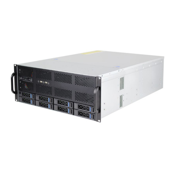
- Page 1 MEC-AI7400SR 4U Edge Server with 4th Gen Intel® Xeon® Processor Scalable Family User’s Manual Manual Rev.: Rev. 0.2 Preliminary Revision Date: May 31, 2024 Part No.: 50M-99307-1000...
-
Page 2: Preface
Preface Copyright © 2024 ADLINK Technology, Inc. This document contains proprietary information protected by copyright. All rights are reserved. No part of this manual may be reproduced by any mechanical, electronic, or other means in any form without prior written permission of the manufacturer. - Page 3 Conventions Information to prevent minor physical injury, component damage, data loss, and/or program corruption when trying to complete a task. Informations destinées à prévenir les blessures corporelles mineures, les dommages aux composants, la perte de données et/ou la corruption mise en garde de programme lors de l'exécution d'une tâche.
-
Page 4: Table Of Contents
Table of Contents ........................4 1 Overview .......................... 5 Introduction ..........................5 Block Diagram ........................6 Mechanical Overview ......................7 1.3.1 MEC-AI7400SR Front Panel ......................7 1.3.2 MEC-AI7400SR Rear Panel ......................8 1.3.3 Mechanical Dimensions ........................9 2 Specifications ........................ 10 MEC-AI7400SR Specifications ..................... -
Page 5: Overview
1 Overview 1.1 Introduction The ADLINK MEC-AI7400SR is a 4U 19" rackmount edge computing server with 4th Gen Intel® Xeon® Processor Scalable Family Processor. The main features of the MEC-AI7400SR include: Single Intel® Sapphire Rapids-SP Family Processor 8x DDR5 DIMMs, 4800MT/s (8 channels, 1DPC) ... -
Page 6: Block Diagram
1.2 Block Diagram Optional... -
Page 7: Mechanical Overview
1.3 Mechanical Overview 1.3.1 MEC-AI7400SR Front Panel USB2.0 SATA1~SATA6... -
Page 8: Mec-Ai7400Sr Rear Panel
1.3.2 MEC-AI7400SR Rear Panel IPMI PCIE Slot 2x10GbE Audi 2xUSB2.0. 2xUSB3.2... -
Page 9: Mechanical Dimensions
1.3.3 Mechanical Dimensions Units: mm... -
Page 10: Specifications
2 Specifications 2.1 MEC-AI7400SR Specifications CPU/Chipset/Memory CPU: Single Intel® Sapphire Rapids Scalable Processor Chipset: Emmitsburg C741 PCH Memory: 8x DDR5 DIMMs, 4800MT/s (8 channels, 1DPC) BIOS AMI BIOS on SPI flash Memory I/O Interface Expansion: 4x FHFL single-slot PCIe Gen.5 x16 slots and 1x FHFL Single-slot PCIe Gen.5 x4 slot OR 4x FHFL dual-slot PCIe Gen.5 x16 slots... - Page 11 LEDS HDD LED NIC1 LED NIC2 LED UID LED Operating System Windows Server 2022 Ubuntu 22.04LTS Mechanical and Environmental Form Factor: 4U 19“ rackmount, 650 x 437.5 x 176.5mm Fans: 3x fans, smart fan speed control Power: 1600W/2000W, AC Plug-in TPM 2.0 module (Optional) Temperature and Humidity Operating: 0°C to 35°C, 5%-95% RH @40°C, non-condensing Storage: -40°C to 70°C, 5%-90% RH, non-condensing...
-
Page 12: Getting Started
3 Getting Started 3.1 Removing the Chassis Cover Follow the instructions below to remove the chassis top cover. All installation procedures are restricted to skilled personnel. Toutes les procédures d'installation sont réservées au personnel qualifié. mise en garde 1. Loosen the three screws around the cover. 2. - Page 13 All installed memory will be automatically detected. No jumpers or settings need to be changed for memory detection. All memory must be of the same type and density. Different memory types can NOT be mixed and matched on the same motherboard.
- Page 14 Recommended Memory Population Table:...
-
Page 15: Pcie Card Installation
3.3 PCIe Card Installation Before installing add-in cards, it’s helpful to know if they are fully compatible with your motherboard. For this reason, we’ve provided the diagrams below, showing the slots that may appear on your motherboard. All installation procedures are restricted to skilled personnel. Only UL listed PCIe expansion cards or PCIe cards with openings less than 5 mm in any dimension are recommended Toutes les procédures d'installation sont réservées au personnel qualifié. -
Page 16: Pcie Slot Secondary Power Supply
3.4 PCIe Slot Secondary Power Supply The MEC-AI7400SR is equipped with six ATX 8pin EPS +12V power connectors on the mainboard to provide secondary power for PCIe expansion cards if required. Two adapter cables are included. The pin definitions of the connectors and cables are described below. -
Page 17: Onboard Lan Led Color Definition
Onboard LAN LED Color Definition Onboard Ethernet ports have green and Amber LEDs to indicate LAN status. The chart below illustrates the different LED states. 3.6 Login in BMC Web The default IP setting is DHCP. Users can modify the IP in BIOS Menu.. If the BMC is connected to a network, after it get an IP address, it will print the IP address on the BIOS booting screen. - Page 18 Default login account: Username: root Password: superuser When logging into the BMC web interface for the first time, you will receive a reminder to change the BMC login password. If you do change it, be sure to make a record of it to avoid being unable to log in later.
-
Page 19: Enter Bios Setup
4 Enter BIOS Setup To enter the BIOS setup screen, follow these steps: 1. Power on the MEC-AI7400SR. 2. Press <F2> or <Del> during POST (<Tab> on remote console) to start the BIOS setup utility. Setup Basics The table below shows how to navigate in the setup program using the keyboard. -
Page 20: Main Menu
4.1 Main Menu In this section, you can alter general features such as the date and time. Note that the options listed below are for options that can directly be changed within the Main Setup screen. BIOS Information It displays BIOS related information. Product Name It displays Product information. - Page 21 Platform Information It displays the processor and PCH information Memory Information Total Memory It displays the total memory size. Memory Frequency It displays Memory frequency System Language Choose the system default language. English / Simplified Chinese / Japanese System Date Set the Date.
-
Page 22: Advanced Menu
4.2 Advanced Menu This section facilitates configuring advanced BIOS options for your system. NOTE: This is a sample screenshot of the Advanced Menu. The HII network drivers displayed here depend on the card(s) you installed and the functions you enabled. Network Stack Configuration Network Stack Settings S5 RTC Wake Settings... - Page 23 Super IO Configuration System Super IO Chip Parameters. Hardware Health Configuration Hardware Health Configuration PCI Subsystem Settings PCI, PCI-X and PCI Express Settings NVMe Configuration NVMe Device information Trusted Computing Trusted Computing settings. CSM Configuration CSM Configuration, Enable/Disable Option ROM execution setting, etc Redfish Host Interface Settings Redfish Host Interface Parameters Tls Auth Configuration...
-
Page 24: Intel ® I210 Gigabit Network Connection
Intel ® I210 Gigabit Network Connection Configure Gigabit Ethernet device parameters. VLAN Configuration (MAC:A0423F4FA133) VLAN Configuration (MAC:A0423F4FA133) MAC: A0423F4FA133-IPv4 Network Configuration Configure IPv4 network parameters.(MAC: A0423F4FA133) MAC: A0423F4FA133-IPv6 Network Configuration Configure IPv6 network parameters.(MAC: A0423F4FA133) - Page 25 Intel® Ethernet Converged Network Adapter X550-T2-A0 Configure 10 Gigabit Ethernet device parameters. VLAN Configuration (MAC:A0423F4FA134) VLAN Configuration MAC:A0423F4FA134 MAC: A0423F4FA134-IPv4 Network Configuration Configure IPv4 network parameters.(MAC: A0423F4FA134) MAC: A0423F4FA134-IPv6 Network Configuration Configure IPv6 network parameters.(MAC: A0423F4FA134) Intel® Ethernet Converged Network Adapter X550-T2-A0 Configure 10 Gigabit Ethernet device parameters.
- Page 26 Network Stack Configuration Network Stack Enable/Disable UEFI Network Stack Disabled / Enabled NOTE: When Network Stack was set to Enabled, the following item will appear. IPv4 PXE Support. Enable/Disable IPv4 PXE boot support. If disabled, IPv4 PXE boot support will not be available. Disabled / Enabled IPv4 HTTPs Support Enable/Disable IPv4 HTTPs boot support.
- Page 27 IPv6 HTTPs Support Enable/Disable IPv6 HTTPs boot support. If disabled, IPv6 HTTPS boot support will not be available. Disabled / Enabled PXE boot wait time Wait time in seconds to press ESC key to abort the PXE boot. Use either +/- or numeric keys to set the value.
-
Page 28: S5 Rtc Wake Settings
S5 RTC Wake Settings Wake system from S5 Enable or disable System wake on alarm event. Select Fixed Time, system will wake on the hr::min::sec specified. Select dynamic Time, system will wake on the current time+ increase minute(s) Disabled / Fixed Time / Dynamic Time... -
Page 29: Serial Port Console Redirection
Serial Port Console Redirection COM1/COM2 Console Redirection Console redirection enable or disable. Disabled / Enabled Legacy Console Redirection Legacy Console Redirection Settings Serial Port for Out-Of-Band Management/Windows Emergency Services (EMS) Console Redirection Console redirection enable or disable. Disabled / Enabled Console Redirection Settings The settings specify how the host computer (which the user is using) will exchange data. -
Page 30: Com1 Console Redirection Settings
COM1 Console Redirection Settings Terminal Type Emulation: ANSI: Extended ASCII char set. VT100: ASCII char set. VT100+: Extends VT100 to support color function keys, etc. VT-UTF8: Uses UTF8 encoding to map Unicode chars onto 1 or more bytes. VT100 / VT100+ / VT-UTF8 / ANSI Bits per Second Select serial port transmission speed. -
Page 31: Flow Control
Stop Bits Stop bits indicate the end of a serial data packet. (A start bit indicates the beginning). The standard setting is 1 stop bit. Communication with slow devices may require more than 1 stop bit. 1 / 2 Flow Control Flow Control can prevent data loss from buffer overflow. - Page 32 COM2 Console Redirection Settings Terminal Type Emulation: ANSI: Extended ASCII char set. VT100: ASCII char set. VT100+: Extends VT100 to support color function keys, etc. VT-UTF8: Uses UTF8 encoding to map Unicode chars onto 1 or more bytes. VT100 / VT100+ / VT-UTF8 / ANSI Bits per Second Select serial port transmission speed.
- Page 33 Stop Bits Stop bits indicate the end of a serial data packet. (A start bit indicates the beginning). The standard setting is 1 stop bit. Communication with slow devices may require more than 1 stop bit. 1 / 2 Flow Control Flow Control can prevent data loss from buffer overflow.
-
Page 34: Legacy Console Redirection Settings
Legacy Console Redirection Settings Redirection COM Port Select a COM port to display redirection of Legacy OS and Legacy OPROM Messages COM1 / COM2 Resolution On Legacy OS, the Number of Rows and Columns supported redirection 80x24 / 80x25 Redirect After POST when Bootloader is selected, then Legacy Console Redirection is disabled before booting to legacy OS, when Always Enable is selected, then Legacy Console Redirection is enabled for Legacy OS. - Page 35 Serial Port for Out-Of-Band Management/Windows Emergency Services (EMS) Console Redirection Settings Out-of Band Mgmt Port Microsoft Windows Emergency Management Services (EMS) allows for remote management of a Windows Server OS through a serial port. COM1 / COM2 Terminal Type VT-UTF8 is the preferred terminal type for out-of-band management. The next best choice is VT100+ and then VT100.
- Page 36 Flow Control Flow Control can prevent data loss from buffer overflow. When sending data, if the receiving buffers are full, a ‘stop’ signal can be sent to stop the data flow. Once the buffers are empty, a ‘start’ signal can be sent to restart the flow.
- Page 37 PCIe Device Configuration Option ROM Dispatch Policy Option ROM Dispatch Policy settings.
- Page 38 Device Class Option ROM Dispatch Policy: LAN1&LAN2 (X550) Enable or Disable X550 LAN1 and LAN2 Option ROM Enabled / Disabled LAN4 (I210) Enable or Disable LAN2 Option Rom Enabled / Disabled PCIE#1 Option ROM Enable or Disable Option ROM execution for selected Slot. Enabled / Disabled PCIE#2 Option ROM...
- Page 39 PCIE#4 Option ROM Enable or Disable Option ROM execution for selected Slot. Enabled / Disabled PCIE#5 Option ROM Enable or Disable Option ROM execution for selected Slot. Enabled / Disabled...
-
Page 40: Xhci Hand-Off
USB Configuration Legacy USB Support Enables legacy USB support. AUTO option disables legacy support if no USB devices are connected. DISABLE option will keep USB devices available only for EFI applications. Enabled / Disabled / Auto XHCI Hand-off This is a workaround for OSes without XHCI hand-off support. The XHCI ownership change should be claimed by XHCI driver. -
Page 41: Usb Transfer Time-Out
USB transfer time-out The time-out value for Control, Bulk and Interrupt transfers. 1 sec / 5 sec / 10 sec / 20 sec Device reset time-out USB mass storage device Start Unit command time-out. 10 sec / 20 sec / 30 sec / 40 sec Device power-up delay Maximum time the device will take before it properly reports itself to the Host Controller. - Page 42 Onboard Device Configuration Onboard VGA Enable/Disable ASPEED VGA Disabled / Enabled LAN1& LAN2 (X550) LAN Enable/Disable control function. Disabled / Enabled LAN4 (I210) LAN4 Enable/Disable control function. Disabled / Enabled Primary Display Select active Video type. Onboard / External NMI Button Enable or disable NMI button.
-
Page 43: Serial Port 2 Configuration
Super IO Configuration Serial Port 1 Configuration Set Parameters of serial Port 1 (COMA) Serial Port 2 Configuration Set Parameters of serial Port 2 (COMB) -
Page 44: Change Settings
Serial Port 1 Configuration Serial Port Select an optimal settings for Super IO Device. Disabled / Enabled NOTE: Serial Port has set to Enabled, the following items will be appear. Change Settings Select an optimal settings for Super IO device. Auto / IO=3F8h;... - Page 45 Serial Port 2 Configuration Serial Port Enable or Disable Serial Port (COM). Disabled / Enabled NOTE: Serial Port has set to Enabled, the following items will be appear. Change Settings Select an optimal settings for Super IO device. Auto / IO=3F8h;...
-
Page 46: Hardware Health Configuration
Hardware Health Configuration Auto Fan Control Auto Fan Control help. Manual / Full Speed PWM Minimal Duty Cycle PWM Minimal Duty Cycle (%). This item is available when Fan Speed Control is set to [Manual]. BMC Alert Beep Enable/Disable BMC Alert Beep. On / Off PMBus support PMBus Support. - Page 47 Sensor Data Register Monitoring When you enter the Sensor Data Register Monitoring submenu, you will see the following dialog window pop out. Please wait 8~10 seconds. NOTE 1: SDR can not be modified. Read only.
-
Page 50: Sr-Iov Support
PCI Device Common Settings Above 4G Decoding Enables or Disables 64bit capable Devices to be decoded in Above 4G Address Space(Only if System supports 64 bit PCI Decoding). Enabled / Disabled SR-IOV Support If system has SR-IOV capable PCIe devices, this option Enables or Disables Single Root IO virtualization Support Enabled / Disabled PCI Express Settings... - Page 51 PCI Express Subsystem Maximum Payload Set Maximum Payload of PCI Express Device or allow System BIOS to select the value. Auto / 128 Bytes / 256 Bytes / 512 Bytes / 1024 Bytes / 2048 Bytes / 4096 Bytes...
-
Page 52: Nvme Configuration
NVMe Configuration... - Page 53 Trusted Computing Security Device Support Enables or disables BIOS support for security device. O.S. will not show Security device. O.S. will not show Security Device. TCG EFI protocol and INT1A interface will not be available. Enabled / Disabled...
- Page 54 CSM Configuration CSM support Enable/Disable CSM Support Enabled / Disabled NOTE:When the CSM support set to Enabled, the following items will appear. Option ROM Messages Set display mode for Option ROM Force BIOS / Keep Current Network Controls the execution of UEFI and legacy PXE OpROM UEFI / legacy Storage Controls the execution of UEFI and legacy PXE OpROM...
- Page 55 Redfish Host Interface Settings Redfish Enable/Disable AMI Redfish. Disabled / Enabled...
- Page 56 Tls Auth Configuration Server CA Configuration Press <Enter> to configure Server CA.
- Page 57 Tls Auth Configuration Enroll Cert Press <Enter> to enroll cert. Delete Cert Press <Enter> to delete cert.
-
Page 58: Discard Changes And Exit
Enroll Cert Configuration Enroll Cert Using File Enroll Cert Using File Cert GUID Input digit character in 11111111-2222-3333-4444-1234567890ab format. Commit Changes and Exit Commit Changes and Exit Discard Changes and Exit Discard Changes and Exit... - Page 59 Delete Cert Configuration FEXXXXXX-XXXX-XXXX-XXXX-XXXXXXXXXX GUID for CERT Disabled / Enabled...
- Page 60 ISCSI Initiator Configuration Host iSCSI Configuration Host iSCSI Configuration settings...
-
Page 61: Iscsi Initiator Name
Host iSCSI Configuration Please follow the instructions to initiate the iSCSI function. Step 1. Select Advanced CSM Configuration Network [UEFI]. Step 2. Select Advanced Network Stack Configuration Network Stack [Enabled] Step 3. Save changes and reboot. iSCSI Initiator Name The worldwide unique name of iSCSI Initiator. - Page 62 Delete Attempts Delete one or more attempts Change Attempt Order Change attempt sequence Add an Attempt Read only.
-
Page 63: Internet Protocol
MAC 36:02:0B:83:D7:63 iSCSI Mode Disabled, Enabled, Enabled for MPIO. Disabled / Enabled / Enabled for MPIO Internet Protocol Initiator IP address is system assigned in IP6 mode. In Autoconfigure mode, iSCSI driver will attempt to connect iSCSI target via IPv4 stack, if failed then attempt IPv6 stack. IPv4 / IPv6 / Autoconfigure Connection Retry Count The minimum value is 0 and the maximum is 16. -
Page 64: Target Address
Configure ISID OUI-format ISID in 6 bytes, default value is derived from MAC address. Only last 3 bytes are configurable. Example: update 0ABBCCDDEEFF to OABBCCF07901 by input F07901. Enable DHCP Enable DHCP. Disabled / Enabled Initiator IP Address Enter IP address in dotted-decimal notation. Initiator Subnet Mask Enter IP address in dotted-decimal notation. - Page 65 MAC A0:42:3F:37:EA:08 iSCSI Mode Disabled, Enabled, Enabled for MPIO. Disabled / Enabled / Enabled for MPIO Internet Protocol Initiator IP address is system assigned in IP6 mode. In Autoconfigure mode, iSCSI driver will attempt to connect iSCSI target via IPv4 stack, if failed then attempt IPv6 stack. IPv4 / IPv6 / Autoconfigure Connection Retry Count The minimum value is 0 and the maximum is 16.
- Page 66 Configure ISID OUI-format ISID in 6 bytes, default value is derived from MAC address. Only last 3 bytes are configurable. Example: update 0ABBCCDDEEFF to OABBCCF07901 by input F07901. Enable DHCP Enable DHCP. Disabled / Enabled Initiator IP Address Enter IP address in dotted-decimal notation. Initiator Subnet Mask Enter IP address in dotted-decimal notation.
- Page 67 Delete Attempts Attempt 1 MAC: A0:42:3F:37:EA:08, PFA: Bus 97/ Dev 0 / Func 0, iSCSI mode: Enabled, IP version: IPv4. Disabled / Enabled Attempt 2 MAC: 36:02:0B:83:D7:63, PFA: Bus 35 / Dev 0 / Func 3, iSCSI mode: Disabled, IP version: IPv4. Disabled / Enabled Attempt 3 MAC: 36:02:0B:83:D7:63, PFA: Bus 35 / Dev 0 / Func 3, iSCSI mode: Disabled, IP version: IPv4.
- Page 68 Change Attempt Order Change Attempt Order Change the order of Attempts using +/- keys. Use arrow keys to select the attempt then press +/- to move the attempt up/down in the attempt order list. Attempt 1 / Attempt 2 / Attempt 3 Commit Changes and Exit Commit Changes and Exit.
- Page 69 VLAN Configuration Enter Configuration Press ENTER to enter configuration menu for VLAN configuration.
-
Page 70: Enter Configuration
Enter Configuration VLAN ID VLAN ID of new VLAN or existing VLAN, valid value is 0~4094 Priority 802.1Q Priority, valid value is 0~7 Add VLAN Create a new VLAN or update existing VLAN Remove VLAN Remove selected VLANs... -
Page 71: Local Ip Address
MAC: 4E722FER47F30-IPv4 Network Menu Configured Indicate whether network address configured successfully or not. Disabled / Enabled NOTE: When Configured was set to Enabled, the following items will be available to set up. Enable DHCP Indicate whether network address configured successfully or not. Disabled / Enabled Local IP Address Enter IP address in dotted-decimal notation. - Page 72 Save Changes and Exit Save Changes and Exit MAC: 4E722FER47F30-IPv6 Network Menu Enter Configuration Menu Press ENTER to enter configuration menu for IPv6 configuration.
-
Page 73: Save Changes And Exit
Enter Configuration Menu Interface ID The 64 bit alternative interface ID for the device. The string is colon separated. e.g. ff:dd:88:66:cc:1:2:3 DAD Transmit Count The number of consecutive Neighbor Solicitation message sent while performing Duplicate Address Detection on a tentative address. A value of zero indicates that duplicate address detection is not performed. -
Page 74: Nic Configuration
Intel® I210 Gigabit Network Connection Settings Firmware Image Properties View device firmware version information. NIC Configuration Click to configure the network device port. Blink LEDs Blink LEDs for a duration up to 15 seconds. - Page 75 Firmware Image Properties Settings Only Read...
-
Page 76: Link Speed
NIC Configuration Settings Link Speed Specifies the port speed used for the selected boot protocol Auto Negotiated / 10 Mbps Half / 10 Mbps Full / 100 Mbps Half / 100 Mbps Full Wake on LAN Enables power on of the system via LAN. Note that configuring Wake on LAN in the operating system does not change the value of this setting, but does override the behavior of Wake on LAN in OS controlled power states. - Page 77 VLAN Configuration (MAC: A0423F4FA133) Enter Configuration Menu Press ENTER to enter configuration menu for VLAN configuration.
- Page 78 Enter Configuration Settings VLAN ID VLAN ID of new VLAN or existing VLAN, valid value is 0~4094 Priority 802.1Q Priority, valid value is 0~7 Add VLAN Create a new VLAN or update existing VLAN Remove VLAN Remove selected VLANs...
- Page 79 MAC: A0423F4FA133-IPv4 Network Menu Configured Indicated whether network address configured successfully. Save Changes and Exit Save changes and exit.
- Page 80 MAC: A0423F4FA133-IPv6 Network Menu Enter Configuration Menu Press ENTER to enter configuration menu for IPv6 configuration.
- Page 81 Enter Configuration Menu Interface ID The 64 bit alternative interface ID for the device. The string is colon separated. E.g. ff:dd:88:66::cc:1:2:3 DAD Transmit Count The number of consecutive Neighbor Solicitation message sent while performing duplicate address detection on a tentative address. A value of zero indicates that duplicate address detection is not performed.
- Page 82 Intel® Ethernet Converged Network Adapter X550-T2-A0 Firmware Image Properties View device firmware version information. NIC Configuration Clink to configure the network device port. Blink LEDs Blink LEDs for a duration up to 15 seconds.
- Page 83 Firmware Image Properties Only Read...
- Page 84 NIC Configuration Wake on LAN Enables power on of the system via LAN. Note that configuring Wake on LAN in the operating system does not change the value of this setting, but does override the behavior of Wake on LAN in OS controlled power states.
- Page 85 VLAN Configuration (MAC: A0423F4FA134) Enter Configuration Menu Press Enter to enter configuration menu for VLAN configuration...
- Page 86 Enter Configuration Menu VLAN ID VLAN ID of new VLAN or existing VLAN, valid value is 0~4094 Priority 802.1Q Priority, valid value is 0~7 Add VLAN Create a new VLAN or update existing VLAN Remove VLAN Remove selected VLANs...
- Page 87 MAC: A0423F4FA134-IPv4 Network Menu Configured Indicate whether network address configured sucessfully or not. Enabled / Disabled Save Changes and Exit Save Changes and exit...
- Page 88 MAC: A0423F4FA134-IPv6 Network Menu Enter Configuration Menu Press ENTER to enter configuration menu for IPv6 configuration.
- Page 89 Enter Configuration Menu Interface ID The 64 bit alternative interface ID for the device. The string is colon separated. E.g. ff:dd:88:66::cc:1:2:3 DAD Transmit Count The number of consecutive Neighbor Solicitation message sent while performing duplicate address detection on a tentative address. A value of zero indicates that duplicate address detection is not performed.
- Page 90 Intel® Ethernet Converged Network Adapter X550-T2-A0 Firmware Image Properties View device firmware version information. NIC Configuration Clink to configure the network device port. Blink LEDs Blink LEDs for a duration up to 15 seconds.
- Page 91 Firmware Image Properties Only Read...
- Page 92 NIC Configuration Wake on LAN Enables power on of the system via LAN. Note that configuring Wake on LAN in the operating system does not change the value of this setting, but does override the behavior of Wake on LAN in OS controlled power states.
- Page 93 VLAN Configuration (MAC: A0423F4FA135) Enter Configuration Menu Press Enter to enter configuration menu for VLAN configuration...
- Page 94 Enter Configuration Menu VLAN ID VLAN ID of new VLAN or existing VLAN, valid value is 0~4094 Priority 802.1Q Priority, valid value is 0~7 Add VLAN Create a new VLAN or update existing VLAN Remove VLAN Remove selected VLANs...
- Page 95 MAC: A0423F4FA135-IPv4 Network Menu Configured Indicate whether network address configured sucessfully or not. Enabled / Disabled Save Changes and Exit Save Changes and exit...
- Page 96 MAC: A0423F4FA134-IPv6 Network Menu Enter Configuration Menu Press ENTER to enter configuration menu for IPv6 configuration.
- Page 97 Enter Configuration Menu Interface ID The 64 bit alternative interface ID for the device. The string is colon separated. E.g. ff:dd:88:66::cc:1:2:3 DAD Transmit Count The number of consecutive Neighbor Solicitation message sent while performing duplicate address detection on a tentative address. A value of zero indicates that duplicate address detection is not performed.
-
Page 98: Cpu Configuration Subsystem
4.3 CPU Configuration Subsystem Processor Configuration Displays and provides option to change the Processor Settings. Common RefCode Configuration Displays and provides option to change the Common RefCode Settings. Uncore Configuration Displays and provides option to change the Uncore Settings Memory Configuration Displays and provides option to change the Memory Settings. -
Page 99: Hardware Prefetcher
Processor Configuration Enabled LP [Global] Enabled sd Logical processor (software method to Enabled/Disabled logical processor threads) (Hyper-Threading). ALL LPs / Single LP Enable Intel® TXT Enable Intel® TXT. Disabled / Enabled Hardware Prefetcher =MLC Streamer Prefetcher (MSR 1A4h Bit [0]). Disabled / Enabled Adjacent Cache Prefetch =MLC Spatial Prefetcher (MSR 1A4h Bit [1]). -
Page 100: Common Refcode Configuration
Extended APIC Enabled/Disabled extended APIC support Note: This will Enabled VT-d automatically if x2APIC is Enabled. Disabled / Enabled AES-NI Enabled/Disabled AES-NI support. Disabled / Enabled Common RefCode Configuration Numa Enabled or Disabled Non uniform Memory Access(NUMA). Disabled / Enabled... - Page 101 Uncore Configuration Uncore General Configuration Displays and provides option to change the uncore General settings.
- Page 102 Uncore General Configuration Uncore Status Uncore Status Help Link Speed Mode Select the UPI link speed as either the POR speed (fast) default speed (slow) Slow / Fast Link Frequency Select Allows for selecting the UPI Link frequency 12.8GT/s / 14.4 GT/s / 16.0 GT/s / Auto / Use Per Link Setting Link L0p Enabled Enabled –...
- Page 103 Disabled supports 1-cluster and 4-IMC way interleave. Enabled SNC2 supports 2- clusters SNC and 2- way IMC interleave. Enabled SNC4 supports 4-cluster and 1- IMC way interleave. Disabled / Enabled SNC2 (2-clusters) / Enabled SNC4 (4-clusters) MMCFG Base Select MMCFG Base, Auto –...
- Page 104 Uncore General Configuration...
-
Page 105: Memory Topology
Memory Configuration Memory Frequency Maximum Memory Frequency Selections in MT/s. If Enforce POR is disabled, user will be able to run at higher frequencies than the memory support (limited by processor support). Do not select Reserved. Auto / 4000 / 4400 / 4800 Memory Topology Displays memory topology with Dimm population information Memory RAS Configuration... - Page 106 Memory Topology...
-
Page 107: Mirror Mode
Memory RAS Configuration Dynamic ECC Mode Selection Enabled/Disabled Dynamic ECC Mode selection Disabled / Enabled Mirror Mode Full Mirror mode will set entire 1LM memory in system to be mirrored , consequently reducing the memory capacity by half. Partial Mirror Mode will enable the required size of memory to be mirrored. If rank sparing is enabled partial mirroring will not take effect. -
Page 108: Patrol Scrub
Patrol Scrub Enabled/Disabled Patrol Scrub Disabled / Enabled Patrol Scrub Interval Enabled/Disabled Patrol Scrub Disabled / Enabled Patrol Scrub Interval Select the number of hours (1-24) required to complete full scrub. A value of zero means auto! -
Page 109: Intel® Vt For Directed I/O (Vt-D)
IIO Configuration Socket0 Configuration Press <Enter> to bring up the Socket0 Configuration Intel® VT for Directed I/O (VT-d) Press <Enter> to bring up the Intel® VT for Directed I/O (VT-d) Configuration menu. Intel® VMD Technology Press <Enter> to bring up the Intel® VMD for Volume Management Device Configuration menu. PCIe Hot Plug Enabled/Disabled PCIe Hot Plug globally. - Page 110 PCIe Max Read Request Size This option can set requested Max Read Request Size in PCI Hierarchy.’Default’ keeps hardware default. Auto / 128B / 256B / 512B / 1024B / 2048B / 4096B...
-
Page 111: Socket0 Configuration
Socket0 Configuration IOU0 (IIO PCIe Port 1) Selects PCIe port Bifurcation for selected slot(s) Port Format:xDxCxBxA. The port can further be x2x2 Auto / x4x4x4x4 / x4x4_x8 / x_x8x4x4 / x_x8x_x8 / x_x_x_x16 IOU1 (IIO PCIe Port 2) Selects PCIe port Bifurcation for selected slot(s) Port Format: xDxCxBxA. The port can further be x2x2 Auto / x4x4x4x4 / x4x4_x8 / x_x8x4x4 / x_x8x_x8 / x_x_x_x16 IOU2 (IIO PCIe Port 3) - Page 112 IOU3 (IIO PCIe Port 4) Selects PCIe port Bifurcation for selected slot(s) Port Format: xDxCxBxA. The port can further be x2x2 Auto / x4x4x4x4 / x4x4_x8 / x_x8x4x4 / x_x8x_x8 / x_x_x_x16 IOU4 (IIO PCIe Port 5) Selects PCIe port Bifurcation for selected slot(s). Auto / x4x4x4x4 / x4x4_x8 / x_x8x4x4 / x_x8x_x8 / x_x_x_x16 Port 1A/2A/3A/4A/5A/5C/5E/5G Settings related to PCI Express Ports...
- Page 113 PCI-E Port In auto mode the BIOS will remove the EXP port if there is no device or errors on that device and the device is not HP capable. Enabled/Disabled is used to enable/disable the port and expose/hide its CFG space.
- Page 114 Intel® VT for Directed I/O (VT-d) Intel® VT for Directed I/O Enable/Disable Intel® Virtualization Technology for Directed I/O (VT-d) by reporting the I/O device assignment to VMM through DMAR ACPI Tables. Enabled / Disabled Pre-boot DMA Protection Enable DMA Protection in Pre-boot environment (If DMAR table is installed in DXE and If VTD_INFO_PPI is installed in PEI.) Enabled / Disabled PCIe ACSCTL...
- Page 115 Intel® VMD Technology...
- Page 116 Intel VMD for Volume Management for Socket 0 VMD Config for IOU0 Enable/Disable VMD in this Stack. Disabled / Enabled VMD Config for IOU1 Enable/Disable VMD in this Stack. Disabled / Enabled VMD Config for IOU2 Enable/Disable VMD in this Stack. Disabled / Enabled VMD Config for IOU3...
- Page 117 Advanced Power Management Configuration CPU P State Control P State Control Configuration Sub Menu, include Turbo, XE and ete. Hardware PM State Control Hardware P-State setting CPU C State Control CPU C State setting. Package C State Control Package C State setting CPU Advanced PM Tuning Setting Energy Per Bias, Pwr_Ctl, PP0 Current SWLTD, SAPM etc Package Current Config...
-
Page 118: Turbo Mode
CPU P State Control Configuration SpeedStep (Pstates) Enable/Disable EIST (P-States). Disabled / Enabled Boot performance mode Select the performance state that the BIOS will set before OS hand off. Max Performance / Max Efficient / Set by Intel Node Manager Energy Efficient Turbo Energy Efficient Turbo Disable, MSR 0x1FC [19]. - Page 119 Hardware PM State Control Hardware P-States Disabled: Hardware choose a P-state based on OS Request (Legacy P-States) Native Mode: Hardware choose a P-state based on OS guidance Out of Band Mode: Hardware autonomously chooses a P-state (no OS guidance) Disabled / Native Mode / Out of Band Mode / Native Mode with No Legacy Support...
-
Page 120: Enhanced Halt State (C1E)
CPU C State Control CPU C1 auto demotion Allows CPU to automatically demote to C1. Takes effect after reboot. Disabled / Enabled CPU C6 report Enable/Disable CPU C6 (ACPI C3) report to OS. Disabled / Enabled / Auto Enhanced Halt State (C1E) Core C1E auto promotion Control. - Page 121 Package C State Control Package C State Package C State limit C0/C1 state / C2 state / C6(non Retention) state / C6(Retention) state / No Limit / Auto...
- Page 122 CPU Advanced PM Tuning Power Performance Tuning Options decide who Controls EPB. In OS mode: IA32_ENERGY_PERF_BIAS is used In BIOS mode: ENERGY_PERF_BIAS_CONFIG is used In PECI mode: PCS53 is used OS Controls EPB / BIOS Controls EPB / PECI Controls EPB...
- Page 123 Package Current Config Current Limit Override Disable – Default, do nothing; Enable, override Current limitation in 1/8 A increments. Disabled / Enabled...
- Page 124 SOCKET RAPL Configuration PL1 Power Limit PL1 Power Limit in Watts. The value may vary from 0 to Fused Value. If the value is 0, the fused value will be programmed. A value greater than fused TDP value will not be programmed. PL1 Time Window PL1 value in seconds.
-
Page 125: Chipset Menu
4.4 Chipset Menu PCH-IO Configuration PCH Parameters Server ME Configuration Configure Server ME Technology Parameters... -
Page 126: Sata And Rst Configuration
PCH-IO Configuration PCI Express Configuration PCI Express Configuration settings SATA And RST Configuration Device Options Settings Deep Sx Configuration Deep Sx Option Settings Restore AC Power Loss Specify what state to go to when power is re-applied after a power failure (G3 state). Power On / Power Off / Last State... - Page 127 PCI Express Configuration PCI Express Root Port 1~16...
- Page 128 PCI Express Root Configuration1~16 PCI Express Root Port 1 Control the PCI Express Root Port. Disabled / Enabled ASPM PCI Express Active State Power Management Settings. Disabled / L1 L1 Substates PCI Express L1 Substates settings. Disabled / L1.1 / L1.2 / L1.1 & L1.2 PCIe Speed Configure PCIe Speed Auto / Gen1 / Gen2 / Gen3...
- Page 129 SATA And RST Configuration Controller 0 SATA And RST Configuration SATA Controller 0 Device Options Settings Controller 1 SATA And RST Configuration SATA Controller 1 Device Options Settings...
-
Page 130: Sata Controller(S)
Controller 0 SATA And RST Configuration SATA Controller(S) Enabled/Disabled SATA Device. Enabled / Disabled SATA Mode Selection Determines how SATA controllers operate. AHCI / RAID Port 4 Enabled or Disabled SATA Port Enabled / Disabled Hot Plug Designates this port as Hot Pluggable. Enabled / Disabled Spin Up Device If enabled for any of ports Staggerred Spin Up will be performed and only the drives which have this option... - Page 131 SATA Device Type Indentify the SATA port is connected to Solid State Drive or Hard Disk Drive Hard Disk Drive / Solid State Drive Controller 1 SATA And RST Configuration SATA Controller(s) Enabled/Disabled SATA Device. Enabled / Disabled SATA Mode Selection Determines how SATA controllers operate.
- Page 132 Hot Plug Designates this port as Hot Pluggable. Enabled / Disabled Spin Up Device If enabled for any of ports Staggered Spin Up will be performed and only the drives which have this option enabled will spin up at boot. Otherwise all drives spin up at boot. Enabled / Disabled SATA Device Type Indentify the SATA port is connected to Solid State Drive or Hard Disk Drive.
- Page 133 Spin Up Device If enabled for any of ports Staggered Spin Up will be performed and only the drives which have this option enabled will spin up at boot. Otherwise all drives spin up at boot. Enabled / Disable SATA Device Type Identify the SATA port is connected to Solid State Drive or Hard Disk Drive.
- Page 134 SATA1 Port 7 Port 7 Enable or Disabled SATA Port Enabled / Disabled Hot Plug Designates this port as Hot Pluggable. Enabled / Disabled Spin Up Device If enabled for any of ports Staggered Spin Up will be performed and only the drives which have this option enabled will spin up at boot.
-
Page 135: Server Me Configuration
Platform Deep S5 Mode Enabled – Enabled Platform Deep S5 mode, Disable – Disable Platform Deep S5 mode, Hardware– No support Platform Deep S5 mode Disabled / Enabled / Hardware Platform Deep S5 Delay Time Delay (0/3/6/10) seconds to enter deep S5 state 0S/3S/6S/10S Server ME Configuration Only Read... -
Page 136: Server Management
4.5 Server Management FRB-2 Timer Enable or Disable FRB-2 timer (POST timer). Enabled / Disabled NOTE: When FRB-2 Timer was set to Enabled, the following 3 items will be available. FRB-2 Timer timeout Enter value Between 3 to 6 min for FRB-2 Timer Expiration value. 3 minutes / 4 minutes / 5 minutes / 6 minutes / 12 minutes FRB-2 Timer Policy Configure how the system should respond if the FRB-2 Timer expires. -
Page 137: System Event Log
OS Wtd Timer timeout Configure the length of the OS Boot Watchdog Timer. Not available if OS Boot Watchdog timer is disabled. 5 minutes / 10 minutes / 15 minutes / 20 minutes OS Wtd Timer Policy Configure how the system should respond if the OS Boot Watchdog Timer expires. Not available if OS Boot Watchdog timer is disabled. -
Page 138: Erase Sel
System Event Log Configuration SEL Components Change this to enable or disable event logging for error/progress codes during boot. Disabled / Enabled Erase SEL Choose options for erasing SEL. No / Yes, On next reset / Yes, On every reset Log EFI Status Codes Disable the logging of EFI Status Codes or log only error code or only progress code or both. -
Page 139: Management Port
BMC Network Configuration Configure IPV4 Support Management Port 1 Configuration Address Source Select the configure LAN channel parameters statically or dynamically (by BIOS or BMC). Unspecified option will not modify any BMC network parameters during BIOS phase. Unspecified / Static / DynamicBmcDhcp / DynamicBmcNonDhcp Management Port 2 Enable/Disable BMC Share Nic. -
Page 140: Configuration Address Source
Configuration Address Source Select the configure LAN channel parameters statically or dynamically (by BIOS or BMC). Unspecified option will not modify any BMC network parameters during BIOS phase. Unspecified / Static / DynamicBmcDhcp Server Management Port 2 IPV6 Support Enable or Disable LAN1 IPV6 Support. Enabled / Disabled IPv6 Support Enable or Disable LAN2 IPv6 Support. -
Page 141: Delete User
BMC User Setting Configuration Add User Press< Enter> to Add a User Delete User Press<Enter> to Delete a User Change User Settings Press<Enter> to Change User settings... - Page 142 BMC Add User Configuration User Name Enter BMC User Name...
- Page 143 BMC Delete User Configuration User Name Enter BMC User Name...
- Page 144 BMC Change User Configuration User Name Enter BMC User Name...
-
Page 145: Security
4.6 Security Password Description Read only. Administrator Password Set administrator password in the Create New Password window. After you key in the password, the Confirm New Password window will pop out to ask for confirmation. User Password Set user password in the Create New Password window. After you key in the password, the Confirm New Password window will pop out to ask for confirmation. -
Page 146: Secure Boot Mode
Secure Boot Secure Boot Secure boot feature is Active if Secure Boot is Enabled, Platform Key (PK) is enrolled and System is in User mode. The mode change requires platform reset. Disabled / Enabled Secure Boot Mode Secure Boot mode selector: Standard/Custom. In Custom mode Secure Boot Variables can be configured without authentication. - Page 147 Key Management Factory keys Provision Allow to provision factory default Secure Boot keys when System is in Setup Mode. Disabled / Enabled Restore Factory Keys Force System to User Mode. Install Factory Default Secure Boot key databases. Reset To Setup Mode Delete all Secure Boot key database from NVRAM Enroll Efi Image Allow the image to run in Secure Boot mode.
- Page 148 Platform Key (PK) Enroll Factory Defaults or load certificates from a file: 1. Public Key Certificate: a) EFI_SIGNATURE_LIST b) EFI_CERT_X509 (DER) c) EFI_CERT_RSA2048 (bin) d) EFI_CERT_SHAXXX 2. Authenticated UEFI Variable 3. EFI PE/C0FF Image (SHA256) Key source: Default, External, Mixed Update Key Exchange Keys Enroll Factory Defaults or load certificates from a file:...
- Page 149 Authorized TimeStamps Enroll Factory Defaults or load certificates from a file: 1. Public Key Certificate: a) EFI_SIGNATURE_LIST b) EFI_CERT_X509 (DER) c) EFI_CERT_RSA2048 (bin) d) EFI_CERT_SHAXXX 2. Authenticated UEFI Variable 3. EFI PE/C0FF Image (SHA256) Key source: Factory, External, Mixed Update / Append OsRecovery Signatures Enroll Factory Defaults or load certificates from a file: 1.
-
Page 150: Boot
4.7 Boot Setup Prompt Timeout Number of seconds to wait for setup activation key. 65535 (0xFFFF) means indefinite waiting. Bootup NumLock State Select the keyboard NumLock state. Off / On Quiet Boot Enable or disable Quiet Boot option. Disabled / Enabled Wait for ‘ESC’... -
Page 151: Delete Boot Option
Boot Option Priorities Boot Option #1~#6 Select the first/second boot device. Device Name / Disabled Add New Boot Option Add a new EFI boot option to the boot order Delete Boot Option Remove an EFI boot option from the boot order Add New Boot Management Add boot option Create new boot option... - Page 152 Delete Boot Option Delete Boot Option Remove an EFI boot option from the boot order Select one to Delete / Device Name...
-
Page 153: Save & Exit
4.8 Save & Exit Save Changes and Exit Exit system setup after saving the changes. Discard Changes and Exit Exit system setup without saving any changes. Save Changes and Reset Reset the system after saving the changes. Discard Changes and Reset Reset system setup without saving any changes. -
Page 154: Restore User Defaults
Save as User Defaults Save the changes done so far as User Defaults. Restore User Defaults Restore the User Defaults to all the setup options. Boot Override Read only. -
Page 155: Diagnostics
5 Diagnostics 5.1 AMIBIOS Post Code (Aptio) The POST code checkpoints are the largest set of checkpoints during the BIOS pre- boot process. The following table describes the type of checkpoints that may occur during the POST portion of the BIOS: Checkpoint Ranges Status Code Range Description... - Page 156 SEC Error Codes 0x0C – 0x0D Reserved for future AMI SEC error codes 0x0E Microcode not found 0x0F Microcode not found SEC Beep Codes None PEI Phase Status Code Description Progress Codes 0x10 PEI Core is started 0x11 Pre-memory CPU initialization is started 0x12 Pre-memory CPU initialization (CPU module specific) 0x13...
- Page 157 Status Code Description 0x38 Post-Memory North Bridge initialization (North Bridge module specific) 0x39 Post-Memory North Bridge initialization (North Bridge module specific) 0x3A Post-Memory North Bridge initialization (North Bridge module specific) 0x3B Post-Memory South Bridge initialization is started 0x3C Post-Memory South Bridge initialization (South Bridge module specific) 0x3D Post-Memory South Bridge initialization (South Bridge module specific) 0x3E...
- Page 158 Recovery Progress Codes 0xF0 Recovery condition triggered by firmware (Auto recovery) 0xF1 Recovery condition triggered by user (Forced recovery) 0xF2 Recovery process started 0xF3 Recovery firmware image is found 0xF4 Recovery firmware image is loaded 0xF5 – 0xF7 Reserved for future AMI progress codes Recovery Error Codes 0xF8 Recovery PPI is not available...
- Page 159 Status Code Description 0x76 South Bridge DXE initialization (South Bridge module specific) 0x77 South Bridge DXE initialization (South Bridge module specific) 0x78 ACPI module initialization 0x79 CSM initialization 0x7A – 0x7F Reserved for future AMI DXE codes 0x80 – 0x8F OEM DXE initialization codes 0x90 Boot Device Selection (BDS) phase is started...
- Page 160 Status Code Description 0xAF Exit Boot Services event 0xB0 Runtime Set Virtual Address MAP Begin 0xB1 Runtime Set Virtual Address MAP End 0xB2 Legacy Option ROM initialization 0xB3 System Reset 0xB4 USB hot plug 0xB5 PCI bus hot plug 0xB6 Clean-up of NVRAM 0xB7 Configuration Reset (reset of NVRAM settings)
- Page 161 Status Code Description 0x40 System is waking up from the S4 sleep state 0xAC System has transitioned into ACPI mode. Interrupt controller is in PIC mode. 0xAA System has transitioned into ACPI mode. Interrupt controller is in APIC mode.
- Page 162 MEC-AI7400SR This page intentionally left blank...
-
Page 163: Important Safety Instructions
MEC-AI7400SR Important Safety Instructions For user safety, please read and follow all instructions, WARNINGS, CAUTIONS, and NOTES marked in this manual and on the associated equipment before handling/operating the equipment. 1. Read these safety instructions carefully. 2. Keep this user’s manual for future reference. - Page 164 MEC-AI7400SR 9. This equipment is not suitable for use in locations where children are likely to be present. 10. Equipment must be serviced by authorized technicians when: The power cord or plug is damaged; • Liquid has penetrated the equipment;...
-
Page 165: Consignes De Sécurité Importantes
MEC-AI7400SR Consignes de Sécurité Importantes Pour assurer la sécurité de l’utilisateur, veuillez lire et suivre toutes les directives, ainsi que les AVERTISSEMENTS, MISES EN GARDE et REMARQUES de ce manuel et indiqués sur l’équipement associé avant de manipuler ou utiliser l’équipement. - Page 166 MEC-AI7400SR Risque d'explosion si la batterie est remplacée par une batterie d'un type incorrect. Jetez les piles usagées conformément aux instructions du fabricant. mise en garde 9. Cet équipement ne convient pas à une utilisation dans des lieux pouvant accueillir des enfants.
-
Page 167: Getting Service
6450 Via Del Oro, San Jose, CA 95119-1208, USA Tel: +1-408-360-0200 Toll Free: +1-800-966-5200 (USA only) Fax: +1-408-600-1189 Email: info@adlinktech.com ADLINK Technology (China) Co., Ltd. Address: 上海市浦东新区张江高科技园区芳春路 300 号 (201203) 300 Fang Chun Rd., Zhangjiang Hi-Tech Park, Pudong New Area Shanghai, 201203 China Tel: +86-21-5132-8988 Fax: +86-21-5132-3588 Email: market@adlinktech.com...
Need help?
Do you have a question about the MEC-AI7400SR and is the answer not in the manual?
Questions and answers