Sign In
Upload
Manuals
Brands
ADLINK Technology Manuals
Computer Hardware
RQI-53
ADLINK Technology RQI-53 Manuals
Manuals and User Guides for ADLINK Technology RQI-53. We have
1
ADLINK Technology RQI-53 manual available for free PDF download: User Manual
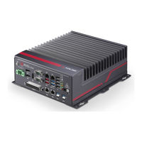
ADLINK Technology RQI-53 User Manual (95 pages)
Embedded Real-Time Robotic Controller with Intel Xeon/Core Processor
Brand:
ADLINK Technology
| Category:
Computer Hardware
| Size: 4.11 MB
Table of Contents
Preface
3
Table of Contents
5
List of Tables
7
List of Figures
9
Introduction
11
Overview
11
Features
11
Packing List
11
Optional Accessories
12
Specifications
13
Rqi-58(-E), Rqi-57(-E)
13
Rqi-55(-E), Rqi-53(-E)
16
Roscube-I Series Functional Block Diagram
19
Figure 2-1: Roscube-I Series Functional Block Diagram
19
Display Options
20
Table 2-1: Maximum Display Resolution Configurations
20
Mechanical Dimensions
21
Figure 2-2: Roscube-I Series Top View
21
Figure 2-3: Roscube-I Series Side View
22
Figure 2-4: Roscube-I Series Front View
23
System Layout
25
Front Panel
25
Table 3-1: Front Panel I/O Legend
25
Figure 3-1: Front Panel I/O
25
Table 3-2: Front Panel I/O - Expansion Box Legend
26
Figure 3-2: Front Panel I/O - Expansion Box
26
Table 3-3: Displayport Pin Definition
28
Table 3-4: Applicable Cable Types
28
Table 3-5: Multi-I/O DB-50 Connector Pin Definition
29
Figure 3-3: Digital Input Circuit
30
Figure 3-4: Digital Output Circuit
30
Table 3-6: Canbus Module Support Table
31
Table 3-7: DI/DIO Parameter Table
31
Table 3-8: HDMI Connector Pin Definition
32
Table 3-9: Ethernet Port Pin Definition
34
Table 3-10: Active/Link LED Indicators
34
Table 3-11: Speed LED Indicators
34
Figure 3-5: Ethernet Port and Leds
34
Table 3-12: DC Power Input Pin Definition
35
Figure 3-6: DC Power Input
35
Table 3-13: COM Port D-Sub 9-Pin Signal Functions
36
Figure 3-7: COM Port Pin Definition
36
Internal I/O Connectors
37
Figure 3-8: Board Layout
37
Table 3-14: Mainboard Connector Legend
38
Figure 3-9: Mainboard Connectors
38
Table 3-15: Function Module Connector Legend
39
Figure 3-10: Function Module Connectors
39
Table 3-16: GPS Module Power Header Pin Definition
40
Figure 3-11: GPS Module Power Header Pin Definition
40
Figure 3-12: Clear CMOS Jumper Setting
40
Table 3-17: Power/Reset Header Pin Definition
41
Table 3-18: Canbus Wafer Connector Pin Definition
41
Figure 3-13: PWR/RESET Header Pin Definition
41
Getting Started
43
Attaching the DC Power Connector
43
Mounting the Roscube-I Series
44
A Appendix: Power
47
Power Consumption Reference
47
Table A-1: Power Consumption
47
B Appendix: BIOS Setup
49
Main
50
Advanced
51
Chipset
66
Security
75
Boot
77
Save & Exit
79
C Appendix: Watchdog Timer
81
WDT with Linux
81
D Appendix: I/O Operation
83
DI/O
83
Leds
87
Serial Ports
88
Important Safety Instructions
89
Consignes de Sécurité Importante
91
Getting Service
95
Advertisement
Advertisement
Related Products
ADLINK Technology ROScube Pico BSP
ADLINK Technology ROScube-I Series
ADLINK Technology RQI-58
ADLINK Technology RQI-57
ADLINK Technology RQI-55
ADLINK Technology RQI-58-E
ADLINK Technology RQI-57-E
ADLINK Technology RQI-55-E
ADLINK Technology RQI-53-E
ADLINK Technology ROScube-Pico TGL RQP-T35
ADLINK Technology Categories
Computer Hardware
Motherboard
PCI Card
Control Unit
I/O Systems
More ADLINK Technology Manuals
Login
Sign In
OR
Sign in with Facebook
Sign in with Google
Upload manual
Upload from disk
Upload from URL