
Related Manuals for ADLINK Technology NuPRO-A331


Summary of Contents for ADLINK Technology NuPRO-A331
- Page 1 NuPRO-A331 Full-Size PICMG 1.0 Intel® Core™ i7/i5/i3 Q57 Express Chipset SBC User’s Manual Manual Rev.: 2.02 Revision Date: May 27, 2016 Part No: 50-13067-1020 Advance Technologies; Automate the World.
- Page 2 Revision History Revision Release Date Description of Change(s) 2.00 2010/12/31 Initial release Correct PICMG “1.3” to “1.0”, update DVI cable 2.01 2011/02/17 P/N, remove SATA power cable from packing list 2.02 2016/5/27 I/O spec listing adjusted...
- Page 3 NuPRO-A331 Preface Copyright 2016 ADLINK Technology Inc. This document contains proprietary information protected by copy- right. All rights are reserved. No part of this manual may be repro- duced by any mechanical, electronic, or other means in any form without prior written permission of the manufacturer.
- Page 4 NuPRO-A331. Chapter 3, Getting Started: Illustrates how to install components on the NuPRO-A331 such as CPU, heatsink, and memory mod- ules. Chapter 4, Driver Installation: Provides information on how to install the NuPRO-A331 device drivers.
- Page 5 NuPRO-A331 Conventions Take note of the following conventions used throughout this manual to make sure that users perform certain tasks and instructions properly. Additional information, aids, and tips that help users perform tasks. NOTE: NOTE: Information to prevent minor physical injury, component dam- age, data loss, and/or program corruption when trying to com- plete a task.
- Page 6 This page intentionally left blank. Preface...
-
Page 7: Table Of Contents
NuPRO-A331 Table of Contents NuPRO-A331................i Revision History..............ii Preface ..................iii Table of Contents..............vii List of Figures ................ xi List of Tables................ xiii 1 Introduction ................ 1 Overview................1 Features................2 Specifications............... 3 Block Diagram ..............5 Functional Description ............6 Mechanical Drawing ............ - Page 8 Installing Memory Modules ..........34 Installing the Power Connectors ........36 4 Driver Installation.............. 37 Intel® Rapid Storage Technology Driver ......37 Intel® Q57 Express Chipset Driver ........38 Display Driver..............38 Ethernet Driver..............39 Intel® Rapid Storage Technology Utility ......39 TPM Driver.................
-
Page 9: Nupro-A331
NuPRO-A331 5.5.3 Boot Device Groups............65 Security Setup ..............66 Chipset Setup ..............68 5.7.1 Graphics and Memory Configuration ......69 5.7.2 PCH Configuration............70 Exit Menu................71 A Appendix: Watchdog Timer..........73 Sample Code ..............73 B Appendix: System Resources.......... 77 System Memory Map............ - Page 10 This page intentionally left blank. Table of Contents...
-
Page 11: List Of Figures
NuPRO-A331 List of Figures Figure 1-1: NuPRO-A331 Block Diagram .......... 5 Figure 1-2: NuPRO-A331 Board Dimensions ........8 Figure 2-1: Rear Panel I/O Ports............15 Figure 2-2: Connectors and Jumpers..........18 List of Figures... - Page 12 This page intentionally left blank. List of Figures...
-
Page 13: List Of Tables
NuPRO-A331 List of Tables Table 1-1: NuPRO-A331 General Specifications......4 Table 1-2: NuPRO-A331 I/O Connectivity ........9 Table 1-3: Core™ i7-860 Processor Power Consumption....10 Table 1-4: Core™ i5-660 Processor Power Consumption....11 Table 1-5: Core™ i3-540 Processor Power Consumption....12 Table 1-6: Pentium®... - Page 14 This page intentionally left blank. List of Tables...
-
Page 15: Introduction
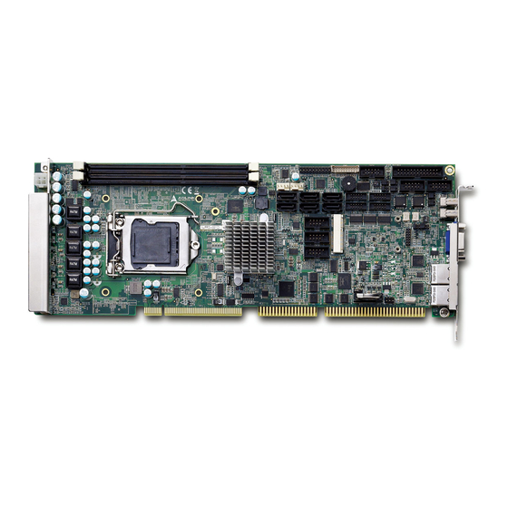
NuPRO-A331 Introduction 1.1 Overview The ADLINK NuPRO-A331 is a PICMG 1.0 Single Board Computer (SBC) supporting the next-generation Intel® Core™ i7/i5/i3 and Pentium® processors in LGA1156 package to deliver a scalable high performance platform for a wide array of industrial applications. -
Page 16: Features
1.2 Features Supports Intel® Core™ i7/i5/i3 and Pentium® processors in LGA1156 package Integrated Intel® HD Graphics on dual core 32nm (Clarkdale) processors Mini Card slot Express Dual Gigabit Ethernet 8x USB 2.0 ports (2x on bracket, 6x onboard) ... -
Page 17: Specifications
NuPRO-A331 1.3 Specifications System Intel® Core™ i7/i5/i3 and Pentium® Dual Core processors in LGA1156 package: • Intel® Core™ i7-860 Processor, 2.80 GHz, 8M Cache, 45nm, 95W, 4 cores/8 threads • Intel® Core™ i5-750 Processor, 2.66 GHz, 8M Cache, 45nm, 95W, 4 cores/4 threads •... -
Page 18: Table 1-1: Nupro-A331 General Specifications
Dimensions • 338 x 122 mm (L x W) Operating Temp. • 0ºC to 60ºC Storage Temp. • -20ºC to 80ºC Relative Humidity • 10% to 90% non-condensing Safety • CE, FCC Class A Table 1-1: NuPRO-A331 General Specifications Introduction... -
Page 19: Block Diagram
PCI to ISA DB-Audio2 Intel 82574L PCIe x1 SATA ports SATA (6x onboard) PCIe Controller Intel 82574L USB 2.0 (2x bracket, 6x onboard) PCIe Mini Card KB/Mouse BIOS ITE IT8783F Super I/O RS-232 RS-232/ 422/485/485+ Figure 1-1: NuPRO-A331 Block Diagram Introduction... -
Page 20: Functional Description
1.5 Functional Description Processor Support The NuPRO-A331 is a single processor design for the latest Intel Clarkdale (32nm) and Lynnfield (45nm) processors in LGA1156 socket (Intel® Core™ i7/i5/i3, Pentium® G6950). An integrated memory controller supports dual channel 1066/1333 MHz DDR3 and integrated Intel®... - Page 21 NuPRO-A331 Serial ATA The NuPRO-A331 provides six Serial ATA ports with data transfer rates of up to 3.0 GB/s. Intel® Rapid Storage Technology supports AHCI and RAID 0/1/5/10 functionality. Universal Serial Bus (USB) 2.0 The NuPRO-A331 provides eight USB 2.0 ports supporting trans- fer speeds up to 480 Mbps.
-
Page 22: Mechanical Drawing
1.6 Mechanical Drawing Dimensions in mm Figure 1-2: NuPRO-A331 Board Dimensions Introduction... -
Page 23: I/O Connectivity
2.54” pitch w/ bracket by cable COM3-6 — 2.00" pitch w/ bracket Parallel port — — — SATA — — — PCIe Mini Card — — — PCI 32bit/33MHz — — — — — — Table 1-2: NuPRO-A331 I/O Connectivity Introduction... -
Page 24: Power Consumption
1.8 Power Consumption Intel® Core™ i7-860 Processor, 2.80 GHz Test Configuration Intel® Core™ i7-860 Processor, 2.80 GHz ATP AQ56M64B8BJH9S 2GB DDR3 1333 Memory 2x 2GB in 2 DIMM slots Graphics Intel® Graphics Media Accelerator HD (Integrated) SATA Channel 1 Seagate ST9160412AS Barracuda 7200.4 160GB Power Supply FSP FSP350-60PFG Backplane... -
Page 25: Table 1-4: Core™ I5-660 Processor Power Consumption
NuPRO-A331 Intel® Core™ i5-660 Processor, 3.33 GHz Test Configuration Intel® Core™ i5-660 Processor, 333 GHz ATP AQ56M64B8BJH9S 2GB DDR3 1333 Memory 2x 2GB in 2 DIMM slots Graphics Intel® Graphics Media Accelerator HD (Integrated) SATA Channel 1 Seagate ST9160412AS Barracuda 7200.4 160GB... -
Page 26: Table 1-5: Core™ I3-540 Processor Power Consumption
Intel® Core™ i3-540 Processor, 3.06 GHz Test Configuration Intel® Core™ i3-540 Processor, 3.06 GHz (2 cores) Unigen MUUUDM8000ACELPAA DDR3 1333MHz Memory 2x 1GB in 2 DIMM slots Graphics Integrated on CPU SATA Channel 1 Seagate Barracuda 7200.10 160GB Power Supply LEMACS HG2-6350P 350W Backplane ADLINK EBP-5E1... -
Page 27: Table 1-6: Pentium® G6950 Processor Power Consumption
NuPRO-A331 Intel® Pentium® G6950 Processor, 2.80 GHz Test Configuration Intel® Pentium® G6950 Processor, 2.80 GHz (2 cores) Unigen MUUUDM8000ACELPAA DDR3 1333MHz Memory 2x 1GB in 2 DIMM slots Graphics Integrated on CPU SATA Channel 1 Seagate Barracuda 7200.10 160GB... -
Page 28: Package Contents
2-port COM cable w/ bracket x2 for COM3-6 (2.00mm pitch) The NuPRO-A331 must be protected from static discharge and physical shock. Never remove any of the socketed parts except at a static-free workstation. Use the anti-static bag shipped with WARNING: the product to handle the board. -
Page 29: Hardware Information
NuPRO-A331 Hardware Information This chapter provides information on the NuPRO-A331 board lay- out, connector pin assignments, and jumper settings. 2.1 Rear Panel I/O Ports Figure 2-1: Rear Panel I/O Ports Connector Description LAN1 port Gigabit Ethernet (RJ-45) LAN2 port Gigabit Ethernet (RJ-45) - Page 30 LAN (RJ-45) Ports 10BASE-T/ Pin # 1000BASE-T 100BASE-TX BI_DA+ BI_DA- LED1 LED2 BI_DB+ BI_DC+ BI_DC- BI_DB- BI_DD+ BI_DD- Refer to the table below for the LAN port LED definitions. LED1 LED2 Status Description Status Description No Link 10 Mb connection Linked Green 100 Mb connection...
- Page 31 NuPRO-A331 VGA Port Pin # Signal Green Blue Ground Ground Ground Ground +5 V Ground DDC DAT HSYNC VSYNC DDC CLK Hardware Information...
-
Page 32: Board Layout
2.2 Board Layout 10 11 12 Figure 2-2: Connectors and Jumpers Connector Description ATX 12V Power connector DIMM1/2 DDR3 DIMM slots FAN1 FAN1 connector FAN2 FAN2 connector CN27 System Panel pin header CN7/8/11/12/28/29 SATA connectors DVI-D onboard connector CN13/14/17/18 COM3/4/5/6 connector CN26 Audio connector CN10... -
Page 33: Onboard Connectors
NuPRO-A331 2.3 Onboard Connectors ATX 12V Power Connector (CN1) Pin # Signal +12V DC +12V DC The ATX 12V power connector must be connected to provide sufficient power to the SBC in either ATX or AT modes. See “Installing the Power Connectors” on page 36. - Page 34 DVI-D Bracket Connector (optional cable w/ bracket, P/N 30-01052-2000) Pin # Signal Pin # Signal TMDS Data2- TMDS Data3+ TMDS Data2+ +5 V Power TMDS Data2/4 Shield TMDS Data4- Hot Plug Detect TMDS Data4+ TMDS Data0- DDC Clock [SCL] TMDSData0+ DDC Data [SDA] TMDS Data0/5 Shield Analog vertical sync...
- Page 35 NuPRO-A331 PS/2 Keyboard/Mouse Bracket Connectors (optional cable w/ bracket, P/N: 30-01019-2000) PS/2 Mouse Port (green) Pin # Signal Function MSDATA Mouse Data not connected Ground Power Clock not connected PS/2 Keyboard Port (purple) Pin # Signal Function KBDATA Keyboard Data...
- Page 36 Parallel Port Onboard Connector (CN5) (2x13 box header, 2.54mm pitch) Pin # Signal Pin # Signal Line Printer Strobe Auto-Feed Parallel Data 0 Error Parallel Data 1 Initialize Parallel Data 2 Select Parallel Data 3 Ground Parallel Data 4 Ground Parallel Data 5 Ground Parallel Data 6...
- Page 37 NuPRO-A331 COM1/2 Connector (RS-232/422/485/485+) (CN6/10) (2x5 box header, 2.54mm pitch) Pin # RS-232 RS-422/485+ RS-485 TXD- Data- TXD+ Data+ RXD+ RXD- Note: See “COM1/2 Mode Jumper Settings” on page 28 for instructions on how to set COM1/2 to RS-232/422/485/485+ mode.
- Page 38 COM Bracket Connectors (cables w/ bracket supplied with the NuPRO-A331 - DB9 connector) Pin # RS-232 RS422/485+ RS485 TXD- Data- TXD+ Data+ RXD+ Serial ATA Connectors (CN7/8/11/12/28/29) (7P L-connector, 1.27mm pitch) Pin # Signal USB 2.0 Connectors (CN19/20/21) (2x5 box header, 2.54mm pitch)
- Page 39 NuPRO-A331 HD Audio Daughter Board Connector (CN26) (2x5 box header, 2.54mm pitch) This connector is designed for use with the ADLINK DB-Audio2 daughter board. Pin # Signal Function Ground AUD_BCLK Audio Clock Ground ICH_AUD_SDIN1 Audio Data Input + 5V ICH_AUD_SDOUT Audio Data Output...
- Page 40 System Panel Pin Header (CN27) (2x10 pin header, 2.54mm pitch) Connects to chassis-mounted buttons, speakers, and LEDs. Pin # Signal Function Pin Group +5V Power Power LED HC_PLED-L Power LED signal Ground Ground ATX Power ATX_PSON-L ATX Power-On signal P5V_SB_ATX +5V Standby PMEJ Power Control signal...
- Page 41 NuPRO-A331 PCIe Mini Card VGA Pin Header(JP6) (2x7 pin header, 2.00mm pitch) This header is connected to the optional mPCIe-8770 to provide graphics output to the VGA connector on the rear panel. Pin # Signal Pin # Signal CRTDAT CRTCLK...
-
Page 42: Jumpers
2.4 Jumpers Clear CMOS (JBAT1) The CMOS RAM data contains the date/time and BIOS setting information. CMOS is powered by the onboard button cell battery. To erase the CMOS RAM data: 1. Power down and disconnect power from the system. 2. -
Page 43: Getting Started
This chapter provides information on how to install components on the NuPRO-A331 SBC. 3.1 Installing the CPU The NuPRO-A331 supports an Intel® Core™ i7/i5/i3 or Pentium® processor in an LGA1156 socket. Disconnect all power to the board before installing a CPU to prevent damaging the board and CPU. - Page 44 2. Raise the locking arm to unlock the load plate. 3. Lift the load plate to uncover the socket. 4. Remove the plastic protective cover from the socket. Note the locations of the alignment keys (A) and Pin 1 indicator (B). DO NOT touch socket contacts.
- Page 45 NuPRO-A331 5. Hold the CPU using thumb and forefinger as shown. Position the CPU over the socket, matching the notches on the sides of the CPU with the alignment keys on the socket (A). The golden triangle on the CPU must be positioned at the corner of the socket with the Pin 1 indi- ...
- Page 46 7. Gently lower the load plate. Make sure the front edge of the plate is under the screw as indicated. 8. Lower the locking arm and fasten it to the retention tab (A). The load plate should be locked underneath the screw as shown (B).
-
Page 47: Installing The Cpu Fan And Heatsink
NuPRO-A331 3.2 Installing the CPU Fan and Heatsink The CPU requires a chassis with an airflow inlet and maximum internal ambient temperature of 60° C. An approved CPU heat- sink and fan must be installed before using the SBC. Failure to... -
Page 48: Installing Memory Modules
3.3 Installing Memory Modules The NuPRO-A331 supports up to 8 GB of DDR3 1066/1333 MHz memory modules in two DIMM sockets. A DDR3 module has a 240-pin footprint compared to the legacy 184-pin DDR DIMM. DDR3 modules are notched to facilitate correct installation in the DIMM sockets. - Page 49 NuPRO-A331 3. Align the memory module on the socket making sure that the notch matches the break on the socket. Notch Break 4. Insert the module firmly into the slot until the retaining clips snap back inwards and the module is securely seated....
-
Page 50: Installing The Power Connectors
ATX 12V Power Connector The NuPRO-A331 requires +12V DC power connected to CN1 for proper operation in either ATX or AT modes. If necessary, order a ATX12V Convert Cable from ADLINK for use with Molex 4-pin power connectors (P/N 30-00006-0000). -
Page 51: Driver Installation
NuPRO-A331 Driver Installation This chapter provides information on how to install the NuPRO-A331 device drivers under Windows XP 32-bit. The device drivers are located in the following ADLINK All-in-One DVD directories: Chipset \NuPRO\NuPRO-A331\Chipset\ Display \NuPRO\NuPRO-A331\VGA\ \Add-On Card\mPCIe-8770\ Ethernet \NuPRO\NuPRO-A331\Ethernet\ \NuPRO\NuPRO-A331\TPM\ .Net Framework \NuPRO\NuPRO-A331\Others\... -
Page 52: Intel® Q57 Express Chipset Driver
Intel® HD Graphics on dual core 32nm (Clarkdale) processors. Before installing the graphics driver, first install Microsoft .NET Framework 3.5 SP1 (not required for Windows 7). 1. Locate the directory X:\NuPRO\NuPRO-A331\Others\ on the ADLINK All-in-One DVD, and extract the contents of the follow- ing archive: Microsoft_Net_Framework_v3.5_SP1.zip 2. -
Page 53: Ethernet Driver
4.4 Ethernet Driver Follow these instructions to install the Ethernet driver. 1. Locate the directory X:\NuPRO\NuPRO-A331\Ethernet\ on the ADLINK All-in-One DVD, and extract the contents of the following archive: Network Adapter Driver_15.4.1_Windows XP_32.zip. 2. Run the program Network Adapter Driver_15.4.1_Windows XP_32.exe and follow the onscreen instructions. -
Page 54: Tpm Driver
(Advanced)’ and then click ‘Next’. 6. Locate the following folder on the ADLINK All-in-One DVD: X:\NuPRO\NuPRO-A331\ISA. Press ‘Next’ to install the ite.inf file. 7. After successfully installing the files, the ‘Hardware Update Wizard’ will display the ‘Completing the Hard- ware Update Wizard’... -
Page 55: Audio Driver
Controller. This device is the Intel Active Management Technol- ogy Management Engine. Intel Active Management Technology is not supported by the NuPRO-A331, but the driver can be installed in order to remove the “question mark” from the Device Manager. Follow these instructions to install the Intel® Active Management Technology driver. - Page 56 This page intentionally left blank. Driver Installation...
-
Page 57: Bios Setup
NuPRO-A331 BIOS Setup The following chapter describes basic navigation for the AMIBIOS®8 BIOS setup utility. 5.1 Starting the BIOS To enter the setup screen, follow these steps: 1. Power on the motherboard 2. Press the < Delete > key on your keyboard when you see the following text prompt:... - Page 58 Setup Menu The main BIOS setup menu is the first screen that you can navi- gate. Each main BIOS setup menu option is described in this user’s guide. The Main BIOS setup menu screen has two main frames. The left frame displays all the options that can be configured.
- Page 59 NuPRO-A331 Note: There is a hot key legend located in the right frame on most setup screens. The < F8 > key on your keyboard is the Fail-Safe key. It is not dis- played on the key legend by default. To set the Fail-Safe settings of the BIOS, press the <...
- Page 60 The < F10 > key allows you to save any changes you have made and exit Setup. Press the < F10 > key to save your changes. The following screen will appear: Press the < Enter > key to save the configuration and exit. You can also use the <...
-
Page 61: Main Setup
NuPRO-A331 5.2 Main Setup When you first enter the Setup Utility, you will enter the Main setup screen. You can always return to the Main setup screen by select- ing the Main tab. There are two Main Setup options. They are described in this section. -
Page 62: Advanced Bios Setup
5.3 Advanced BIOS Setup Select the Advanced tab from the setup screen to enter the Advanced BIOS Setup screen. You can select any of the items in the left frame of the screen, such as SuperIO Configuration, to go to the submenu for that item. You can display an Advanced BIOS Setup option by highlighting it using the <... -
Page 63: Cpu Configuration
NuPRO-A331 5.3.1 CPU Configuration Intel® Virtualization Tech When enabled, Intel® Virtualization Technology (Intel® VT) makes a single system appear as multiple independent sys- tems to software. This allows for multiple, independent operat- ing systems to be running simultaneously on a single system. -
Page 64: Ide Configuration
5.3.2 IDE Configuration Configure SATA as Options: IDE, RAID, AHCI, Disabled SATA#1 IDE Configuration When running in Compatible mode, SATA channels 1, 2, 3 and 4 can be configured as legacy IDE channels. SATA#2 IDE Configuration When running at compatible mode, SATA channels 5 and 6 can be configured as legacy IDE channels. -
Page 65: Super Io Configuration
NuPRO-A331 5.3.3 Super IO Configuration Serial Port1-6 Address/IRQ Specifies the serial port addresses. The options are: Port1-2: 3F8, 2F8, 3E8, 2E8, Disabled Port3-6: 3F8, 2F8, 3E8, 2E8, 2F0, 2E0, Disabled IRQ settings are fixed as shown. Parallel Port Address/IRQ This option specifies the base I/O port address and IRQ of the parallel port. -
Page 66: Hardware Health Configuration
5.3.4 Hardware Health Configuration This option displays the current status of all of the monitored hard- ware devices/components such as voltages and temperatures. The options are Enabled and Disabled. H/W Health Function Select this option to enable or disable the BIOS Hardware Health Monitoring Device. - Page 67 NuPRO-A331 Automatic Mode Temperature 1 Limit of OFF When the temperature (°C) is higher than the set value, Fan1/2 will run at Start PWM speed. When the temperature is lower than the set value, Fan1/2 will stop. Temperature 1 Limit of Start When the temperature (°C) is higher than the set value, Fan1/2...
- Page 68 PWM Manually Mode Fan 1/2 PWM Control Sets a value to control the fan speed. Minimum is 0 and Maxi- mum is 127. BIOS Setup...
-
Page 69: Acpi Settings
NuPRO-A331 5.3.5 ACPI Settings ACPI OS Shutdown Mode This option sets the OS shutdown mode to ATX or AT. ATX: OS will turn off system power when shutdown. AT: OS will display “It is now safe to turn off your computer."... -
Page 70: Ahci Configuration
5.3.6 AHCI Configuration You can use this screen to select options for the AHCI Settings. Use the up and down < Arrow > keys to select an item. Use the < + > and < - > keys to change the value of the selected option. BIOS Setup... -
Page 71: Remote Access Configuration
NuPRO-A331 5.3.7 Remote Access Configuration Remote access configuration provides the settings to allow remote access by another computer to get POST messages and send commands through serial port access. Remote Access Select this option to enable or disable the BIOS remote access feature. - Page 72 Serial Port Mode Select the baud rate you want the serial port to use for console redirection. The options are 115200 8,n,1; 57600 8,n,1; 19200 8,n,1; and 09600 8,n,1. Flow Control Set this option to select Flow Control for console redirection. The settings for this value are None, Hardware, or Software.
-
Page 73: Trusted Computing
NuPRO-A331 5.3.8 Trusted Computing Trusted computing is an industry standard to make personal com- puters more secure through a dedicated hardware chip, called a Trusted Platform Module (TPM). This submenu provides allows you to enable/disable, execute and clear the TPM. -
Page 74: Usb Configuration
5.3.9 USB Configuration Legacy USB Support Legacy USB Support refers to USB mouse and keyboard sup- port. Normally if this option is not enabled, any attached USB mouse or USB keyboard will not become available until a USB compatible operating system is fully booted with all USB driv- ers loaded. - Page 75 NuPRO-A331 USB 2.0 Controller Mode The USB 2.0 Controller Mode configures the data rate of the USB port. The options are FullSpeed (12 Mbps) and HiSpeed (480 Mbps). Legacy USB 1.1 HC Support Enables/disables legacy USB 1.1 host controller support.
-
Page 76: Pci/Pnp Settings
5.4 PCI/PnP Settings Select the PCI/PnP tab from the setup screen to enter the Plug and Play BIOS Setup screen. You can display a Plug and Play BIOS Setup option by highlighting it using the < Arrow > keys. The Plug and Play BIOS Setup screen is shown below. -
Page 77: Boot Settings
NuPRO-A331 5.5 Boot Settings Select the Boot tab from the setup screen to enter the Boot BIOS Setup screen. You can select any of the items in the left frame of the screen, such as Boot Device Priority, to go to the submenu for that item. - Page 78 Quick Boot Enabling this setting will cause the BIOS power-on self test routine to skip some of its tests during bootup for faster system boot. Quiet Boot When this feature is enabled, the BIOS will display the full- screen logo during the boot-up sequence, hiding normal POST messages.
-
Page 79: Boot Device Priority
NuPRO-A331 5.5.2 Boot Device Priority The items allow you to set the sequence of boot devices where BIOS attempts to load the disk operating system. First press <Enter> to enter the sub-menu. Then you may use the arrow keys to select the desired device, then press <+>, <-> or <PageUp>, <PageDown>... -
Page 80: Security Setup
5.6 Security Setup Password Support Two Levels of Password Protection Provides both a Supervisor and a User password. If you use both passwords, the Supervisor password must be set first. The system can be configured so that all users must enter a password every time the system boots or when Setup is exe- cuted, using either or either the Supervisor password or User password. - Page 81 NuPRO-A331 Remember the Password Keep a record of the new password when the password is changed. If you forget the password, you must erase the sys- tem configuration information in NVRAM. To access the submenu for the following items, select the item and press <...
-
Page 82: Chipset Setup
5.7 Chipset Setup Select the Chipset tab from the setup screen to enter the Chipset BIOS Setup screen. You can select any of the items in the left frame of the screen to go to the submenu for that item. The Chip- set BIOS Setup screen is shown below. -
Page 83: Graphics And Memory Configuration
NuPRO-A331 5.7.1 Graphics and Memory Configuration Initial Graphics Adapter Select which graphics controller to use as the primary boot device. (“PCI” includes PCI slot and and PCIe Mini Card. PCI will be first.) IGD: Integrated graphics only. PCI/IGD: Detect PCI graphics first, then integrated graphics... -
Page 84: Pch Configuration
5.7.2 PCH Configuration HDA Controller Set this value to Enable/Disable the HD Audio Controller. 82574L LAN Boot Set this value to enable/disable the LAN controller. Restore on AC Power Loss Determines which state the computer enters when AC power is restored after a power loss. -
Page 85: Exit Menu
NuPRO-A331 5.8 Exit Menu Select the Exit tab from the setup screen to enter the Exit BIOS Setup screen. You can display an Exit BIOS Setup option by high- lighting it using the < Arrow > keys. The Exit BIOS Setup screen is shown below. - Page 86 Discard Changes and Exit Setup Now? [Ok] [Cancel] appears in the window. Select Ok to discard changes and exit. Discard Changes Select Discard Changes from the Exit menu and press < Enter >. Select Ok to discard changes. Load Optimal Defaults Automatically sets all Setup options to a complete set of default settings when you select this option.
-
Page 87: A Appendix: Watchdog Timer
NuPRO-A331 Appendix A - Watchdog Timer A sample program for configuring the NuPRO-A331’s watchdog timer is included on the ADLINK All-in-One DVD in the following directory: \NuPRO\NuPRO-A331\WDT. A.1 Sample Code #include<stdio.h> #include<dos.h> static unsigned int IT8783_ioPort = 0x2e; void Enter_IT8783_Config(unsigned int flag) if(flag) IT8783_ioPort = 0x4e;... - Page 88 Get_IT8783_ID(unsigned int &ID1, unsigned int &ID2) outportb(IT8783_ioPort, 0x20); ID1 = inportb(IT8783_ioPort+1); outportb(IT8783_ioPort, 0x21); ID2 = inportb(IT8783_ioPort+1); void IT8783_WDTRun(unsigned int count_value, unsigned int PLEDflag) //for NuPRO-A331 unsigned long tempCount; unsigned int registerValue; outportb(IT8783_ioPort, 0x07); outportb(IT8783_ioPort+1, 0x07);// Device 7 outportb(IT8783_ioPort, 0xf8); outportb(IT8783_ioPort+1, 0x00);// PLED mapping to...
- Page 89 NuPRO-A331 outportb(IT8783_ioPort, 0xf8); outportb(IT8783_ioPort+1, 0x1f);// PLED mapping to GP37 outportb(IT8783_ioPort, 0xf9); registerValue = inportb(IT8783_ioPort + 1); registerValue |= 0x02; registerValue &= 0xfb; outportb(IT8783_ioPort+1, registerValue); outportb(IT8783_ioPort, 0x71); registerValue = inportb(IT8783_ioPort + 1); registerValue &= 0xfe; outportb(IT8783_ioPort+1, registerValue); outportb(IT8783_ioPort, 0x72); registerValue = inportb(IT8783_ioPort + 1);...
- Page 90 registerValue = inportb(IT8783_ioPort+1); registerValue |= 0x80; tempCount = count_value; if(tempCount != 0) printf("WDT timeout in %d seconds.\n", tempCount); registerValue |= 0x40; //Enable WDT output through KBRST else printf("WDT is Disabled.\n"); registerValue &= 0xbf; //Disable WDT output through KBRST outportb(IT8783_ioPort+1, registerValue); // set WDT count is second outportb(IT8783_ioPort, 0x71);...
-
Page 91: B Appendix: System Resources
NuPRO-A331 Appendix B - System Resources B.1 System Memory Map Address Range Address Range Size Description (decimal) (hex) FFE00000 – (4GB-2MB) 2 MB High BIOS Area FFFFFFFF (4GB-18MB) – FEE00000 – 1 MB FSB Interrupt Memory Space (4GB-17MB-1) FEEFFFFF (4GB-20MB) –... -
Page 92: Io Map
B.3 IO Map Hex Range Device 000-01F DMA controller 1, 8237A-5 equivalent 020-02D and 030-03F Interrupt controller 1, 8259 equivalent 02E-02F, 04E-04F LPC SIO (ITE8783) configuration index/data registers 040-042, 050-052 Timer, 8254-2 equivalent 060, 062, 064, 066 8742 equivalent (keyboard) NMI control and status 070-077 Real Time Clock Controller( bit 7 -NMI mask) -
Page 93: Interrupt Request (Irq) Lines
NuPRO-A331 B.4 Interrupt Request (IRQ) Lines IRQ Lines PIC Mode Typical Interrupt IRQ# Connected to Pin Available Resource Counter 0 Keyboard controller Cascade interrupt from slave PIC IRQ3 via SERIRQ, Serial Port 5 (COM5) Note (1) IRQ3 at ISA bus IRQ4 via SERIRQ, ... - Page 94 IRQ Lines APIC Mode Typical Interrupt IRQ# Connected to Pin Available Resource Counter 0 Keyboard controller Cascade interrupt from slave PIC IRQ3 via SERIRQ, IRQ3 at ISA Serial Port 5 (COM5) Note (1) Serial Port 1-4 IRQ4 via SERIRQ, IRQ4 at ISA Note (1) (COM1.2.3.4) IRQ5 via SERIRQ, IRQ5 at ISA...
-
Page 95: Table B-5: Irq Lines Apic Mode
NuPRO-A331 Typical Interrupt IRQ# Connected to Pin Available Resource PCIE Port #2, UHCI Controller #3, UHCI Controller #6, Thermal Controller, SMBus Controller, SATA Host Controller, IDER Controller PCIE Port #3, UHCI Controller #1, UHCI ontroller #7, SATA Host Controller1 PCI Slot 4 , GbE Controller... - Page 96 PCI Configuration Space Map Bus # Device # Function # Routing Description Intel PCH 5 Series Bridge Internal PEG #1 Root Port 0FFh PEG #1 Portt Internal PEG #2 Root Port 0FFh PEG #2 Portt Internal PEG #3 Root Port 0FFh PEG #3 Portt Internal...
-
Page 97: Table B-6: Pci Configuration Space Map
NuPRO-A331 Bus # Device # Function # Routing Description Internal Intel USB EHCI Controller #1 Intel PCI to PCI Bridge Intel LPC Interface Bridge Internal Intel SATA controller #1 Internal Intel SMBus Controller Internal Intel SATA controller #2 Internal Thermal Controller... -
Page 98: Table B-7: Pci Interrupt Routing Map
PCI Interrupt Routing Map PIRQ INT Line INTA INTB INTC INTD PEG Root Port 1-6 INTA INTB INTC INTD SATA Controller SATA Controller1 SMBUS controller Thermal Controller EHCI 1 EHCI 2 Intel GbE HECI Host 1 HECI Host 2 IDER Controller KT Controller NAND Controller PCIE Port 0... -
Page 99: Important Safety Instructions
NuPRO-A331 Important Safety Instructions For user safety, please read and follow all instructions, WARNINGS, CAUTIONS, and NOTES marked in this manual and on the associated equipment before handling/operating the equipment. Read these safety instructions carefully. Keep this user’s manual for future reference. - Page 100 Never attempt to fix the equipment. Equipment should only be serviced by qualified personnel. A Lithium-type battery may be provided for uninterrupted, backup or emergency power. Risk of explosion if battery is replaced with one of an incorrect type. Dispose of used batteries appropriately. WARNING: ...
-
Page 101: Getting Service
Address: 5215 Hellyer Avenue, #110, San Jose, CA 95138, USA Tel: +1-408-360-0200 Toll Free: +1-800-966-5200 (USA only) Fax: +1-408-360-0222 Email: info@adlinktech.com ADLINK Technology (China) Co., Ltd. Address: (201203) 300 Fang Chun Rd., Zhangjiang Hi-Tech Park, Pudong New Area, Shanghai, 201203 China Tel: +86-21-5132-8988 Fax:... - Page 102 Address: 84 Genting Lane #07-02A, Cityneon Design Centre, Singapore 349584 Tel: +65-6844-2261 Fax: +65-6844-2263 Email: singapore@adlinktech.com ADLINK Technology Singapore Pte. Ltd. (Indian Liaison Office) Address: No. 1357, "Anupama", Sri Aurobindo Marg, 9th Cross, JP Nagar Phase I, Bangalore - 560078, India Tel: +91-80-65605817 Fax: +91-80-22443548 Email: india@adlinktech.com...
Need help?
Do you have a question about the NuPRO-A331 and is the answer not in the manual?
Questions and answers